
Manuales relacionados para BH HI POWER L080


Resumen de contenidos para BH HI POWER L080
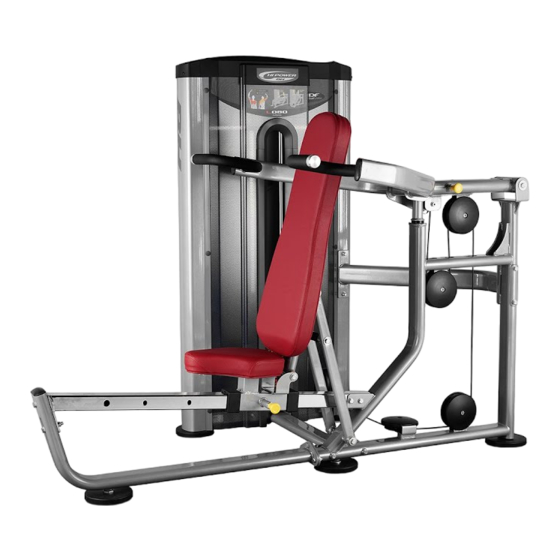
- Página 1 L080 Instrucciones de montaje y utilización Instructions for assembly and use Instructions de montage et d’utilisation Hinweise zur Montage und Benutzung...
- Página 2 L080 INSTRUCCIONES DE SEGURIDAD.- Rogamos leer estas instrucciones atentamente, antes del montaje y del primer uso. Obtendrá importantes informaciones para su seguridad, así como para el uso y para el mantenimiento del aparato de ejercicio. Guardar cuidadosamente las instrucciones para su información, así como para los trabajos de mantenimiento o los pedidos de piezas de repuesto.
- Página 3 SAFETY INSTRUCTIONS Please read these instructions carefully before assembling and using the equipment. They contain important information for your safety and for the use and maintenance of the exercise equipment. Keep the instructions safe for future reference and maintenance tasks as well as for ordering spare parts.
- Página 4 INSTRUCTIONS DE SÉCURITÉ - Nous recommandons de lire attentivement ces instructions avant de procéder au montage et d’utiliser l'appareil pour la première fois. Ce manuel contient des informations importantes relatives à la sécurité, à l’usage et à l’entretien de la machine d’exercice. Conserver soigneusement ces instructions à...
- Página 5 SICHERHEITSHINWEISE.- Bitte lesen Sie diese Hinweise vor der Montage und ersten Benutzung des Geräts aufmerksam. Hier finden Sie wichtige Informationen zu Ihrer Sicherheit, zur Benutzung und zur Wartung Ihres Trainingsgeräts. Bewahren Sie diese Hinweise sorgfältig auf, um sie jederzeit zum Nachschlagen oder für erforderliche Informationen zur Wartung oder Bestellung von Ersatzteilen zur Hand zu haben.
- Página 6 Saque la unidad de la caja, compruebe e identifique las piezas con respecto al listado de la Fig.A y Fig.B, para asegurarse de que no falta ninguna pieza, para el montaje del equipo, en la primera fase. Take the unit out of its box, check and identify the parts against the list in Fig. A and Fig. B to ensure that there are no missing parts for the initial assembly stage of the equipment.
- Página 9 Fig.B Nº Nº M-10*110 M-12*140 M-10*100 M-10*115 M-10*65 M-10*75 M-10*40 M-10*60 M-10*30 M-10*25 M-10*20 M-10*150 M-12 M-10 M-10(φ38*11*2) M-10 M-12 M-10(φ30*11*2) M-5*12...
- Página 10 INSTRUCCIONES DE MONTAJE.- NOTA: La descripción de las piezas con respecto a las figuras, corresponden siempre a la posición de la persona en el equipo para la realización del ejercicio. INSTRUCTIONS FOR ASSEMBLY.- NOTE: The description of the parts with respect to the figures always corresponds to the position the person adopts on the equipment when exercising.
- Página 11 Fig.2 Coloque el soporte (2) en el soporte (11), atorníllelo con los tornillos (54) junto con las arandelas (63) y las tuercas (60). Enrosque los tacos de nivelación (27) en el soporte (11). A continuación coloque el soporte (11) y atorníllelo a los soportes (9) y (10), únalos con los tornillos (45) (46) junto con las arandelas (63) y las tuercas (60).
- Página 12 Fig.3 Coloque el soporte (3) en el soporte (2), atorníllelo con los tornillos (48), (49) y (50) junto con las arandelas (63) y las tuercas (60). Posicione el brazo (7) en el eje del soporte (3). Introduzca el eje (14) coloque las arandelas (35) y apriete con el tornillo (104) junto con las arandelas (64) y las tuercas (61).
- Página 13 Fig.4 Posicione el brazo izquierdo (8) en el eje del soporte (7) y (11). Introduzca los casquillos (22) coloque las arandelas de aluminio (65) y apriete con los tornillos (55). Introduzca el eje (17) y (34) coloque las arandelas (65) y apriete con el tornillo (53). Repita el proceso con el brazo derecho (8).
- Página 14 Fig.5 Posicione el brazo (6) en el eje del soporte (11). Introduzca el eje (18) coloque las arandelas de aluminio (62) y apriete con los tornillos (55). Posicione el brazo (5) en el eje del soporte (6). Introduzca el eje (15) coloque las arandelas de aluminio (62) y apriete con los tornillos (55). Introduzca el tornillo (56).
- Página 15 Fig.6 Posicione la chapa (60) de sujeción carcasa delantera y apriete con el tornillo (86) junto con la arandela plana (88). Sitúe el tope de pesas (26) en la torre de pesas (1), introduzca las barras de pesas (16). A continuación coloque las pesas (94); (95), (96), siempre las de mayor peso en la parte inferior, por ultimo coloque la pesa de guía con su barra selectora (21), atornille las barras de pesas por la parte superior con las arandelas (63) y los tornillos (55).
- Página 16 Fig.7 Atornille la punta del cable (42) en la pesa de guía (21), coja la otra punta del cable (42) y páselo por las poleas superiores y las poleas inferiores, atornille la otra punta del cable en el soporte (74) con el tornillo (91) junto con las arandelas (63) y la tuerca (90).
- Página 17 Fig.8 Introduzca la carcasa delantera (28), desde la parte superior en dirección de la flecha en la torre de pesas (1). Coloque los insertos (85) a los dos lados de la torre. Fit the front casing (28) onto the weight stack (1), from the top in the direction of the arrow. Fit the inserts (85) to the two sides of the weight stack.
- Página 18 Fig.9 Introduzca la carcasa trasera (29), desde la parte superior en dirección de la flecha en la torre de pesas (1). Fit the rear casing (29) onto the weight stack (1), from the top in the direction of the arrow. Insérer la partie postérieure (29), par le haut en direction de la flèche dans la tour de poids (1).
- Página 19 Fig.10 Introduzca la carcasa superior (12), desde la parte superior en dirección de la flecha en la torre de pesas (1). Coloque las arandelas (88) y los tornillos (86). Fit the top casing (12) onto the weight stack (1), from the top in the direction of the arrow. Fit the washers (88) and screws (86).
- Página 20 Fig.11 Posicione el respaldo (38) sobre el apoyo (7), atorníllelo con los tornillos (54) junto con las arandelas (63). A continuación posicione el asiento (37) en el soporte (4), atorníllelo con los tornillos (54) junto con las arandelas planas (63). Position the backrest (38) on the support (7), secure it using screws (54) along with the washers (63).
- Página 21 MUY IMPORTANTE: Una vez realizado el montaje, compruebe que todos los tornillos que han sido montados en esta maquina, están fuertemente apretados. VERY IMPORTANT: After assembling the unit, check that all of the screws have been fitted to the machine and that they are tightened securely.
- Página 22 L080...
- Página 23 Para pedido de repuesto: Indicar el código de la pieza y la cantidad To order replacement parts: State the part code and Quantity Pour commander des pièces de rechange: Indiquer le code de la pièce de rechange et la quantité désirée.
- Página 24 BH HIPOWER SPAIN BH HIPOWER PORTUGAL BH HIPOWER UK MAQUINASPORT, S.A. EXERCYCLE,S.L. (Manufacturer) Unit 12 Arlington Court Zona Industrial Giesteira P.O.BOX 195 Newcastle Staffs Terreirinho 3750-325 Agueda 01080 VITORIA (SPAIN) ST5 6SS (PORTUGAL) Tel.: +34 945 29 02 58 UK 0844 3353988 Tel.: +351 234 729 510 Fax: +34 945 29 00 49 International 00441782634703...