Publicidad
Enlaces rápidos
IMPORTANT SAFETY
INSTRUCTIONS
READ ALL SAFETY WARNINGS,
WARNING
I N S T R U C T I O N S, I L L U S T R A-
TIONS AND SPECIFICATIONS PROVIDED
WITH THIS TOOL. Failure to follow all instructions
listed below may result in electric shock, fire and/or
serious injury. SAVE THESE INSTRUCTIONS -
THIS OPERATOR'S MANUAL CONTAINS IM-
PORTANT SAFETY AND OPERATING IN-
STRUCTIONS.
• Make sure that all pieces of this device and the tool
are securely mounted before operation.
•Always use common sense and be cautious when
using tools. It is not possible to anticipate every
situation that could result in a dangerous outcome.
Do not use this tool if you do not understand these
operating instructions or you feel the work is beyond
your capability; contact Milwaukee Tool or a trained
professional for additional information or training.
• Maintain labels and nameplates. These carry
important information. If unreadable or missing,
contact a MILWAUKEE service facility for a free
replacement.
FUNCTIONAL DESCRIPTION
2
3
11
10
9
1. Non-marring
7. Metal mounting plate
ceiling pad
8. Quick adjustment
2. Spring rod
knob
3. Swivel back plate
9. Extension
4. Clamp body
10. Screw-on floor pad
5. Jaw grip
11. Reference marks
6. Lead screw
SYMBOLOGY
Read operator's manual
SPECIFICATIONS
Cat. No. ................................................48-35-1511
Usable Range ................................................. 0-12'
Macro Adjustment ...........................................5'-12'
Laser Compatibility ................. MILWAUKEE lasers
ASSEMBLY
Only use accessories specifically
WARNING
recommended for this tool. Others
may be hazardous.
Assembling Laser Mounting Pole
Make sure that all pieces of this device and the tool
are securely mounted before operation.
1. Review height needed. Assemble pole sections
to desired height.
2. Attach screw-on bottom floor pad.
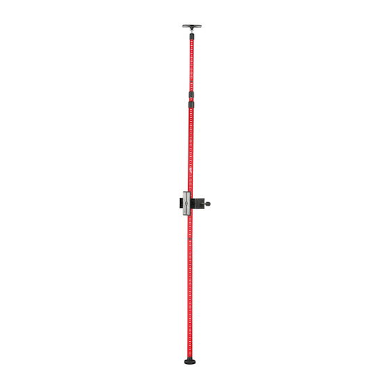
12' TELESCOPING LASER POLE
PERCHE TÉLESCOPIQUE DE MONTAGE POUR
Cat. No. / No de cat.
LASER DE 365,8 cm (12')
48-35-1511
MÁSTIL TELESCÓPICO PARA LÁSER DE 365,8 cm (12')
3. Attach swivel head by firmly pushing cup section
into ball section until pieces snap into place.
4. Loosen clamp using quick adjustment knob.
5. Place clamp onto pole and use quick adjustment
knob to tighten clamp into place.
OPERATION
Quick Release Feature
1. Twist the quick adjustment knob counterclockwise
to disengage threads.
2. Slide jaw to desired position by pushing and pull-
ing lead screw.
3. Twist the quick adjustment knob clockwise to
reengage threads and tighten the clamp.
Adjusting Clamp
1. To mount the clamp to the pole,
turn the lead screw knob on the
bottom counterclockwise to loos-
en. Put the pole in between the jaw
pieces and slide together. Turn
knob clockwise to tighten.
2. To loosen, rotate the knob coun-
terclockwise and slide jaw apart.
3. To rotate the swivel plate, firmly
grasp the back plate of clamp and
clamp body and twist in opposite
directions. The clamp itself will al-
low for 360 degrees of rotation in
90 degree intervals.
4
Adjusting Pole
1. Before use, add or remove bottom pole section
depending on needed height.
5
2. To slide pole up or down, twist the pole sections to
tighten (clockwise) or loosen (counterclockwise).
3. Extend pole to ceiling height, and apply pressure to
6
ceiling and ceiling pad on tool to compress spring
then twist clockwise to lock in place.
REFERENCE IMAGES
IMÁGENES DE REFERENCIA
7
IMAGES DE RÉFÉRENCE
8
DIRECTIVES DE SÉCURITÉ
IMPORTANTES
LIRE TOUS LES AVER-
AVERTISSEMENT
TISSEMENTS DE SÉ-
CURITÉ ET INSTRUCTIONS EN VOUS
RÉFÉRANT AUX ILLUSTRATIONS DES
BULLETINS FOURNIS AVEC LE PRÉSENT
ÉQUIPEMENT. Ne pas suivre toutes les in-
structions énumérées ci-dessous, pourrait
causer un choc électrique, un incendie et/ou
des blessures graves. SAUVEGARDEZ CES
INSTRUCTIONS - LE PRÉSENT MANUEL
DU PROPRIÉTAIRE CONTIENT DES IN-
STRUCTIONS DE FONCTIONNEMENT ET
DE SÉCURITÉ IMPORTANTES.
• Assurez-vous que toutes les pièces de cet ap-
pareil et de l'outil sont solidement fixées avant
l'utilisation.
• Toujours faire preuve de bons sens et procéder
avec prudence lors de l'utilisation d'outils. C'est
impossible de prévoir toutes les situations dont le
résultat est dangereux. Ne pas utiliser cet outil si
vous ne comprenez pas ces instructions d'opération
ou si vous pensez que le travail dépasse votre
capacité ; veuillez contacter Milwaukee Tool ou un
professionnel formé pour recevoir plus d'information
ou formation.
• Maintenir en l'état les étiquettes et les plaques
d'identification.Des informations importantes y
figurent. Si elles sont illisibles ou manquantes,
contacter un centre de services et d'entretien
MILWAUKEE pour un remplacement gratuit.
DESCRIPTION FONCTIONNELLE
2
3
11
10
9
1. Coussinet non
7. Plaque de montage
égratignant pour
en métal
plafond
8. Bouton de réglage
2. Tige à ressort
rapide
3. Plaque arrière
9. Rallonge
pivotante
10. Coussinet dévissable
4. Corps de bride
pour plancher
5. Prise de mâchoire
11. Marques
référentielles
6. Vis guide
PICTOGRAPHIE
Lire le manuel d'utilisation
SPECIFICATIONS
No de Cat. ............................................48-35-1511
Plage Utilisable ............................. 365,8 cm (0-12')
Ajustement Macro.............. 152,4-365,8 cm (5'-12')
Compatibilité Laser ................. lasers MILWAUKEE
4
5
6
7
8
Publicidad

Resumen de contenidos para Milwaukee 48-35-1511
- Página 1 Milwaukee Tool or a trained • Toujours faire preuve de bons sens et procéder en. Put the pole in between the jaw avec prudence lors de l’utilisation d’outils. C’est professional for additional information or training.
- Página 2 1. Verifique la altura requerida. Ensamble las sec- capacidades, comuníquese con Milwaukee Tool o con Caractéristique de libération rapide ciones del poste a la altura deseada.


