Tabla de contenido
Publicidad
Idiomas disponibles
Idiomas disponibles
Enlaces rápidos
No: 23775 – 11/19 rev. 3
Catalog Numbers • Les Numéros de Catalogue • Los Números de Catálogo:
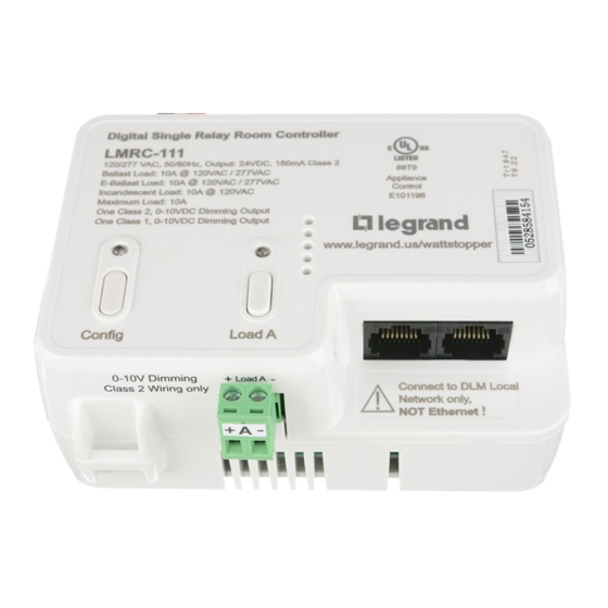
LMRC-111, LMRC-111-M, LMRC-112, LMRC-112-M
Country of Origin: Made in China • Pays d'origine: Fabriqué en Chine • País de origen: Hecho en China
Models ending in -U are BAA and TAA compliant (Product produced in the U.S.)
LMRC-111 / LMRC-111-M
This unit is pre-set for Plug n' Go™ operation, adjustment is
optional.
For full operational details, adjustment and more features of the product, see
the DLM System Installation Guide provided with the LMRC-102/11x/2xx room
controllers, and also available at www.legrand.us/wattstopper.
Installation shall be in accordance with all applicable regulations, local
and NEC codes. Wire connections shall be rated suitable for the wire size
(lead and building wiring) employed.
For Class 2 DLM devices and device wiring: To be connected to a Class 2
power source only. Do not reclassify and install as Class 1, or Power and
Lighting Wiring.
IMPORTANT SAFEGUARDS
When using electrical equipment, basic safety precautions should
always be followed including the following:
a. READ AND FOLLOW ALL SAFETY INSTRUCTIONS.
b. Do not use outdoors.
c. Do not mount near gas or electric heaters.
d. Equipment should be mounted in locations and at heights
where it will not readily be subjected to tampering by
unauthorized personnel.
e. The use of accessory equipment not recommended by the
manufacturer may cause an unsafe condition.
f. Do not use this equipment for other than intended use.
g. Installation should be performed by qualified service
personnel.
SAVE THESE INSTRUCTIONS
CAUTION: TO CONNECT A COMPUTER
TO THE DLM LOCAL NETWORK USE THE
LMCI-100. NEVER CONNECT THE DLM
LOCAL NETWORK TO AN ETHERNET
PORT – IT MAY DAMAGE COMPUTERS
AND OTHER CONNECTED EQUIPMENT.
Wattstopper
DLM Single/Dual Relay w/0-10V Dimming Room Controller
DLM relais simple/double avec contrôleur de pièce de gradation 0-10 V
Relé simple/doble DLM con controlador de regulación de habitación de 0 a 10 V
Quick Start Guide • Guide de démarrage rapide • Guía de inicio rápido
LMRC-112 / LMRC-112-M
®
SPECIFICATIONS
Input Voltage ............................................120/277VAC, 50/60Hz
Load Requirements ................................ Not to exceed 10A total
Connection to the DLM Local Network ...................2 RJ-45 ports
Each relay rated for up to:
Incandescent .............................................. 10A @ 120VAC
Ballast ................................................. 10A @ 120/277VAC
E-ballast .............................................. 10A @ 120/277VAC
Output to DLM Local Network ................ up to 150mA @ 24VDC
Class 1 & 2 Dimming Output, 0-10V sinks up to 50mA per channel
DLM Local Network Characteristics when using LMRC-111/112:
Provides low voltage power over Cat 5e cable (LMRJ);
max current 800mA. Supports up to 64 load addresses,
48 communicating devices including up to 4 LMRC-10x series
and/or LMPL-101 controllers. Free topology up to 1,000' max.
Metering capability in LMRC-111-M and LMRC-112-M provides
power monitoring within 2% of the true value.
Power monitoring capability when used with LMSM Segment
Manager.
Environment:
Operating Temperature ................32° to 131°F (0° to 55°C)
Storage Temperature ................. 23° to 176°F (-5° to 80°C)
Relative Humidity ..................... 5 to 95% (non condensing)
UL 2043 Plenum Rated, ROHS Compliant
UL/CUL listed under UL60730. These models are all
Complementary Listed to "Emergency Lighting Equipment",
(UL924) intended for Indoor Dry Locations.
MOUNTING, WIRING, AND CONNECTING
TO A DLM NETWORK
The LMRC-111/112 room controller can be mounted external to any
junction box with 1/2" knockouts, placing it in the plenum space.
All line voltage wiring is #16 AWG. Each relay is rated for up to
10A; total load for LMRC-112 not to exceed 10A. Specified load
types can connect to any load relay. Do not connect different load
types to the same relay.
For dimming ballasts, either or both the Class 1 and Class 2 0-10V
wires may be connected. For Class 1 Dimming, wiring is 18#
AWG. Connect the 0-10V control wires to the 0-10V terminals that
match the load relay output connection.
Class 1 is preferred in new installations when the violet and grey
dimming signal wires are included in the fixture power cable. Class
2 is used for new or existing installation when it is easier to run the
violet and grey dimming signal wires outside the fixture cable.
Class 1 and Class 2 wiring should be maintained thoughout the
installation and cannot be swapped - appropriate wiring practices
should be used. Class 1 and Class 2 circuitry in the LMRC units
are galvanically isolated.
The LMRC-111/112 communicates to all other DLM devices
connected to the DLM Local Network. Connections shown are for
example only. The low voltage LMRJ cables can connect to any
DLM device with an open RJ45 receptacle.
Publicidad
Tabla de contenido

Manuales relacionados para LEGRAND Wattstopper LMRC-111


Resumen de contenidos para LEGRAND Wattstopper LMRC-111
- Página 1 Metering capability in LMRC-111-M and LMRC-112-M provides the DLM System Installation Guide provided with the LMRC-102/11x/2xx room power monitoring within 2% of the true value. controllers, and also available at www.legrand.us/wattstopper. Power monitoring capability when used with LMSM Segment Manager.
- Página 2 LMRC-112 with Class 1 Dimming LMRC-112 with Class 2 Dimming O-10V Violet and Gray wires for Load A O-10V Gray and Violet wires for Load A Line Line Corner Mount Ceiling Mount DLM Local Network (Not Used for a Switched Load) (Not Used for a Switched Load) Voltage Voltage...
- Página 3 USING THE LMRC-111/112 WITH EMERGENCY LIGHTING Example using LMRC-111 When used with an ELCU Violet Wattstopper recommends using an ELCU device. In this Emergency scenario, the LMRC-111/112’s 0-10VDC dimming circuit Emergency Power Out (Red) Lighting Gray is connected to and alters the light level of both normally Emergency Neutral Gray) powered lighting loads and emergency powered lighting Emergency Power In (Black)
- Página 4 Step 2 Load selection Press and release the Config button to step through the loads connected to the DLM Local Network. As each load turns ON note the devices (switch buttons and sensors) that are showing a bright solid blue LED. These devices are currently bound to the load that is ON. The blue LED on the room controller or plug load controller connected to the load is also lit.
-
Página 5: Sauvegardes Importantes
Chaque relais a une capacité de: d'installation du système DLM fourni avec le contrôleurs de Incandescence ..............10 A à 120 VCA pièce LMRC-102/11x/2xx et aussi disponible au www.legrand.us/ Ballast ..............10 A à 120/277 VCA wattstopper. E-Ballast ..............10 A à 120/277 VCA Sortie de puissance au réseau local DLM ..... - Página 6 Le câblage de classe 1 ou classe 2 doit être maintenu tout le long de l'installation, il n'est pas possible de changer; il est nécessaire de respecter les pratiques de câblage appropriées. Les circuits de classe 1 et classe 2 dans les unités LMRC présentent une isolation galvanique.
- Página 7 UTILISATION DU LMRC-111/112 AVEC UN ÉCLAIRAGE D’URGENCE Lorsqu’il est utilisé avec un ELCU: Exemple utilisant LMRC-111 Wattstopper recommande d’utiliser un module Sortie de l'alimentation Violet ELCU. Dans ce scénario, le circuit de gradation 0-10 Éclairage électrique d'urgence (Rouge) VCC du LMRC-111/112 est connecté à et modifie le d'urgence Gris niveau de lumière des charges d’éclairage à...
- Página 8 RÉGLAGE DE L’APPAREIL - PUSH N’ LEARN (PNL) Procédure de sélection des charges Un bouton de configuration (Config) permet d’accéder à la technologie brevetée Push n’ LearnMC de Wattstopper pour modifier les liens entre les détecteurs, les interrupteurs et les charges. Bouton Config et DEL rouge Step 1 Entrez en mode Push n’...
-
Página 9: Salvaguardias Importantes
Cada relé está calificado para hasta: proporciona con el controladores de habitación LMRC-102/11x/2xx; Incandescente .............. 10 A a 120 VCA también está disponible en www.legrand.us/wattstopper. Balasto ..............10 A a 120/277 VCA Balasto eléctrico ............ 10 A a 120/277 VCA La instalación debe realizarse conforme con todas las... - Página 10 LMRC-112 con atenuación Clase 1 LMRC-112 con atenuación Clase 2 Cables violeta y gris de Cables violeta y gris de Voltaje 0 a 10 V para carga A 0 a 10 V para carga A Voltaje Sensor de Sensor de Bajo voltaje de (no se usa para una carga conmutada) (no se usa para una carga conmutada)
- Página 11 USO DEL LMRC-111/112 CON SISTEMAS DE ILUMINACIÓN DE EMERGENCIA Cuando se usa con una ELCU: Ejemplo usando LMRC-111 Wattstopper recomienda usar un dispositivo ELCU. Violeta Salida de alimentación En este escenario, el circuito de atenuación de 0-10 VCC Iluminación de emergenciae (Rojo) del LMRC-111/112 se conecta y altera el nivel de luz, de emergencia Gris...
-
Página 12: Solución De Problemas
No. 23775 – 11/19 rev. 3 © Copyright 2019 Legrand All Rights Reserved. 800.879.8585 © Copyright 2019 Tous droits réservés Legrand. www.legrand.us/wattstopper © Copyright 2019 Legrand Todos los derechos reservados.