Lenze L-force 9400 Instrucciones Para El Montaje
Módulo de seguridad
Ocultar thumbs
Ver también para L-force 9400:
- Instrucciones para el montaje (218 páginas) ,
- Manual de comunicaciones (126 páginas) ,
- Instructions de montage (114 páginas)
Tabla de contenido
Publicidad
Idiomas disponibles
Idiomas disponibles
Enlaces rápidos
Publicidad
Tabla de contenido

Manuales relacionados para Lenze L-force 9400

Resumen de contenidos para Lenze L-force 9400
- Página 1 L-force Drives EDK94AYAB ..øn Montageanleitung Mounting Instructions Instructions de montage Instrucciones para el montaje Istruzioni per il montaggio 9400 E94AYAB - SM100 Sicherheitsmodul Safety module Module de sécurité Módulo de seguridad Modulo di sicurezza ...
- Página 2 Lesen Sie zuerst diese Anleitung und die Dokumentation zum Grundgerät, bevor Sie mit den Arbeiten beginnen! Beachten Sie die enthaltenen Sicherheitshinweise. Please read these instructions and the documentation of the standard device before you start working! Observe the safety instructions given therein! ...
- Página 3 SSP94SM112...
-
Página 4: Lieferumfang
Lieferumfang Pos. Beschreibung Sicherheitsmodul SM100, Typ E94AYAB Montageanleitung Elemente auf der Vorderseite Pos. Beschreibung Steckbare Klemmleiste für Ein- und Ausgangssignale Anzeigen Pos. Farbe Zustand Beschreibung Antriebsregler freigegeben gelb Nichtsichere Anzeige ”Sichere Impulssperre” Das Modul wird vom Grundgerät nicht akzeptiert (siehe Hinweise in der Anleitung zum Grundgerät). - Página 5 Identifikation ‚ ƒ „ E94YCEI003C E94AYXX001 Produktreihe Gerätegeneration Modulkennung: Gerätemodul Modultyp: Sicherheitsmodul Ausführung A = SM0 B = SM100 D = SM300 E = SM301 Hardwarestand Softwarestand (nur SM30x) Seriennummer EDK94AYAB DE/EN/FR/ES/IT 2.0...
- Página 6 Gültigkeit Diese Anleitung ist gültig für ƒ Sicherheitsmodul SM100 ab der Typenschildbezeichnung Type E94AYAB – Einsetzbarkeit Dieses Zubehör darf nur verwendet werden mit ƒ Achsmodul E94AxxExxxx ab der Typenschildbezeichnung Type E94AxxExxxx 1.10 0Abb. 0Tab. 0 EDK94AYAB DE/EN/FR/ES/IT 2.0...
-
Página 7: Definition Der Verwendeten Hinweise
Sicherheitshinweise Definition der verwendeten Hinweise Sicherheitshinweise Definition der verwendeten Hinweise Um auf Gefahren und wichtige Informationen hinzuweisen, werden in dieser Dokumenta- tion folgende Piktogramme und Signalwörter verwendet: Sicherheitshinweise Aufbau der Sicherheitshinweise: Gefahr! (kennzeichnet die Art und die Schwere der Gefahr) Hinweistext (beschreibt die Gefahr und gibt Hinweise, wie sie vermieden werden kann) Piktogramm und Signalwort... - Página 8 Sicherheitshinweise Definition der verwendeten Hinweise Spezielle Sicherheitshinweise und Anwendungshinweise für UL und UR Piktogramm und Signalwort Bedeutung Sicherheitshinweis oder Anwendungshinweis für den Betrieb eines UL-approbierten Geräts in UL-approbierten Anlagen. Warnings! Möglicherweise wird das Antriebssystem nicht UL-gerecht betrie- ben, wenn nicht die entsprechenden Maßnahmen getroffen werden.
-
Página 9: Allgemeine Sicherheitshinweise
Sicherheitshinweise Allgemeine Sicherheitshinweise Allgemeine Sicherheitshinweise Gefahr! Unsachgemäßer Umgang mit dem Modul und dem Grundgerät kann schwere Personenschäden und Sachschäden verursachen. Beachten Sie die in den Anleitungen zum Grundgerät enthaltenen Sicherheitshinweise und Restgefahren. Gefahr! Wird die Anforderung für die Sicherheitsfunktion aufgehoben, läuft der Antrieb automatisch wieder an. - Página 10 Sicherheitshinweise Sicherheitshinweise für die Installation nach UL oder UR Hinweis! Der Eintrag in der Codestelle C00214 muss dem Typ des gesteckten Sicherheitsmoduls entsprechen. Der Antriebsregler meldet sonst den Fehler: ”Falsches Sicherheitsmodul”. Sicherheitshinweise für die Installation nach U oder U ...
-
Página 11: Technische Daten
Technische Daten Technische Daten Funktion ƒ Sicher abgeschaltetes Moment (bisher: Sicherer Halt, Schutz gegen unerwarteten Anlauf) Bemessungsdaten Eingang (Sensor) Spannung U Strom I E94AYAB - SM100 Bemessungsdaten Ausgang (Rückmeldung) Spannung U Strom I E94AYAB - SM100 EDK94AYAB DE/EN/FR/ES/IT 2.0... -
Página 12: Mechanische Installation
Mechanische Installation Montage Mechanische Installation Montage E94AYAX001 EDK94AYAB DE/EN/FR/ES/IT 2.0... - Página 13 Mechanische Installation Demontage Demontage E94AYCXX001H EDK94AYAB DE/EN/FR/ES/IT 2.0...
-
Página 14: Elektrische Installation
Elektrische Installation Blockschaltbild Elektrische Installation Hinweis! Bei der Installation die Dokumentation des Antriebsreglers beachten. Blockschaltbild SM 100 µC SSP94S1010 SM100 Sicherheitsmodul I1A, I2B, GI Anschlüsse Sensorsignal, 2-kanalig (alte Beschriftung bis HW-Version Px: SI1, SI2, GI) 24O, DO1, GO Anschlüsse Rückmeldung, nichtsicher μ... - Página 15 Elektrische Installation Anschlussdaten Anschlussdaten Beschriftung Beschreibung elektrische Daten Eingang erster Abschaltpfad SI1: I 160 mA typ= GND-Potential für SI1/SI2 LOW: -3 ... 5 V, HIGH: 15 ... 30 V, Eingang zweiter Abschaltpfad SI2: I 28 mA typ= GND-Potential Rückmeldung 24 V, max. 0,7 A kurzschlussfest 24-V-Spannungsversorgung Rück- LOW-aktiv...
- Página 16 Scope of supply Pos. Description SM100 safety module, type E94AYAB Mounting Instructions Elements on the front Pos. Description Pluggable terminal strip for input and output signals Displays Pos. Colour Condition Description Controller enabled Yellow Non-safe display ”Safe pulse inhibit” The module is not accepted by the standard device (see notes given in the documentation for the standard device).
- Página 17 Identification ‚ ƒ „ E94YCEI003C E94AYXX001 Product series Device generation Module identification: device module Module type: safety module Design A = SM0 B = SM100 D = SM300 E = SM301 Hardware version Software version (only SM30x) Serial number EDK94AYAB DE/EN/FR/ES/IT 2.0...
-
Página 18: Application Range
Validity These instructions are valid for ƒ SM100 safety modules as of nameplate data Type E94AYAB – Application range This accessory component may only be used in conjunction with ƒ axis module E94AxxExxxx as of nameplate data Type E94AxxExxxx 1.10 0Fig. -
Página 19: Safety Instructions
Safety instructions Definition of notes used Safety instructions Definition of notes used The following pictographs and signal words are used in this documentation to indicate dangers and important information: Safety instructions Structure of safety instructions: Danger! (characterises the type and severity of danger) Note (describes the danger and gives information about how to prevent dangerous situations) - Página 20 Safety instructions Definition of notes used Special safety instructions and application notes for UL and UR Pictograph and signal word Meaning Safety or application note for the operation of a UL-approved device in UL-approved systems. Warnings! Possibly the drive system is not operated in compliance with UL if the corresponding measures are not taken.
-
Página 21: General Safety Information
Safety instructions General safety information General safety information Danger! Improper use of the module and the standard device may cause serious injury and property damage. Observe the chapters ”Safety instructions” and ”Residual hazards” contained in the instructions for the standard device. ... - Página 22 Safety instructions Safety instructions for the installation according to UL or UR Note! The entry under code C00214 must correspond to the type of the safety module plugged on. Otherwise, the controller signals the error: ”Wrong safety module”. Safety instructions for the installation according to U or U ...
-
Página 23: Technical Data
Technical data Technical data Function ƒ Safe torque off (previously: safe standstill, protection against unexpected start-up) Rated data input (sensor) Type Voltage U Current I E94AYAB - SM100 Rated data output (feedback) Type Voltage U Current I E94AYAB - SM100 ... -
Página 24: Mechanical Installation
Mechanical installation Mounting Mechanical installation Mounting E94AYAX001 EDK94AYAB DE/EN/FR/ES/IT 2.0... - Página 25 Mechanical installation Dismounting Dismounting E94AYCXX001H EDK94AYAB DE/EN/FR/ES/IT 2.0...
-
Página 26: Electrical Installation
Electrical installation Block diagram Electrical installation Note! For installation, the documentation of the controller must be observed. Block diagram SM 100 µC SSP94S1010 SM100 Safety module I1A, I2B, GI Sensor signal terminals, two-channel (old labelling up to HW version Px: SI1, SI2, GI) 24O, DO1, GO Feedback terminals, non-safe μ... -
Página 27: Connection Data
Electrical installation Connection data Connection data Marking Description Electrical data Input first shutdown path SI1: I : 160 mA GND potential for SI1/SI2 LOW: -3 ... 5 V, HIGH: 15 ... 30 V, Input second shutdown path SI2: I : 28 mA GND potential feedback 24 V, max. -
Página 28: Equipement Livré
Equipement livré Pos. Description Module de sécurité SM100, type E94AYAB Instructions de montage Eléments à l’avant Pos. Description Bornier enfichable pour signaux d’entrée et de sortie Affichages Pos. Couleur Etat Description Variateur débloqué LED jaune Affichage non sécurisé ”Blocage sûr des impulsions” Le module n’est pas reconnu par l’appareil de base (voir LED rouge instructions de mise en service de l’appareil de base). - Página 29 Identification ‚ ƒ „ E94YCEI003C E94AYXX001 Série d’appareils Génération d’appareils Identification du module : module appareil Type de module : module de sécurité Version A = SM0 B = SM100 D = SM300 E = SM301 Version du matériel Version du logiciel (uniquement SM30x) Numéro de série ...
- Página 30 Validité Le présent document s’applique aux : ƒ aux modules de sécurité SM100 à partir de la version suivante (voir plaque signalétique) Type E94AYAB – Utilisation Cet accessoire peut uniquement être utilisé avec : ƒ un module d’axe E94AxxExxxx à partir de la version suivante (voir plaque signalétique) Type E94AxxExxxx 1.10...
-
Página 31: Définition Des Conventions Utilisées
Consignes de sécurité Définition des conventions utilisées Consignes de sécurité Définition des conventions utilisées Pour indiquer des risques et des informations importantes, la présente documentation utilise les mots et symboles suivants : Consignes de sécurité Présentation des consignes de sécurité ... - Página 32 Consignes de sécurité Définition des conventions utilisées Consignes de sécurité et d’utilisation spécifiques selon UL et UR Pictogramme et mot associé Signification Consigne de sécurité ou d’utilisation pour le fonctionnement d’un appareil homologué UL dans des installations homologuées Warnings ! Le système d’entraînement risque de ne pas être utilisé...
-
Página 33: Consignes Générales
Consignes de sécurité Consignes générales Consignes générales Danger ! Tout emploi contre-indiqué du module et de l’appareil de base risque d’entraîner des dommages corporels et matériels graves. Tenir compte des consignes de sécurité et des dangers résiduels décrits dans la documentation de l’appareil de base concerné. -
Página 34: Remarque Importante
Consignes de sécurité Consignes de sécurité pour l’installation selon UL ou UR Remarque importante ! La saisie en C00214 doit correspondre au type de module de sécurité enfiché, faute de quoi le variateur de vitesse renvoie l’erreur suivante : ”Module de sécurité... -
Página 35: Spécifications Techniques
Spécifications techniques Spécifications techniques Fonction ƒ Absence sûre de couple (jusqu’à présent : arrêt sécurisé, protection contre redémarrage inopiné) Entrée données nominales (capteur) Type Tension U Courant I E94AYAB - SM100 Sortie données nominales (information d’état) Type Tension U Courant I E94AYAB - SM100 ... -
Página 36: Installation Mécanique
Installation mécanique Montage Installation mécanique Montage E94AYAX001 EDK94AYAB DE/EN/FR/ES/IT 2.0... - Página 37 Installation mécanique Démontage Démontage E94AYCXX001H EDK94AYAB DE/EN/FR/ES/IT 2.0...
-
Página 38: Installation Électrique
Installation électrique Schéma bloc Installation électrique Remarque importante ! Pour l’installation, tenir compte des indications contenues dans la documentation du variateur de vitesse. Schéma bloc SM 100 µC SSP94S1010 SM100 Module de sécurité I1A, I2B, GI Raccordement du signal capteur, 2 canaux (ancien étiquetage jusqu’à... -
Página 39: Spécifications De Raccordement
Installation électrique Spécifications de raccordement Spécifications de raccordement Inscription Description Spécifications électriques Entrée première voie de coupure SI1 : I 160 mA typ= Potentiel GND pour SI1/SI2 BAS : -3 ... 5 V, HAUT : 15 ... 30 V, Entrée deuxième voie de coupure SI2 : I 28 mA typ=... -
Página 40: Contenido Del Suministro
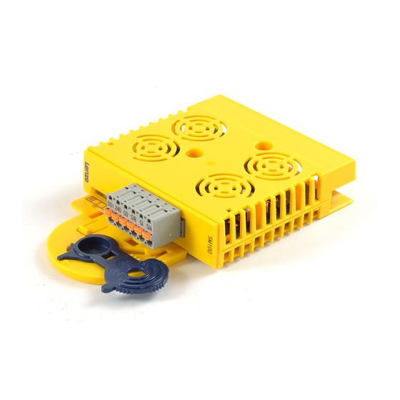
Contenido del suministro Pos. Descripción Módulo de seguridad SM100, tipo E94AYAB Instrucciones para el montaje Elementos en la parte delantera Pos. Descripción Regleta de bornes enchufable para señales de entrada y salida Indicadores Pos. Color Estado Descripción encendido Convertidor habilitado amarillo apagado Mensaje no seguro «Inhibición de impulsos segura»... -
Página 41: Identificación
Identificación ‚ ƒ „ E94YCEI003C E94AYXX001 Serie de producto Versión del equipo Identificación del módulo: Módulo de equipo Tipo de módulo: Módulo de seguridad Ejecución A = SM0 B = SM100 D = SM300 E = SM301 Versión de hardware Versión de software (sólo SM30x) Número de serie ... - Página 42 Validez Este manual es de aplicación para ƒ Módulos de seguridad SM100 a partir de la denominación en la placa de características Type E94AYAB – Posibilidades de uso Estos accesorios sólo se pueden utilizar con ƒ Módulo de eje E94AxxExxxx a partir de la denominación en la placa de características Type E94AxxExxxx...
-
Página 43: Definición De Las Instrucciones Utilizadas
Instrucciones de seguridad Definición de las instrucciones utilizadas Instrucciones de seguridad Definición de las instrucciones utilizadas Para indicar peligros e información importante, se utilizan en esta documentación los siguientes términos indicativos y símbolos: Instrucciones de seguridad Estructura de las instrucciones de seguridad: ... - Página 44 Instrucciones de seguridad Definición de las instrucciones utilizadas Instrucciones de seguridad y de uso especiales para UL y UR Pictograma y término indicativo Significado Instrucción de seguridad o de uso para la utilización de un equipo con aprobación UL en instalaciones con aprobación UL. Warnings ! Posiblemente el sistema de accionamiento no funcionará...
-
Página 45: Instrucciones Generales De Seguridad
Instrucciones de seguridad Instrucciones generales de seguridad Instrucciones generales de seguridad ¡Peligro! La manipulación inadecuada del módulo y del equipo básico puede ocasionar graves daños personales y materiales. Observe siempre las instrucciones de seguridad y sobre peligros residuales incluidas en las instrucciones del equipo básico. ... - Página 46 Instrucciones de seguridad Instrucciones de seguridad para la instalación según UL o UR ¡Aviso! La entrada en el código C00214 debe corresponder al tipo del módulo de seguridad conectado. En caso contrario el convertidor emitirá el error: ”Módulo de seguridad equivocado”. Instrucciones de seguridad para la instalación según U ...
-
Página 47: Datos Técnicos
Datos técnicos Datos técnicos Función ƒ Par con desconexión segura (antes: Paro seguro, protección contra rearranque imprevisto) Datos nominales entrada (sensor) Tipo Voltaje U Corriente I máx E94AYAB - SM100 Datos nominales salida (realimentación) Tipo Voltaje U Corriente I máx E94AYAB - SM100 ... -
Página 48: Montaje
Instalación mecánica Montaje Instalación mecánica Montaje E94AYAX001 EDK94AYAB DE/EN/FR/ES/IT 2.0... -
Página 49: Instalación Mecánica
Instalación mecánica Desmontaje Desmontaje E94AYCXX001H EDK94AYAB DE/EN/FR/ES/IT 2.0... -
Página 50: Instalación Eléctrica
Instalación eléctrica Diagrama en bloque Instalación eléctrica ¡Aviso! Respetar las instrucciones de la documentación del convertidor durante la instalación. Diagrama en bloque SM 100 µC SSP94S1010 SM100 Módulo de seguridad I1A, I2B, GI Conexiones señal de sensor, 2 canales (antigua marcación hasta versión de HW Px: SI1, SI2, GI) 24O, DO1, GO Conexión, respuesta, no seguro... -
Página 51: Datos De Conexión
Instalación eléctrica Datos de conexión Datos de conexión Marcación Descripción Datos eléctricos Entrada primer canal de SI1: I 160 mA tipo= desconexión Potencial GND para SI1/SI2 LOW: -3 ... 5 V, HIGH: 15 ... 30 V, Entrada segundo canal de SI2: I 28 mA tipo=... -
Página 52: Oggetto Della Fornitura
Oggetto della fornitura Pos. Descrizione Modulo di sicurezza SM100, Tipo E94AYAB Istruzioni di montaggio Elementi sul lato anteriore Pos. Descrizione Morsettiera estraibile per segnali di ingresso e uscita Indicazioni luminose Pos. Colore Stato Descrizione acceso Abilitazione controllo giallo spento Inibizione impulsi sicura (segnalazione non sicura) Il modulo non è... - Página 53 Identificazione ‚ ƒ „ E94YCEI003C E94AYXX001 Serie prodotto Versione dispositivo ID modulo: modulo di espansione Tipo modulo: modulo di sicurezza Esecuzione A = SM0 B = SM100 D = SM300 E = SM301 Versione hardware Versione software (solo SM30x) Numero di serie ...
- Página 54 Validità La presente documentazione è valida per ƒ Moduli di sicurezza SM100 a partire dalla versione seguente (vedere targhetta) Type E94AYAB – Compatibilità Questo accessorio può essere utilizzato solo con ƒ Modulo asse E94AxxExxxx a partire dalla versione seguente (vedere targhetta) Type E94AxxExxxx 1.10...
-
Página 55: Simbologia Delle Note E Avvertenze Utilizzate
Informazioni sulla sicurezza Simbologia delle note e avvertenze utilizzate Informazioni sulla sicurezza Simbologia delle note e avvertenze utilizzate Per segnalare pericoli ed informazioni importanti, nella presente documentazione sono riportati i seguenti simboli e parole di segnalazione: Note di sicurezza Struttura delle note di sicurezza: ... - Página 56 Informazioni sulla sicurezza Simbologia delle note e avvertenze utilizzate Note di sicurezza e istruzioni d’uso speciali per UL e UR Simbolo e parola di segnalazione Significato Nota di sicurezza o istruzioni d’uso per il funzionamento di un dispositivo con omologazione UL in impianti omologati UL. ...
- Página 57 Informazioni sulla sicurezza Note generali di sicurezza Note generali di sicurezza Pericolo! L’utilizzo non conforme del modulo e del modulo asse può provocare gravi danni a persone e cose. Osservare le note di sicurezza e pericolo contenute nel manuale del modulo asse.
- Página 58 Informazioni sulla sicurezza Informazioni sulla sicurezza per l’installazione secondo la normativa UL o UR Avvertenza: L’impostazione del codice C00214 deve corrispondere al tipo di modulo di sicurezza collegato. In caso contrario viene segnalato un errore di modulo di sicurezza non valido. Informazioni sulla sicurezza per l’installazione secondo la normativa U ...
-
Página 59: Dati Tecnici
Dati tecnici Dati tecnici Funzione ƒ Scollegamento sicuro: Dati nominali ingresso (sensore) Tipo Tensione U Corrente I E94AYAB - SM100 Dati nominali uscita (retroazione) Tipo Tensione U Corrente I E94AYAB - SM100 EDK94AYAB DE/EN/FR/ES/IT 2.0... - Página 60 Installazione meccanica Montaggio Installazione meccanica Montaggio E94AYAX001 EDK94AYAB DE/EN/FR/ES/IT 2.0...
-
Página 61: Installazione Meccanica
Installazione meccanica Smontaggio Smontaggio E94AYCXX001H EDK94AYAB DE/EN/FR/ES/IT 2.0... -
Página 62: Installazione Elettrica
Installazione elettrica Schema a blocchi Installazione elettrica Avvertenza: Durante l’installazione, consultare la documentazione dell’unità di controllo. Schema a blocchi SM 100 µC SSP94S1010 SM100 Modulo di sicurezza I1A, I2B, GI Collegamenti segnale sensore, a 2 canali (precedente siglatura fino alla versione HW Px: SI1, SI2, GI) 24O, DO1, GO Collegamenti retroazione, non sicuri μ... - Página 63 Installazione elettrica Specifiche dei collegamenti Specifiche dei collegamenti Siglatura Descrizione Dati elettrici Primo ingresso percorso di SI1: I 160 mA tip= disinserzione Potenziale GND per SI1/SI2 LOW: -3 ... 5 V, HIGH: 15 ... 30 V, Secondo ingresso percorso di SI2: I 28 mA tip=...
- Página 64 Lenze Drive Systems GmbH EDK94AYAB Hans-Lenze-Straße 1 DE/EN/FR/ES/IT 2.0 D-31855 Aerzen © 04/2007 Germany TD29 +49 (0) 51 54 82-0 Service 00 80 00 24 4 68 77 (24 h helpline) Service +49 (0) 51 54 82-1112 E-Mail Lenze@Lenze.de...