
Manuales relacionados para Pentair POINT FOUR RIU3


Resumen de contenidos para Pentair POINT FOUR RIU3
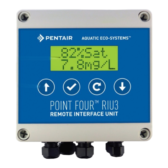
- Página 1 POINT FOUR™ RIU3™ REMOTE MONITOR/CONTROLLER INSTALLATION AND USER’S GUIDE IMPORTANT SAFETY INSTRUCTIONS READ AND FOLLOW ALL INSTRUCTIONS SAVE THESE INSTRUCTIONS...
-
Página 2: Tabla De Contenido
CUSTOMER SERVICE / TECHNICAL SUPPORT If you have questions about ordering Pentair Aquatic Eco-Systems replacement parts, and products, please use ® the following contact information: Customer Service (8 A.M. to 4:30 P.M. — Eastern Technical Support and Pacific Times) Apopka, Florida (8 A.M. to 4:30 P.M. ET) -
Página 3: Overview
%Sat or mg/L 1OXSP001 Optical DO In-Situ %Sat or mg/L 4-20 mA 1ISRD001 Temperature OxyGuard DegC 4-20 mA 1OXSP602 Temperature Pentair DegC 1PTPR010 Pentair TGP (mmHg, %, ΔP), BP (mmHg) mV 1SSP0021 Sensorex 4-20 mA 1SXS8000pH Sensorex 4-20 mA 1SXS8000 Salinity... -
Página 4: System Components
SYSTEM COMPONENTS System Components: System Specifications: 1) RIU LCD Display: 4 x 20 Backlit Alpha Numeric 1) Power: 12-24 VDC, 180 mA max 2) 4-Button Foil Switch 2) Auxiliary power for loop-powered probes: Onboard isolated 24 VDC loop power supply 3) PG9 Cable Gland for Probe Input 3) Input: Inputs are factory-configurable for probes 4) PG9 Cable Glands for Power and Data connections (x2) -
Página 5: System Wiring
SYSTEM WIRING 1. Ch1 input connector i. A 2 pin connector for the first channel for a probe input. Required only for certain probe types, such as a Dissolved Oxygen / Temperature probe. 2. Ch2 input connector i. A 2 pin connector for the second channel for a probe input. Required only for probes with multiple channels, such as a Dissolved Xxygen / Temperature probe. -
Página 6: Typical Riu Wiring Configurations
TYPICAL RIU WIRING CONFIGURATIONS Typical RIU Wiring Configurations 1. Wiring for use with PT4 LC or other SCADA system 2. Wiring for use with a PC WARNING: If the Data and Power wires are not connected to the appropriate terminals, damage to the RIU3 may occur. This will void the warranty. -
Página 7: Riu3 Front Panel
RIU3 FRONT PANEL 1. LCD Display i. A 2x8 Backlit LCD display. 2. “Up” Button i. Scrolls up through menu options or input characters, or in the main menu, toggles between display parameters. 3. “Down” Button i. Scrolls up through menu options or input characters, or in the main menu, toggles between display parameters. 4. -
Página 8: Typical Riu System Setup
TYPICAL RIU SYSTEM SETUP Single Unit Network Diagram Multiple Unit Network Diagram Guide POINT FOUR™ RIU3™ Remote Monitor/Controller Installation and User’s... -
Página 9: Main Display
RIU3 OPERATION The main screen of the RIU3 displays the current values read from the probe. Using the up and down keys toggles between additional probe values and shows the status of the relays either being on or off. Warnings conditions are also displayed on the Main screen Holding down the return arrow for three seconds brings you into the settings menu. -
Página 10: Selection Menu
SELECTION MENU SELECT: External Chs External Chs Calibration SELECT: Calibration Control SELECT: Control Diags SELECT: Diags Setup SELECT: Setup Main Display SELECT: Exit IF YOU DO NOT TOUCH ANY PRESS THE RETURN BUTTON KEYS AFTER 60SEC THE UNIT FROM ANY SCREEN WILL REVERT TO THE WITHIN THE DASHED LINE MAIN DISPLAY... - Página 11 EXTERNAL CH MENU External channels are values required Enter EXT value SET CH: by the RIU3 that it does not produce. (CH Value Displayed) Example: BP is a required input value for an RIU3 con gured for DO readings Enter EXT value Other EXT Chs displayed if any Exit...
-
Página 12: Calibration Sub Menu
CALIBRATION MENU Calibration CAL CH: Sub Menu (Process Variable) Other Cal Chs displayed Calibration if any Sub Menu CAL CH: Menu Selection Exit Calibration Sub Menu: Example of selected Ch displayed mg/L 1 Point Calibration 1 Pt Cal Procedure mg/L 2 Point Calibration 2 Pt Cal Procedure... -
Página 13: Control Menu
CONTROL MENU Select Control Block: Control Block channel: Sensor name toggled every second with engineering units In this example: “Oxy” / “mg/L” Con gure Control Block 1: Oxy / mg/L Other Control Blocks Con gure displayed if any Control Block Menu Selection Exit PRESS THE RETURN BUTTON... -
Página 14: Con Gure Control Block
CONTROL MENU Con gure Control Block: Type Type < Control Control / Alarm Ch In Ch In < Oxy / mg/L Oxy/%Sat Relay Relay < Relay 1 Relay 1 Changing the Values View / change: 1: Hi SP High Setpoint High Setpoint ###ay2 Press the up or down arrow to change the value (0-9) -
Página 15: Diagnostics Menu
DIAGNOSTICS MENU Ch1: mV Values Ch2: mV Values Ch 2 mV pass/fail Status Total Modbus (Net) messages COM 1 & 2 pass/fail Status Total Modbus (Net) errors I2C BUS pass/fail Status Keypad pass/fail Status EEPROM pass/fail Status Relay pass/fail Status pass/fail Status Ch 1 mV pass/fail Status... -
Página 16: Setup Menu
SETUP MENU View / change: SETUP Net ID Net ID SETUP View / change: Backlight Backlight options View / change: SETUP Low Voltage Low Voltage SW REV RIU0### SETUP Menu Selection Exit PRESS THE RETURN BUTTON FROM ANY SCREEN WITHIN THE DASHED LINE TO REVERT TO THE SELECTION MENU Page 10... -
Página 17: Control Block Operation
CONTROL BLOCK OPERATION The RIU3 control blocks take inputs from the probe parameters and control the state of the relays according to some user-selected set points. The user can configure the input parameters, control type, set points, delays and output relays for each control block. The user-selectable parameters are described in more detail below. User-Selectable Control Block Parameters 1) Type: The Type can be set either to Control or Alarm. - Página 18 2) Ch In: This is the input parameter for the control block. The user will have the option to select from all available parameters for the specific probe being used. 3) Relay: This is the output relay for the control block. The user will have the option to select between Relay 1 and Relay 2.
-
Página 19: Probe Calibration
PROBE CALIBRATION The calibration procedure will vary depending on the type of probe being used. In general, either 1-point or 2-point calibrations can be done. Depending on the probe type, 1 or 2 –point calibrations may be recommended. PV=(V_raw-Offset)×Slope PV : Process variable – this is the value that is displayed on the main screen with the appropriate engineering units. Vraw : Raw voltage input –... - Página 20 b. Temperature Calibration The temperature channel is factory calibrated and in general, should never need to be re-calibrated. A 1-point calibration may be completed to ensure consistent readings between different probes. A 2-point calibration may also be completed; however, this can be time consuming and will typically not be as accurate as the existing factory calibration.
-
Página 21: Maintenance Instructions
APPENDIX Appendix A: Specific Probe Manuals Dissolved Oxygen Probe Maintenance Instructions Guide POINT FOUR™ RIU3™ Remote Monitor/Controller Installation and User’s... - Página 22 Membrane Replacement The probe's membrane should be wiped clean from time to time. Membrane replacement should only be performed if: • The membrane is damaged • After long use (years), you cannot calibrate up to the correct value • The probe is not completely full. To replace the membrane proceed as follows.
- Página 23 7) Locate the flat machined from the thread. Lower the upper part into the cap and turn the cap half a turn to engage the thread. 8) Tilt the probe 15° so that the flat is uppermost and screw the cap onto the top part.
-
Página 24: Fault Finding
Fault-Finding Unstable Measurements The most probable cause of unstable measurements in a new installation is that the probe is placed over a diffuser! If the probe has worked well for a long time renovate it. Instability can also be caused by the probe being not completely filed with electrolyte, in which case renovation is indicated. - Página 25 NOTES...
- Página 26 Pentair Aquatic Eco-Systems. Those names and brands may be the trademarks or registered trademarks of those third parties.
-
Página 27: Del Usuario
POINT FOUR™ RIU3™ MONITOR/CONTROLADOR REMOTO GUÍA DE INSTALACIÓN Y DEL USUARIO INSTRUCCIONES IMPORTANTES DE SEGURIDAD LEA Y SIGA TODAS LAS INSTRUCCIONES GUARDE ESTAS INSTRUCCIONES... - Página 28 SERVICIO AL CLIENTE / SOPORTE TÉCNICO Si tiene consultas acerca de cómo pedir partes de repuesto y productos de Pentair Aquatic Eco-Systems, use la siguiente información de contacto: Servicio al cliente (8 a. m. a 4:30 p. m. hora del Soporte Técnico...
-
Página 29: Resumen
Medición óptica de oxígeno disuelto (DO) In-Situ % Sat o mg/L 4-20 mA 1ISRD001 Temperatura OxyGuard °C 4-20 mA 1OXSP602 Temperatura Pentair °C 1PTPR010 Presión total de gases disueltos (TGP) Pentair TGP (mmHg, %, ΔP), BP (mmHg) mV 1SSP0021 Sensorex 4-20 mA 1SXS8000pH... -
Página 30: Componentes Del Sistema
COMPONENTES DEL SISTEMA Componentes del sistema: Especificaciones del sistema: Pantalla LCD de la RIU: 4 x 20, alfanumérica, retroiluminada Alimentación: 12-24 VCC, 180 mA máx Conmutador de 4 teclas Alimentación auxiliar para sondas de alimentación por lazo: Fuente de alimentación de lazo interna, aislada de Prensacable PG9 para entrada de sonda 24 VCC Prensacables PG9 para conexiones de alimentación y datos... -
Página 31: Cableado Del Sistema
CABLEADO DEL SISTEMA Conector de entrada del canal 1 Conector de entrada del canal 2 Salida de alimentación auxiliar de 24 VCC para sondas Entrada auxiliar de sonda RS485 Conectores de entrada RS485 y alimentación Indicadores LED del estado de Tx y Rx de datos Conectores de salida de relé... -
Página 32: Configuraciones Típicas Del Cableado De La Riu
CONFIGURACIONES TÍPICAS DEL CABLEADO DE LA RIU Configuraciones típicas del cableado de la RIU 1. Cableado para el uso con PT4 LC u otro sistema SCADA 2. Cableado para el uso con una PC ADVERTENCIA: Si los cables de datos y de alimentación no se conectan a los terminales apropiados, la RIU3 puede sufrir daños. -
Página 33: Panel Frontal De La Riu3
PANEL FRONTAL DE LA RIU3 Pantalla LCD retroiluminada Botón «Up» Botón «Enter» Botón «Return» Botón «Down» 1. Pantalla LCD i. Pantalla LCD retroiluminada de 2 x 8 2. Botón «Up» i. Permite desplazarse por el menú de opciones o ingresar caracteres o, en el menú principal, alternar entre los parámetros de la pantalla. -
Página 34: Configuración Típica Del Sistema De La Riu
CONFIGURACIÓN TÍPICA DEL SISTEMA DE LA RIU Diagrama de red de unidad autónoma Relé #1 Control Luz de alarma del sistema Relé #2 Control Distribuidor de medidor de caudal Sonda Alimentación Enlace de datos Diagrama de red de unidad múltiple ™... -
Página 35: Funcionamiento De La Riu3
FUNCIONAMIENTO DE LA RIU3 La pantalla principal de la RIU3 muestra la lectura de los valores actuales de la sonda. Las teclas «Up» y «Down» permiten alternar entre los valores adicionales de sonda y mostrar el estado de los relés, ya sea abierto (on) o cerrado (off). -
Página 36: Menú De Selección
MENÚ DE SELECCIÓN SELECCIONAR: Canales externos Canales externos SELECCIONAR: Calibración Calibración SELECCIONAR: Control Control SELECCIONAR: Diagnósticos Diagnósticos SELECCIONAR: Configuración Configuración SELECCIONAR: Pantalla principal Salida OPRIMA LA TECLA «RETURN» DESDE CUALQUIER PANTALLA SI NO TOCA NINGUNA TECLA, AL CABO DENTRO DE LA LÍNEA DISCONTÍNUA DE 60 SEG LA UNIDAD REGRESARÁ... -
Página 37: Menú De Canales Externos
MENÚ DE CANALES EXTERNOS Los canales externos son valores que la RIU3 requiere y que esta no AJUSTAR CANAL: Introducir valor EXT produce. (Valor de canal mostrado) Ejemplo: BP (presión barométrica) es un valor de entrada requerido por una RIU3 que está configurada para Se muestran otros lecturas de DO... -
Página 38: Submenú De Calibración
MENÚ DE CALIBRACIÓN Submenú de CANAL de CALIBRACIÓN: calibración (Variable de proceso) Se muestran otros Submenú de canales de calibración calibración si existen CANAL de CALIBRACIÓN: Salida Menú de selección Submenú de calibración: Ejemplo de canal seleccionado mostrado mg/L Calibración de 2 puntos Calibración de 1 pt. - Página 39 MENÚ DE CONTROL Seleccionar bloque de control: Canal de bloque de control: El nombre del sensor se alterna cada segundo con las unidades técnicas En este ejemplo: “Oxy” / “mg/L” Configurar 1: Oxy / mg/L Bloque de control Otros bloques de control Configurar se muestran si existen Bloque de control...
-
Página 40: Menú De Control
MENÚ DE CONTROL Seleccionar bloque de control: < Tipo Tipo Control Control / Alarma Ch In Ch In < Oxy / mg/L Oxy/%Sat Relé Relé < Relé 1 Relé 1 Changing the Values Ver / Cambiar: 1: Hi SP Punto de ajuste alto Punto de ajuste alto ###ay2 Oprima las flechas verticales hacia arriba o hacia abajo para cambiar el valor (0-9). -
Página 41: Menú De Diagnóstico
MENÚ DE DIAGNÓSTICO Ch1: Valores en mV Ch2: Valores en mV Ch 2 mV estado de falla/ aprobación Mobdus total Mensajes (netos): COM 1 y 2 estado de falla/ aprobación Mobdus total Errores (netos) BUS I2C estado de falla/ aprobación Teclado estado de falla/ aprobación... -
Página 42: Configuración
CONFIGURACIÓN Ver / Cambiar: CONFIGURACIÓN ID de red ID de red Ver / Cambiar: CONFIGURACIÓN Opciones de Backlight retroiluminación Ver / Cambiar: CONFIGURACIÓN Bajo voltaje Bajo voltaje SW REV RIU0### CONFIGURACIÓN Menú de selección Salida OPRIMA LA TECLA «RETURN» DESDE CUALQUIER PANTALLA DENTRO DE LA LÍNEA DISCONTÍNUA PARA REGRESAR AL MENÚ... -
Página 43: Funcionamiento Del Bloque De Control
FUNCIONAMIENTO DEL BLOQUE DE CONTROL Los bloques de control de la RIU3 toman entradas de los parámetros de la sonda y controlan el estado de los relés de acuerdo con los puntos de ajuste que haya establecido el usuario. El usuario puede configurar los parámetros de entrada, tipo de control, puntos de ajuste, relés de salida y retardo para cada bloque de control. - Página 44 2) Ch In: Este es el parámetro de entrada para el bloque de control. El usuario tendrá la opción de seleccionar entre todos los parámetros disponibles para la sonda específica que se está usando. 3) Relay: Este es el relé de salida para el bloque de control. El usuario tendrá la opción de seleccionar entre el relé 1 y el relé...
-
Página 45: Calibración De Tipos Específicos De Sonda
CALIBRACIÓN DE LA SONDA El procedimiento de calibración varía según el tipo de sonda que se esté utilizando. En general, se pueden hacer calibraciones de 1 o 2 puntos. Según el tipo de sonda, se recomiendan calibraciones de 1 o 2 puntos. PV=(V_raw-Offset)×Slope PV : Variable de proceso: este es el valor que se muestra en la pantalla principal con las unidades técnicas apropiadas. - Página 46 b. Calibración de temperatura El canal de temperatura viene calibrado de fábrica y, por lo general, nunca necesitaría ser recalibrado. Se puede hacer una calibración de 1 punto para garantizar la consistencia de las lecturas entre varias sondas diferentes. También se puede hacer una calibración de 2 puntos; sin embargo, esto puede llevar mucho tiempo y por lo general no será...
-
Página 47: Sonda De Oxígeno Disuelto
APÉNDICE Apéndice A: Manuales de sondas específicas Sonda de oxígeno disuelto Instrucciones de mantenimiento ™ ™ Guía del usuario y de instalación de monitor/controlador remoto POINT FOUR RIU3... -
Página 48: Reemplazo De La Membrana
Reemplazo de la membrana Las membranas de las sondas se deben limpiar de vez en cuando. La membrana se debe reemplazar en los siguientes casos: • La membrana se ha dañado. • Después de un tiempo prolongado de uso (años), no se puede calibrar al valor correcto. - Página 49 7) Localice el drenaje en la rosca. Baje la parte de arriba hacia la tapa y gire la tapa media vuelta para que se enrosque. 8) Incline la sonda 15° para que el drenaje quede hacia arriba y atornille la tapa en la parte superior. El exceso de electrolito y el aire saldrán por el drenaje.
- Página 50 Localización de averías Mediciones inestables La causa más probable de mediciones inestables en una instalación nueva es que la sonda esté colocada sobre un difusor. Si la sonda ha funcionado bien durante mucho tiempo, debe cambiarla. La inestabilidad también puede generarse cuando la sonda no está totalmente llena de electrolitos, en cuyo caso se indica una renovación.
- Página 51 NOTAS...
- Página 52 2395 APOPKA BLVD., APOPKA, FL 32703 • US (877) 347-4788 • INT. (407) 886-3939 WWW.PENTAIRAES.COM Todas las marcas comerciales y los logos de Pentair son propiedad de Pentair o de una de sus empresas globales asociadas. Pentair Aquatic Eco-Systems , Point Four™ y RIU3™ son marcas comerciales y/o marcas registradas de Pentair Aquatic Eco-Systems y/o sus empresas afiliadas en ®...