
Manuales relacionados para Gewiss Chorus GW 10 763


Resumen de contenidos para Gewiss Chorus GW 10 763
- Página 1 Termostato Easy - da parete Easy wall thermostat Thermostat Easy - mural Termostato Easy - de pared Easy Thermostat für Wandmontage GW 10 763 GW 14 763...
-
Página 3: Tabla De Contenido
INDICE pag. AVVERTENZE GENERALI Contenuto della confezione ................DESCRIZIONE GENERALE In breve ......................Posizione dei comandi..................Descrizione comandi..................Modalità di controllo..................Modalità di funzionamento ................ISTRUZIONI D’IMPIEGO Impostazione parametri..................10 Reset e ripristino dei valori preimpostati............20 Forzatura temporanea della temperatura............20 Parametri preimpostati.................. -
Página 4: Avvertenze Generali
L’organizzazione di vendita GEWISS è a disposizione per chiarimenti e informazioni tecniche. Gewiss SpA si riserva il diritto di apportare modifiche al prodotto descritto in questo manuale in qualsiasi momento e senza alcun preavviso. Contenuto della confezione n. -
Página 5: Descrizione Generale
DESCRIZIONE GENERALE In breve Il Termostato Easy - da parete consente di gestire la temperatura dell’ambiente in cui è installato. La regolazione della temperatura viene effettuata comandando, attraverso il bus KNX/EIB del sistema di Home Automation, gli attuatori KNX/EIB che controllano gli elementi di riscaldamento o condizionamento, compresi i fan coil. -
Página 6: Posizione Dei Comandi
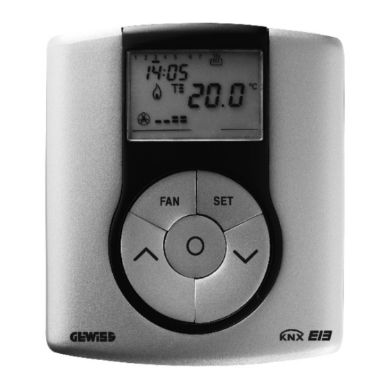
DESCRIZIONE GENERALE Posizione dei comandi Il termostato è dotato di un display LCD retroilluminato e di cinque pulsanti di comando sempre accessibili. -
Página 7: Descrizione Comandi
DESCRIZIONE GENERALE Descrizione comandi PULSANTI DI COMANDO Simbolo Pag. Regolazione velocità fan coil Regolazione temperatura (+) / Selezione parametri Selezione modalità funzionamento / conferma Regolazione temperatura (–) / Selezione parametri Impostazione parametri SEGNALAZIONI A DISPLAY Modalità di funzionamento automatico del fan coil collegato AUTO Modalità... -
Página 8: Modalità Di Controllo
DESCRIZIONE GENERALE Modalità di controllo Il termostato può essere impostato in 2 differenti modalità di controllo: • Slave: il funzionamento dipende dal dispositivo configurato come Master (ad esempio il cronotermostato EIB Easy GW 10 761), che imposta tipo e modalità di funzionamento del termostato. - Página 9 DESCRIZIONE GENERALE SIGNIFICATO DI Riscaldamento Condizionamento Simbolo Modalità Modalità Set point Set point funzionamento funzionamento Economy Comfort ECONOMY COMFORT Precomfort Precomfort PRECOMFORT PRECOMFORT Comfort Economy COMFORT ECONOMY Il funzionamento antigelo è attivo solo in riscaldamento, a impianto di termoregolazione spento (OFF). In questo caso il termostato utilizza il set point di temperatura antigelo impostato, riattivando l’impianto di riscaldamento solo se la temperatura ambientale...
-
Página 10: Istruzioni D'impiego
ISTRUZIONI D IMPIEGO Durante il funzionamento, l’attivazione del riscaldamento o del condizionamento sono segnalate nel modo seguente: Riscaldamento Il simbolo indica che il comando di attivazione è stato inviato all’attuatore di comando della caldaia o dell’elettrovalvola di zona. Se il termostato non riceve dall’attuatore il riscontro dell’avvenuta attuazione, il simbolo inizia a lampeggiare. - Página 11 ISTRUZIONI D IMPIEGO È possibile impostare i seguenti parametri: Tipo di funzionamento (riscaldamento/condizionamento) Giorno della settimana Minuti Unità di misura della temperatura A questo punto, secondo il tipo di funzionamento, è possibile modificare in sequenza: Riscaldamento Condizionamento - Set Point - Set Point risc cond...
- Página 12 ISTRUZIONI D IMPIEGO Selezione riscaldamento/condizionamento Quando il simbolo lampeggia, è possibile selezionare il tipo di funzionamento con i tasti Per confermare la scelta, premere il tasto entro 30 secondi. Impostazione del giorno della settimana Quando la barra del giorno della settimana lampeggia, selezionare il giorno corrente con i tasti (lunedì=1, martedì=2 …...
- Página 13 ISTRUZIONI D IMPIEGO - Impostazione Set Point (riscaldamento) risc All’apparire del simbolo , il valore di temperatura inizia a lampeggiare. Regolare il valore di ECONOMY con i tasti Per confermare il valore impostato, premere il tasto entro 30 secondi. - Impostazione Set Point (condizionamento) cond All’apparire del simbolo...
- Página 14 ISTRUZIONI D IMPIEGO - Impostazione Set Point (riscaldamento) risc All’apparire del simbolo , il valore di temperatura inizia a lampeggiare. Regolare il valore di COMFORT con i tasti Per confermare il valore impostato, premere il tasto entro 30 secondi. - Impostazione Set Point (condizionamento) cond All’apparire del simbolo...
- Página 15 ISTRUZIONI D IMPIEGO P05 - Logica di controllo All’apparire della scritta P05, impostare la logica di controllo dell’impianto di termoregolazione con i tasti (00 = controllo a 2 punti, 01 = controllo proporzionale (PWM), 02 = controllo fan coil) Per confermare il valore impostato, premere il tasto entro 30 secondi.
- Página 16 ISTRUZIONI D IMPIEGO CONTROLLO PROPORZIONALE (PWM) La banda proporzionale (da set point a set point - per il riscaldamento, da set point a set point + per il condizionamento) viene divisa in quattro zone uguali. Il termostato controlla, al termine di ogni tempo di ciclo, la temperatura ambientale e, in base alla differenza riscontrata, modula la proporzione dei comandi ON e OFF trasmessi durante il tempo di ciclo.
- Página 17 ISTRUZIONI D IMPIEGO CONTROLLO FAN COIL Quando la temperatura raggiunge il valore set point- (in riscaldamento), o set point+ (in condizionamento), viene inviato un messaggio di ON per l'attivazione del fan coil nel tipo di funzionamento selezionato e un messaggio di ON per l'accensione della ventola del fan coil stesso a velocità...
- Página 18 ISTRUZIONI D IMPIEGO Per evitare continue commutazioni, il termostato può attendere fino a 2 minuti prima di inviare il comando di attivazione all’attuatore che controlla l’impianto di termoregolazione o ai canali dell’attuatore che comandano le velocità del fan coil. P06 - Impostazione tempo di ciclo All’apparire della scritta P06, impostare la lunghezza del tempo di ciclo con i tasti I possibili valori sono: 5, 10, 20, 30, 40, 50, 60 minuti.
- Página 19 ISTRUZIONI D IMPIEGO P09 - Impostazione modalità di controllo All’apparire della scritta P09, impostare la modalità di controllo del termostato con i tasti (00 = SLAVE, 01 = STAND ALONE) Per ulteriori informazioni vedere il paragrafo Modalità di controllo. Se si è scelta la modalità SLAVE la programmazione è terminata.
-
Página 20: Reset E Ripristino Dei Valori Preimpostati
ISTRUZIONI D IMPIEGO Forzatura temporanea della temperatura Nelle modalità di funzionamento Economy, Precomfort e Comfort è possibile forzare temporaneamente il set point di temperatura attivo, utilizzando i tasti per impostare il valore desiderato. Confermare il valore premendo il tasto o attendere 5 secondi. L’attivazione della forzatura viene segnalata sul display dal lampeggio di Nel caso di modalità... -
Página 21: Parametri Preimpostati
ISTRUZIONI D IMPIEGO Parametri preimpostati Giorno della settimana 1: lunedì 00:00 Set point temperatura di riscaldamento 16 °C 18 °C 20 °C 5 °C ANTIGELO Set point temperatura di condizionamento 24 °C 26 °C 28 °C 35 °C PROTEZIONE ALTE TEMPERATURE Unità... -
Página 22: Comportamento Alla Caduta E Al Ripristino Dell'alimentazione Bus
ISTRUZIONI D IMPIEGO Comportamento alla caduta e al ripristino dell’alimentazione bus Alla caduta dell’alimentazione bus il dispositivo non compie alcuna azione. Ora e data sono mantenute dall’alimentazione tampone (batteria ricaricabile), mentre tutte le altre impostazioni sono conservate in una memoria non volatile. Con alimentazione fornita esclusivamente dalla batteria si ha un’autonomia di 36 ore nelle seguenti condizioni: •... -
Página 23: Sostituzione Batteria
ISTRUZIONI D IMPIEGO Sostituzione batteria Togliere la vite di fissaggio, che si trova sotto il dispositivo, e staccare il termostato dalla base di supporto, seguendo la sequenza illustrata in figura. Togliere il coperchietto di chiusura del vano batteria e sostituire la batteria ricaricabile con un’altra dello stesso tipo (ML1220) rispettando le polarità... -
Página 24: Pulizia Del Termostato
ISTRUZIONI D IMPIEGO Riagganciare il termostato sulla base di supporto, seguendo la sequenza illustrata in figura, e fissarlo nuovamente con la vite posta sotto il dispositivo. ATTENZIONE - Se il termostato non è stato alimentato dal bus durante la sostituzione della batteria, riaggiornare data e ora. -
Página 25: Istruzioni D'installazione
ISTRUZIONI D INSTALLAZIONE ATTENZIONE: l’installazione del dispositivo deve essere effettuata esclusivamente da personale qualificato, seguendo la normativa vigente e le linee guida per le installazioni KNX/EIB. Corretto posizionamento Per la corretta rilevazione della temperatura dell’ambiente controllare, il termostato non deve essere installato in nicchie, vicino a porte finestre,... -
Página 26: Avvertenze Per L'installazione Knx/Eib
ISTRUZIONI D INSTALLAZIONE Montaggio su scatola tonda (o quadrata) Avvertenze per l’installazione KNX/EIB 1. La lunghezza della linea bus tra il termostato Easy e l’alimentatore non deve superare i 350 metri. 2. La lunghezza della linea bus tra il termostato Easy e il più lontano dispositivo KNX/EIB da comandare non deve superare i 700 metri. -
Página 27: Connessioni Elettriche
ISTRUZIONI D INSTALLAZIONE ATTENZIONE: i cavi di segnale del bus non utilizzati e il conduttore di continuità elettrica non devono mai toccare elementi sotto tensione o il conduttore di terra. Connessioni elettriche Schema delle connessioni elettriche 1. Prima di procedere alla connessione al bus KNX/EIB, inserire la batteria ricaricabile per la memoria tampone (vedere paragrafo Sostituzione batteria). -
Página 28: Inizializzazione Con Unità Base Easy
ISTRUZIONI D INSTALLAZIONE 4. Inserire il morsetto bus negli appositi piedini del dispositivo. Il corretto senso di inserzione è determinato dalle guide di fissaggio. Inizializzazione con unità base Easy 1. Alimentare il dispositivo attraverso il bus e attendere 5 secondi affinché sia completamente operativo. -
Página 29: Completamento
ISTRUZIONI D INSTALLAZIONE Completamento Agganciare il termostato sulla base di supporto, seguendo la sequenza illustrata in figura, e fissarlo con la vite in dotazione. Programmazione con unità base Easy Programmare il termostato tramite l’unità base Easy (codice GW 90 831). Il canale del termostato, da utilizzare nella funzione che si desidera creare, può... - Página 30 ISTRUZIONI D INSTALLAZIONE I canali disponibili nella modalità di programmazione sono: StS (Status - Stato) Da utilizzare per inviare a dispositivi remoti (ad esempio il remotizzatore GSM EIB Easy - GW 90 861): • modalità e tipo di funzionamento; • temperatura misurata (ogni 15 minuti o a ogni sua variazione).
- Página 31 ISTRUZIONI D INSTALLAZIONE Nota bene. I canali Cd1, Cd2 e Cd3 si devono usare solo nel caso di utilizzo del termostato nella modalità di controllo fan coil. Nella creazione delle funzioni sopra indicate non è necessario selezionare alcuna funzione sull’unità base perché il link è creato automaticamente. SLA (Slave) Da utilizzare per impostare: •...
-
Página 32: Dati Tecnici
DATI TECNICI Comunicazione Bus KNX/EIB Alimentazione Tramite bus KNX/EIB, 29 V dc SELV + 1 batteria ricaricabile tipo ML1220 3 V per l’aggiornamento data/ora in caso di assenza tensione bus Assorbimento corrente dal bus 5 mA Cavo bus KNX/EIB TP1 Elementi di comando 5 pulsanti frontali 1 tasto miniatura di programmazione... - Página 33 CONTENTS page GENERAL INFORMATION Pack content ....................34 GENERAL DESCRIPTION Summary......................35 Position of the controls ..................36 Control description ................... 37 Control mode ....................38 Operation mode ....................38 USER INSTRUCTIONS Setting parameters ..................40 Reset and reinstatement of default settings ............50 Temporary temperature forcing ................
-
Página 34: General Information
The GEWISS sales organisation is at your disposal for clarifications and technical information. Gewiss SpA reserves the right to make changes to the product described in this manual at any time and without giving any notice. Pack content n. -
Página 35: General Description
GENERAL DESCRIPTION Summary The wall-mounting Easy Thermostat allows you to manage the temperature in the area it is installed in. The temperature is regulated by the KNX/EIB actuators which are managed by the Home Automation KNX/EIB bus and control the heating or air- conditioning elements, including the fan coils. -
Página 36: Position Of The Controls
GENERAL DESCRIPTION Position of the control keys The thermostat is fitted with a backlit LCD display and 5 control buttons which are always accessible. -
Página 37: Control Description
GENERAL DESCRIPTION Control description CONTROL BUTTONS Symbol Page Fan-coil speed regulation Temperature regulation (+) / select parameters Select operation mode / confirmation Temperature regulation (-) / select parameters Setting parameters DISPLAY SIGNALS Auto operation mode for the connected fan coil AUTO Manual operation mode for the connected fan coil Thermostat in operation mode OFF... -
Página 38: Control Mode
GENERAL DESCRIPTION Control modes The thermostat can be set to 2 different control modes: • Slave: the function depends on the device configured as Master (for instance the Easy EIB timer-thermostat GW 10 761), that set the thermostat operation type and mode. In this function mode the thermostat uses the set-point values that are set locally. - Página 39 GENERAL DESCRIPTION MEANINGS Heating Air conditioning Symbol Operation Operation Set point Set point mode mode Economy Comfort ECONOMY COMFORT Precomfort Precomfort PRECOMFORT PRECOMFORT Comfort Economy COMFORT ECONOMY The frostprotect operation is only enabled in heating operation mode, when the thermal regulation system is OFF.
-
Página 40: User Instructions
USER INSTRUCTIONS The activation of the heating or air-conditioning operations are indicated as followed: Heating symbol indicates that the activation command has been sent to the actuator which controls the boiler or the zone electro-valve. If the thermostat does not receive confirmation from the actuator that the same has been activated, the symbol starts to flash. - Página 41 USER INSTRUCTIONS It is possible to set the following parameters: Operation type (heating/air conditioning) Day of the week Hour Minutes Temperature unit of measurement According to the operation type, it is now possible to sequentially modify: Heating Air conditioning - Set Point - Set Point heat cond...
- Página 42 USER INSTRUCTIONS Selecting heating/air conditioning When the symbol blinks it is possible to select the operation type using the keys . Press the key within 30 seconds to confirm the selection. Setting the day of the week When the day of week bar is blinking, select the current day using the keys.
- Página 43 USER INSTRUCTIONS - Set Point setting (heating) heat The temperature value starts to blink when the symbol appears. Regulate the T value ) using ECONOMY keys. Press the key within 30 seconds to confirm the value set. - Set Point setting (air conditioning) cond The temperature value starts to blink when the...
- Página 44 USER INSTRUCTIONS - Set Point setting (heating) heat The temperature value starts to blink when the , symbol appears. Regulate the ) using the keys. COMFORT Press the key within 30 seconds to confirm the value set. - Set Point setting (air conditioning) cond The temperature value starts to blink when the...
- Página 45 USER INSTRUCTIONS P05 - Control logic When the P05 code appears on the screen, set the thermal regulation control logic using the keys. (00 = 2 point control, 01 = proportional control (PWM), 02 = fan coil control) Press the key within 30 seconds to confirm the value set.
- Página 46 USER INSTRUCTIONS PROPORTIONAL CONTROL (PWM) The proportional channel (from set point to set point - for heating, from set point to set point + air-conditioning) is divided into four equal zones. At the end of each cycle time, the thermostat controls the ambient temperature and, according to the differences recorded, it modulates the proportion of the ON and OFF commands transmitted during the cycle time.
- Página 47 USER INSTRUCTIONS FAN COIL CONTROL When the temperature reaches the set point value- (in heating) or set point+ (in air-conditioning) an ON message is sent to activate the fan coil for the selected operation type, and an ON message to switch on the fan coil at speed V1.
- Página 48 USER INSTRUCTIONS To avoid continuous switchings, the thermostat will wait for up to 2 minutes before sending the activation command to the actuator that controls the thermal regulation system or to the actuator channels that control the fan coil speed. P06 - Setting the cycle time When the P06 code appears on the screen, set the cycle time using the...
- Página 49 USER INSTRUCTIONS P09 - Setting the control mode When the P09 code appears on the screen, set the thermostat control mode using the keys. (00 = SLAVE, 01 = STAND ALONE) For further information, please refer to the Control Mode paragraph.
-
Página 50: Reset And Reinstatement Of Default Settings
USER INSTRUCTIONS Temporary temperature forcing It is possible to temporarily force the active temperature set point in Economy, Precomfort and Comfort operation modes by using the keys to set the required value. Confirm the value by pressing the key or waiting for 5 seconds. will flash on the display to indicate that the forcing is enabled. -
Página 51: Preset Parameters
USER INSTRUCTIONS Preset parameters Day of the week 1: Monday Hour 00:00 Heating temperature set-point 16 °C 18 °C 20 °C 5 °C FROSTPROTECT Air-conditioning temperature set-point 24 °C 26 °C 28 °C 35 °C HIGH TEMPERATURE PROTECTION Temperature unit of measurement °C Control logic 2 points... -
Página 52: Behaviour On The Failure And Reinstatement Of The Bus Power Supply
USER INSTRUCTIONS Behaviour on the failure and reinstatement of the bus power supply When the bus power supply fails, the device performs no actions. The time and date are maintained by the buffer power system (rechargeable battery) whilst all the other settings are saved to a non-volatile memory. When the power is supplied by battery only, the device has an autonomy of 36 hours in the following conditions: •... -
Página 53: Replacing The Battery
USER INSTRUCTIONS Replacing the battery Remove the fastener screws which are under the device, and remove the thermostat from the support base, as seen in the figure below. Remove the battery holder cover and replace the rechargeable battery with one of the same type (ML1220), paying attention to the direction of the poles. -
Página 54: Cleaning The Thermostat
USER INSTRUCTIONS Replace the thermostat in the support base, as seen in the figure below, and replace the screws under the device. WARNING: - If the thermostat was not powered by the bus whilst replacing the battery, update the time and date. - Never throw the battery into a fire. -
Página 55: Installation Instructions
INSTALLATION INSTRUCTIONS WARNING: the installation of the device must be exclusively done by qualified personnel, following the regulations in force and the guidelines for KNX/EIB installations. Correct installation position In order for the thermostat to take correct readings of the ambient temperature, it must not be installed in an alcove, near a door or window, next to radiators or air conditioner... -
Página 56: Warnings For Knx/Eib Installations
INSTALLATION INSTRUCTIONS Mounting on a round (or square) box Warnings for KNX/EIB installations 1. The length of the bus line between the Easy thermostat and the power supply unit must not exceed 350 metres. 2. The length of the bus line between the Easy thermostat and the most distant KNX/EIB device must not exceed 700 metres. -
Página 57: Electrical Connections
INSTALLATION INSTRUCTIONS WARNING: the unused bus signal cables and the electrical continuity conductor must never touch elements under power or the earth conductor. Electrical connections Electrical connections diagram 1. Before connecting the KNX/EIB bus, insert the rechargeable buffer memory battery (see Replacing the Battery paragraph). -
Página 58: Initialization With The Easy Base Unit
INSTALLATION INSTRUCTIONS 4. Insert the bus connector into the special feet of the device. The fastener guides determine the direction it should be inserted. Initialization with the Easy base unit 1. Power up the device using the bus and wait for 5 seconds until it is in full operation mode. -
Página 59: Completing Installation
INSTALLATION INSTRUCTIONS Completing installation Position the thermostat on the support base, as seen in the figure below, and fix it in place using the supplied screws. Programming with the Easy base unit Programming the thermostat through the Easy base unit (code GW 90 831). The thermostat channel to be used in the function that is to be created can be selected at choice: •... - Página 60 INSTALLATION INSTRUCTIONS The channels available in the programming mode are: StS (Status) Used to send to remote devices (for instance the EIB Easy GSM remote control unit - GW 90 861): • operation type and mode: • temperature reading (every 15 minutes or each time it changes).
- Página 61 INSTALLATION INSTRUCTIONS Note. The Cd1, Cd2 and Cd3 channels must only be used when a thermostat is used to control the fan coil. When creating the above listed functions, it is not necessary to select a base unit function as the link is created automatically. SLA (Slave) •...
-
Página 62: Technical Data
TECHNICAL DATA Communication KNX/EIB Bus Power Supply By KNX/EIB, 29 V dc SELV bus + 1 rechargeable ML1220 3 V battery to update date and time when there is a bus power failure Bus current consumption 5 mA Bus cable KNX/EIB TP1 Control elements 5 front buttons... - Página 63 SOMMAIRE page AVERTISSEMENTS GÉNÉRAUX Contenu de la confection .................. 64 DESCRIPTION GÉNÉRALE En bref ......................65 Position des commandes ................. 66 Description des commandes ................67 Modalités de contrôle ..................68 Modes de fonctionnement ................68 INSTRUCTIONS D'UTILISATION Programmation des paramètres ............... 70 Reset et rétablissement des valeurs préréglées ..........
-
Página 64: Avertissements Généraux
L’organisation de vente de la Société GEWISS est à votre disposition pour tous éclaircissements et toutes informations techniques. Gewiss SpA se réserve le droit de faire des modifications sur le produit décrit dans ce manuel, à n’importe quel moment et sans aucun préavis. -
Página 65: Description Générale
DESCRIPTION GÉNÉRALE En bref Le Thermostat Easy - mural permet de gérer la température de la pièce où il est installé. Le thermostat effectue le réglage de la température en commandant, par le biais du bus KNX/EIB du système de Home Automation, les actionneurs KNX/EIB qui contrôlent les éléments de chauffage ou de climatisation, y compris les fan coils. -
Página 66: Position Des Commandes
DESCRIPTION GENERALE Position des commandes Le thermostat est muni d’un afficheur LCD rétro éclairé et de cinq boutons de commande toujours accessibles. -
Página 67: Description Des Commandes
DESCRIPTION GENERALE Description des commandes BOUTONS DE COMMANDE Symbole Page Réglage de la vitesse du fan coil Réglage de la température(+)/Sélection des paramètres Sélection du mode de fonctionnement / confirmation Réglage de la température (-)/Sélection des paramètres Programmation des paramètres SIGNALISATIONS SUR L’AFFICHEUR Mode de fonctionnement automatique du fan coil connecté... -
Página 68: Modalités De Contrôle
DESCRIPTION GENERALE Modalités de contrôle Le thermostat peut être réglé en 2 modalités de contrôle différentes: • Slave: le fonctionnement dépend du dispositif configuré comme Master (par exemple le chronothermostat EIB Easy GW 10 761), qui programme le type et le mode de fonctionnement du thermostat. - Página 69 DESCRIPTION GENERALE SIGNIFICATION DE Chauffage Climatisation Symbole Mode de Mode de Set-point Set-point fonctionnement fonctionnement Économie Confort ÉCONOMIE CONFORT Preconfort Preconfort PRECONFORT PRECONFORT Confort Économie CONFORT ÉCONOMIE Le fonctionnement antigel n’est actif qu’en mode chauffage, et avec l’installation de régulation thermique éteinte (Arrêt).
-
Página 70: Instructions D'utilisation
INSTRUCTIONS D'UTILISATION Pendant le fonctionnement, l’activation du chauffage ou de la climatisation est signalée de la façon suivante: Chauffage Le symbole indique que la commande d’activation a été envoyée à l’actionneur de commande de la chaudière ou de l’électrovanne de zone. Si le thermostat ne reçoit pas de l’actionneur la réponse que l’activation a été... - Página 71 INSTRUCTIONS D'UTILISATION Il est possible de programmer les paramètre suivants: Type de fonctionnement (chauffage/climatisation) Jour de la semaine Heures Minutes Unité de mesure de la température On peut alors, suivant le type de fonctionnement, modifier en séquence: Chauffage Climatisation - Set Point - Set Point chauf climat...
- Página 72 INSTRUCTIONS D'UTILISATION Sélection chauffage/climatisation Lorsque le symbole ou bien clignote, il est possible de sélectionner le type de fonctionnement en agissant sur les touches . Pour confirmer la sélection, appuyer sur la touche avant 30 secondes. Programmation du jour de la semaine Quand la barre du jour de la semaine clignote, sélectionner le jour courant avec les touches (lundi=1, mardi= 2, dimanche=7).
- Página 73 INSTRUCTIONS D'UTILISATION - Programmation du Set-point (chauffage) chauff Quand le symbole , apparaît, la valeur de température commence à clignoter. Régler la valeur de ) avec les touches ÉCONOMIE Pour confirmer la valeur programmée, appuyer sur la touche dans les 30 secondes qui suivent. - Programmation du Set-point (climatisation) climat...
- Página 74 INSTRUCTIONS D'UTILISATION - Programmation du Set-point (chauffage) chauff Quand le symbole apparaît, la valeur de température commence à clignoter. Régler la valeur de CONFORT avec les touches Pour confirmer la valeur programmée, appuyer sur la touche dans les 30 secondes qui suivent. - Programmation du Set-point (climatisation) climat...
- Página 75 INSTRUCTIONS D'UTILISATION P05 - Logique de contrôle Quand le message P 05 apparaît, programmer la logique de contrôle de l’installation de régulation thermique, avec les touches . (00 = contrôle à 2 points, 01 = contrôle proportionnel (PWM), 02 = contrôle fan coil) Pour confirmer la valeur programmée, appuyer sur la touche dans les 30 secondes qui suivent.
- Página 76 INSTRUCTIONS D'UTILISATION CONTRÔLE PROPORTIONNEL (PWM) La bande proportionnelle (du set point jusqu’à set point pour le chauffage, du set point jusqu’à set point pour la climatisation) est divisée en quatre zones égales. A la fin de chaque temps de cycle, le thermostat contrôle la température ambiante et, en fonction de la différence constatée, il module la proportion des commandes Marche et Arrêt transmises pendant le temps du cycle.
- Página 77 INSTRUCTIONS D'UTILISATION CONTRÔLE FAN COIL Quand la température atteint la valeur de set point - (en chauffage) ou bien de set point + climatisation), un message de Marche est envoyé pour l'activation du fan coil dans le type de fonctionnement sélectionné, et un message de Marche pour l'allumage de l'hélice du fan coil à...
- Página 78 INSTRUCTIONS D'UTILISATION Pour éviter des commutations continuelles, le thermostat peut attendre jusqu’à 2 minutes avant d’envoyer la commande d’activation à l’actionneur qui contrôle l’installation de régulation thermique ou aux canaux de l’actionneur qui commandent les vitesses du fan coil. P06 - Programmation du temps de cycle Lorsque le message P06 apparaît, il faut programmer la longueur du temps de cycle avec les touches Les valeurs possibles sont: 5, 10, 20, 30, 40, 50, 60...
- Página 79 INSTRUCTIONS D'UTILISATION P09 - Programmation de la modalité de contrôle Quand le message P09 apparaît, programmer la modalité de contrôle du thermostat, avec les touches (00 = SLAVE, 01 = STAND ALONE) Pour d’autres informations, voir le paragraphe Modalités de contrôle. Si l’on a choisi la modalité...
-
Página 80: Reset Et Rétablissement Des Valeurs Préréglées
INSTRUCTIONS D'UTILISATION Forçage temporaire de la température Dans les modes de fonctionnement Economie, Preconfort et Confort, il est possible de forcer temporairement le set point de température activé, en utilisant les touches pour régler la valeur désirée. ou bien attendre 5 secondes. Pour confirmer la valeur, appuyer sur la touche L’activation du forçage est signalée sur l’afficheur par le clignotement du message... -
Página 81: Paramètres Prédéfinis
INSTRUCTIONS D'UTILISATION Paramètres prédéfinis Jour de la semaine 1: lundi Heure 00:00 Set-point de la température de chauffage 16 °C 18 °C 20 °C 5 °C ANTIGEL Set-point de la température de climatisation T1 24 °C 26 °C 28 °C 35 °C PROTECTION HAUTES TEMPÉRATURES Unité... -
Página 82: Comportement À La Chute Et Au Rétablissement De L'alimentation Bus
INSTRUCTIONS D'UTILISATION Comportement à la chute et au rétablissement de l’alimentation bus A la chute de l’alimentation du bus, le dispositif n’effectue aucune action. L’heure et la date sont maintenues par l’alimentation de secours (pile rechargeable), tandis que tous les autres réglages sont conservés dans une mémoire non volatile. Avec l’alimentation fournie exclusivement par la batterie on a une autonomie de 36 heures dans les conditions suivantes: •... -
Página 83: Remplacement De La Pile
INSTRUCTIONS D'UTILISATION Remplacement de la pile Enlever la vis de fixation qui se trouve sous le dispositif, et détacher le thermostat de la base de support, en suivant la séquence illustrée sur la figure. Ç Enlever le petit couvercle de fermeture du logement de la pile, et remplacer la pile rechargeable par une autre pile du même type (ML1220), tout en respectant les... -
Página 84: Nettoyage Du Thermostat
INSTRUCTIONS D'UTILISATION Raccrocher le thermostat sur la base de support, en suivant la séquence illustrée sur la figure, et le fixer à nouveau avec la vis située sous le dispositif. ATTENTION - Si le thermostat n’a pas été alimenté par le bus pendant le remplacement de la pile, il faut remettre à... -
Página 85: Instructions Pour L'installation
INSTRUCTIONS POUR L INSTALLATION ATTENTION: l’installation du dispositif ne doit être effectuée que par du personnel qualifié, conformément à la réglementation en vigueur et aux lignes directrices pour les installations KNX/EIB. Positionnement correct Pour pouvoir relever correctement la température de la pièce à contrôler, le thermostat ne doit pas être installé... -
Página 86: Avertissements Pour L'installation Du Knx/Eib
INSTRUCTIONS POUR L INSTALLATION Montage sur une boîte ronde (ou carrée) Avertissements pour l’installation du KNX/EIB 1. La longueur de la ligne bus entre le thermostat Easy et l’alimentateur ne doit pas dépasser 350 mètres. 2. La longueur de la ligne bus entre le thermostat Easy et le dispositif KNX/EIB à commander le plus éloigné... -
Página 87: Connexions Électriques
INSTRUCTIONS POUR L INSTALLATION ATTENTION: les câbles de signal du bus non utilisés et le conducteur de continuité électrique ne doivent jamais toucher des éléments sous tension ni le conducteur de terre. Connexions électriques Schéma des connexions électriques Ç 1. Avant de procéder à la connexion au bus KNX/EIB, insérer la pile rechargeable pour la mémoire de secours (voir le paragraphe Remplacement de la pile). -
Página 88: Initialisation Avec Unité De Base Easy
INSTRUCTIONS POUR L INSTALLATION 4. Brancher la borne bus dans les pieds du dispositif prévus. Le sens correct d’insertion est déterminé par les guides de fixation. Initialisation avec unité de base Easy 1. Alimenter le dispositif avec le bus, et attendre 5 secondes pour qu’il soit complètement opérationnel. -
Página 89: Achèvement
INSTRUCTIONS POUR L INSTALLATION Achèvement Accrocher le thermostat sur la base de support, en suivant la séquence illustrée sur la figure, et le fixer avec la vis fournie. Ç Programmation avec unité de base Easy Programmer le thermostat avec l’unité de base Easy (code GW 90 831). Le canal du thermostat à... - Página 90 INSTRUCTIONS POUR L INSTALLATION Les canaux disponibles dans la modalité de programmation sont: StS (Status - Etat) On utilise ce canal pour envoyer à des dispositifs déportés (par exemple le système de contrôle à distance GSM Easy-GW 90 861) : •...
- Página 91 INSTRUCTIONS POUR L INSTALLATION Remarque. On ne doit utiliser les canaux Cd1, Cd2 et Cd3 que dans le cas où l’on utilise le thermostat dans la modalité de contrôle du fan coil. Pour créer les fonctions indiquées ci-dessus, il n’y a pas besoin de sélectionner de fonction sur l’unité...
-
Página 92: Donnees Techniques
DONNEES TECHNIQUES Communication Bus KNX/EIB Alimentation Avec bus KNX/EIB, 29 V cc SELV + 1 pile rechargeable du type ML1220 3 V pour la mise à jour de la date et de l’heure en cas d’absence de la tension au bus Absorption du courant par le bus 5 mA Câble bus... - Página 93 ÍNDICE pag. ADVERTENCIAS GENERALES Contenido del embalaje ..................94 DESCRIPCIÓN GENERAL En breve ......................95 Posición de los mandos ..................96 Descripción mandos ..................97 Modalidad de control ..................98 Modalidad de funcionamiento ................98 INSTRUCCIONES DE EMPLEO Programación parámetros ................100 Réset y reajuste de los valores preprogramados ..........
-
Página 94: Advertencias Generales
La organización de venta GEWISS se encuentra a disposición para informaciones técnicas. Gewiss SpA se reserva el derecho de aportar cambios al producto descrito en este manual en cualquier momento y sin preaviso. Contenido del embalaje n. -
Página 95: Descripción General
DESCRIPCIÓN GENERAL En breve El Termostato Easy - de pared permite controlar la temperatura del ambiente en la que se ha instalado. La regulación de la temperatura se efectúa controlando, a través del bus KNX/EIB del sistema de Home Automation, los actuadores KNX/EIB que controlan los elementos de calentamiento o acondicionamiento, incluidos los fan-coil. -
Página 96: Posición De Los Mandos
DESCRIPCIÓN GENERAL Posición de los mandos El termostato está dotado de una pantalla LCD retroiluminada y de cinco pulsadores de mando siempre accesibles. -
Página 97: Descripción Mandos
DESCRIPCIÓN GENERAL Descripción mandos PULSADORES DE MANDO Simbolo Pág. Regulación velocidad fan coil Regulación temperatura (+) / Selección parámetros Selección modalidad funcionamiento / confirmación Regulación temperatura (–) / Selección parámetros Programación parámetros SEÑALIZACIONES EN LA PANTALLA Modalidad de funcionamiento del fan coil conectado AUTO Modalidad de funcionamiento manual del fan coil conectado Termostato en modalidad de funcionamiento... -
Página 98: Modalidad De Control
DESCRIPCIÓN GENERAL Modalidad de control El termostato puede programarse en 2 diferentes modalidades de control: • Slave: el funcionamiento depende del dispositivo configurado como Master (por ejemplo el cronotermostato EIB Easy GW 10 761), que programa tipo y modalidad de funcionamiento del termostato. - Página 99 DESCRIPCIÓN GENERAL SIGNIFICADO DE Calefacción Acondicionamiento Simbolo Modalidad Modalidad Set point Set point funcionamiento funcionamiento Económico Confort ECONÓMICO CONFORT Preconfort Preconfort PRECONFORT PRECONFORT Confort Económico CONFORT ECONÓMICO El funcionamiento antihielo antihielo es activo solo en calefacción, con la instalación de termorregulación apagada (OFF).
-
Página 100: Instrucciones De Empleo
INSTRUCCIONES DE EMPLEO Durante el funcionamiento, la activación de la calefacción o del acondicionamiento están señaladas de la manera siguiente: Calefacción El símbolo indica que el mando de activación se ha enviado al actuador de mando de la caldera o de la electroválvula de zona. - Página 101 INSTRUCCIONES DE EMPLEO Es posible programar los siguientes parámetros: Tipo de funcionamiento (calefacción/acondicionamiento) Día de la semana Horas Minutos Unidad de medida temperatura En este momento, según el tipo de funcionamiento, es posible modificar en secuencia: Calefacción Acondicionamiento - Set Point - Set Point calef.
- Página 102 INSTRUCCIONES DE EMPLEO Selección calefacción/acondicionamiento Cuando el símbolo parpadea, es posible seleccionar el tipo de funcionamiento con las teclas . Para confirmar la selección, presionar la tecla antes de 30 segundos. Configuración del día de la semana Cuando la barra del día de la semana parpadea, seleccionar el día corriente con las teclas (lunes=1, martes=2, domingo=7).
-
Página 103: Istrucciones De Empleo
ISTRUCCIONES DE EMPLEO - Configuración Set Point (calefacción) calef. Cuando aparezca el símbolo , el valor de temperatura empezará a parpadear. Regular el valor de ECONÓMICO con las teclas Para confirmar el valor programado, presionar la tecla antes de 30 segundos. - Configuración Set Point acond (acondicionamiento) - Página 104 INSTRUCCIONES DE EMPLEO - Configuración Set Point (calefacción) calef. Cuando aparezca el símbolo , el valor de temperatura empezará a parpadear. Regular el valor de CONFORT con las teclas Para confirmar el valor programado, presionar la tecla antes de 30 segundos. - Configuración Set Point (acondicionamiento) acond...
- Página 105 INSTRUCCIONES DE EMPLEO P05 - Lógica de control Cuando aparece la nota P 05, programar la lógica de control de la instalación de termorregulación con las teclas (00 = control de 2 puntos, 01 = control proporcional (PWM), 02 = control fan coil) Para confirmar el valor programado, presionar la tecla antes de 30 segundos.
- Página 106 INSTRUCCIONES DE EMPLEO CONTROL PROPORCIONAL (PWM) La banda proporcional (de set point a set point - para la calefacción, de set point a set point + para el acondicionamiento) se divide en cuatro zonas iguales. El termostato controla, al final de cada tiempo de ciclo, la temperatura ambiente y, según la diferencia detectada, modula la proporción de los mandos ON y OFF transmitidos durante el tiempo de ciclo.
- Página 107 INSTRUCCIONES DE EMPLEO CONTROL FAN COIL Cuando la temperatura alcanza el valor set point - calefacción), o set point + (en acondicionamiento), se envía un mensaje de ON para la activación del fan coil en el tipo de funcionamiento seleccionado y un mensaje de ON para el encendido del ventilador del fan coil mismo a velocidad V1.
- Página 108 INSTRUCCIONES DE EMPLEO Para evitar continuas conmutaciones, el termostato puede esperar hasta 2 minutos antes de enviar el mando de activación al actuador que controla la instalación de termorregulación o a los canales del actuador que controlan la velocidad del fan coil. P06 - Configuración de tiempo de ciclo Cuando aparece la nota P06, programar la longitud del tiempo de ciclo con las teclas...
- Página 109 INSTRUCCIONES DE EMPLEO P09 - Configuración modalidad de control Cuando aparece la nota P09, programar la modalidad de control del termostato con las teclas (00 = SLAVE, 01 = STAND ALONE) Para ulteriores informaciones ver el parágrafo Modalidad de control. Si se ha elegido la modalidad SLAVE la programación se ha terminado.
-
Página 110: Réset Y Reajuste De Los Valores Preprogramados
INSTRUCCIONES DE EMPLEO Forzado temporal de la temperatura En las modalidades de funcionamiento AUTO Económico, Preconfort y Confort es posible forzar temporalmente el set point de temperatura activo, utilizando las teclas para programar el valor deseado. Confirmar el valor presionando la tecla o esperar 5 segundos. -
Página 111: Parámetros Preprogramados
INSTRUCCIONES DE EMPLEO Parámetros preprogramados Día de la semana 1: lunes Hora 00:00 Set point temperatura de calefacción 16 °C 18 °C 20 °C 5 °C ANTIHIELO Set point temperatura 24 °C de acondicionamiento 26 °C 28 °C 35 °C PROTECCIÓN ALTAS TEMPERATURAS Unidad de medida temperatura °C... -
Página 112: Comportamiento A La Caída Y Al Reajuste De La Alimentación Bus
INSTRUCCIONES DE EMPLEO Comportamiento a la caída y al reajuste de la alimentación bus Al caer la alimentación bus, el dispositivo no lleva a cabo ninguna acción. Hora y fecha se mantienen desde la alimentación tampón (batería recargable), mientras que las demás programaciones se conservan en una memoria no volátil. Con alimentación suministrada exclusivamente por la batería se tiene una autonomía de 36 horas en las siguientes condiciones: •... -
Página 113: Sustitución Batería
INSTRUCCIONES DE EMPLEO Sustitución batería Quitar el tornillo de fijación, que se encuentra debajo del dispositivo, y desenchufar el termostato de la base de soporte, siguiendo la secuencia ilustrada en la figura. Extraer la tapa de cierre de la cavidad batería y cambiar la batería recargable Ñ... -
Página 114: Limpieza Del Termostato
INSTRUCCIONES DE EMPLEO Volver a enganchar el termostato en la base de soporte, siguiendo la secuencia ilustrada en la figura y fijarlo nuevamente con el tornillo colocado debajo del dispositivo. ATENCIÓN - Si el termostato no ha sido alimentado por el bus durante la sustitución de la batería, volver a actualizar fecha y hora. -
Página 115: Instrucciones De Instalación
INSTRUCCIONES DE INSTALACIÓN ATENCIÓN: La instalación del dispositivo debe efectuarse exclusivamente por personal cualificado, siguiendo la normativa vigente y las líneas guía para las instalaciones KNX/EIB. Correcto posicionamiento Para la correcta detección de la temperatura ambiente controlar, el termostato no debe ser instalado en recintos, cerca de puertas o ventanas, al lado de calefactores o acondicionadores y no... -
Página 116: Advertencias Para La Instalación Knx/Eib
INSTRUCCIONES DE INSTALACIÓN Montaje en caja redonda (o cuadrada) Advertencias para la instalación KNX/EIB 1. La longitud de la línea bus entre el termostato Easy y el alimentador no debe superar los 350 metros. 2. La longitud de la línea bus entre el termostato Easy y el más lejano dispositivo KNX/EIB a dirigir no debe superar los 700 metros. -
Página 117: Conexiones Eléctricas
INSTRUCCIONES DE INSTALACIÓN ATENCIÓN: los cables de señal del bus no utilizados y el conductor de continuidad eléctrica no deben nunca tocar elementos bajo tensión o el conductor de tierra. Conexiones eléctricas Esquema de las conexiones eléctricas 1. Antes de proceder a la conexión al bus KNX/EIB, introducir la batería recargable para la memoria tampón (ver parágrafo Sustitución batería). -
Página 118: Inicialización Con Unidad Base Easy
INSTRUCCIONES DE INSTALACIÓN 4. Introducir la borna bus en los pies específicos del dispositivo. El sentido correcto de inserción está determinado por las guías de fijación. Inicialización con unidad base Easy 1. Alimentar el dispositivo a través del bus y esperar 5 segundos hasta que sea completamente operativo. -
Página 119: Finalización
INSTRUCCIONES DE INSTALACIÓN Finalización Volver a enganchar el termostato en la base de soporte, siguiendo la secuencia ilustrada en la figura y fijarlo con el tornillo suministrado. Programación con unidad base Easy Programar el termostato mediante la unidad base Easy (código GW 90 831). El canal del termostato, a utilizar en la función que se desea crear, puede ser seleccionado a elección: Ñ... - Página 120 INSTRUCCIONES DE INSTALACIÓN Los canales disponibles en la modalidad de programación son: StS (Status - Estatus) A utilizar para enviar a dispositivos remotos (por ejemplo el indicador remoto GSM EIB Easy - GW 90 861): • modalidad y tipo de funcionamiento; •...
- Página 121 INSTRUCCIONES DE INSTALACIÓN Nota bene. Los canales Cd1, Cd2 y Cd3 se deben usar solo en el caso de uso del termostato en la modalidad de control fan coil. En la creación de las funciones arriba indicadas no es necesario seleccionar ninguna función en la unidad base pues el enlace está...
-
Página 122: Datos Técnicos
DATOS TÉCNICOS Comunicación Bus KNX/EIB Alimentación Mediante bus KNX/EIB, 29 V cc SELV + 1 batería recargable tipo ML1220 3 V para la actualización fecha/hora en caso de ausencia tensión bus Absorción corriente desde el bus 5 mA Cable bus KNX/EIB TP1 Elementos de mando 5 pulsadores frontales... - Página 123 INHALTSVERZEICHNIS Seite ALLGEMEINE HINWEISE Packungsinhalt ....................124 ALLGEMEINE BESCHREIBUNG Kurzbeschreibung ..................... 125 Position der Bedienelemente ................126 Steuerungsbeschreibung .................. 127 Überwachungsmodus ..................128 Betriebsart ......................128 BEDIENUNGSANWEISUNG Parametereinstellung ..................130 Rückstellung und Wiederherstellung der Werkseinstellung ........ 140 Kurzzeitiges Übersteuern der Temperatur ............140 Voreingestellte Parameter .................
-
Página 124: Allgemeine Hinweise
Eindringen von Wasser erforderlich ist, installiert werden. Die GEWISS Verkaufsabteilung steht für weitergehende Erläuterungen und technische Informationen gerne zur Verfügung. Gewiss S.p.A. behält sich das Recht vor, das in diesem Handbuch beschriebene Produkt jederzeit und ohne Vorankündigung zu ändern. Packungsinhalt 1 St. -
Página 125: Allgemeine Beschreibung
ALLGEMEINE BESCHREIBUNG Kurzbeschreibung Das Easy Thermostat für Wandmontage ermöglicht die Temperaturregelung des Raums, in dem es installiert ist. Die Temperaturregelung erfolgt durch Ansteuerung der KNX/EIB- Antriebe der Heizungs- oder Klimaanlage, einschließlich eventueller Fan Coil, über den KNX/EIB-Bus des Home Automation Systems. Im Zusammenspiel mit Easy Thermostattimern zur Wandmontage (GW 10 761 - GW 14 761), bei denen über den Bus die Betriebsart und -modus empfangen wird, ermöglicht das Thermostat die Erstellung von Temperaturregelanlagen mit mehreren Zonen. -
Página 126: Position Der Bedienelemente
ALLGEMEINE BESCHREIBUNG Position der Bedienelemente Das Thermostat ist mit einem rückbeleuchteten LCD-Display und fünf Steuertasten ausgestattet, die immer zugänglich sind. -
Página 127: Steuerungsbeschreibung
ALLGEMEINE BESCHREIBUNG Steuerungsbeschreibung STEUERTASTEN Symbol Seite Drehzahlregelung Fan Coil Temperaturregelung (+) / Parameterauswahl Auswahl Funktionsmodus / Bestätigung Temperaturregelung (-) / Parameterauswahl Parametereinstellung DISPLAYANZEIGEN Automatische Betriebsart der angeschlossenen Fan Coil AUTO Manuelle Betriebsart der angeschlossenen Fan Coil Thermostat in Betriebsart AUS Betriebsart Drehzahl AUS Fan Coil eingeschaltet... -
Página 128: Überwachungsmodus
ALLGEMEINE BESCHREIBUNG Überwachungsmodus Das Thermostat kann auf 2 verschiedene Überwachungsmodi eingestellt werden: • Slave: Der Betrieb hängt von dem als Master konfiguriertem Gerät ab (z.B. der EIB Easy Thermostattimer GW 10 761), der die Betriebsart und -modus des Thermostats vorgibt. Mit diesem Modus verwendet das Thermostat die lokal eingestellten Sollwerte. Der eingestellte Temperatursollwert kann geändert werden (Änderung max. - Página 129 ALLGEMEINE BESCHREIBUNG BEDEUTUNG VON Heizung Klimatisierung Symbol Sollwert Betriebsart Sollwert Betriebsart Absenkung Komfort ABSENKUNG KOMFORT Prekomfort Prekomfort PREKOMFORT PREKOMFORT Komfort Absenkung KOMFORT ABSENKUNG Die Frostschutzfunktion ist nur in der Betriebsart Heizung mit ausgeschalteter Temperaturregelung (AUS) aktiv. In diesem Fall verwendet das Thermostat den eingestellten Temperatursollwert für Frostschutz und schaltet die Heizungsanlage nur ein, wenn die Raumtemperatur unter T...
-
Página 130: Bedienungsanweisung
BEDIENUNGSANWEISUNG Während des Betriebs wird das Einschalten der Heizung oder der Klimatisierung auf die folgende Weise angezeigt: Heizung zeigt an, dass der Einschaltbefehl vom Das Symbol Antrieb der Heizkesselsteuerung oder dem Zonenventil erfasst wurde. Wenn das Thermostat vom Antrieb keine Bestätigung der erfolgten Einschaltung erhält, beginnt das Symbol zu blinken. - Página 131 BEDIENUNGSANWEISUNG Folgende Parameter können eingestellt werden: Funktionsart (Heizung / Klimatisierung) Wochentag Stunden Minuten Temperaturmesseinheit Nun können, je nach Funktionsart nacheinander folgende Punkte geändert werden: Heizung Klimatisierung - Sollwert - Sollwert Heiz Klima - Sollwert - Sollwert Heiz Klima - Sollwert - Sollwert Heiz Klima...
- Página 132 BEDIENUNGSANWEISUNG Auswahl Heizung / Klimatisierung Wenn das Symbol blinkt, kann der Funktionsmodus mit den Tasten Gewählt werden. innerhalb von Zur Bestätigung der Auswahl die Taste 30 Sekunden . Einstellung des Wochentags Wenn der Balken des Wochentags blinkt, den aktuellen Tag mit den Tasten wählen.
- Página 133 BEDIENUNGSANWEISUNG - Einstellung Sollwert (Heizung) Heiz Bei der Anzeige des Symbols , beginnt der Temperaturwert zu blinken. Den Wert ) mit ABSENKUNG den Tasten einstellen. Zur Bestätigung des eingestellten Werts, die Taste innerhalb von 30 Sekunden drücken. - Einstellung Sollwert (Klimatisierung) Klima Bei der Anzeige des Symbols...
- Página 134 BEDIENUNGSANWEISUNG - Einstellung Sollwert (Heizung) Heiz Bei der Anzeige des Symbols , beginnt der Temperaturwert zu blinken. Den Wert ) mit KOMFORT den Tasten einstellen. Zur Bestätigung des eingestellten Werts, die Taste innerhalb von 30 Sekunden drücken. - Einstellung Sollwert (Klimatisierung) Klima Bei der Anzeige des Symbols...
- Página 135 BEDIENUNGSANWEISUNG P05 - Regellogik Bei der Anzeige von P05, die Regellogik der Temperaturregelung mit den Tasten einstellen. (00 = 2-Punkt Regelung, 01 = Proportionalregelung (PWM), 02 = Fan Coil Steuerung) Zur Bestätigung des eingestellten Werts, die Taste innerhalb von 30 Sekunden drücken. Für Heizung und Klimatisierung können unterschiedliche Regellogiken eingestellt werden.
- Página 136 BEDIENUNGSANWEISUNG PROPORTIONALREGELUNG (PWM) Das Proportionalband (von Sollwert bis Sollwert - für die Heizung, von Sollwert bis Sollwert + für die Klimatisierung) wird in vier gleiche Zonen eingeteilt. Das Thermostat prüft am Ende jeder Taktzeit die Raumtemperatur und moduliert je nach festgestellter Abweichung das Verhältnis der während der Taktzeit übermittelten AN und AUS Befehle.
- Página 137 BEDIENUNGSANWEISUNG FAN COIL STEUERUNG Beim Erreichen des Temperatursollwerts - (Heizung) oder + (Klimatisierung) wird eine Nachricht AN zur Aktivierung der Fan Coil in der gewählten Funktionsart geschickt und eine Nachricht AN zum Einschalten des Fan Coil Ventilators mit der Drehzahl V1. Bei Sollwert - (Heizung) oder Sollwert +2 (Klimatisierung) wird die Drehzahl V2 aktiviert, bei Sollwert -3...
- Página 138 BEDIENUNGSANWEISUNG Um ständiges Schalten zu vermeiden, kann der Thermostat bis zu 2 Minuten warten, bevor der Einschaltbefehl dem Antrieb für die Steuerung der Temperaturregelung oder den Kanälen des Antriebs zur Steuerung der Fan Coil Drehzahl geschickt wird. P06 - Einstellung Taktzeit Bei der Anzeige von P06, die Dauer der Taktzeit mit den Tasten einstellen.
- Página 139 BEDIENUNGSANWEISUNG P09 - Einstellung Überwachungsmodus Bei der Anzeige von P09, die den Überwachungsmodus des Thermostats mit den Tasten einstellen. (00 = SLAVE, 01 = STAND ALONE) Für weitere Informationen siehe Abschnitt Überwachungsmodus. Bei Auswahl des Modus SLAVE ist die Programmierung abgeschlossen.
-
Página 140: Rückstellung Und Wiederherstellung Der Werkseinstellung
BEDIENUNGSANWEISUNG Kurzzeitiges Übersteuern der Temperatur In den Betriebsarten Absenkung, Prekomfort und Komfort kann der aktive Temperatursollwert mit den Tasten vorübergehend übersteuert werden, um den gewünschten Wert einzustellen. Den Wert mit der Taste bestätigen, oder 5 Sekunden abwarten. Die Aktivierung der Übersteuerung wird im Display durch die blinkende Anzeige von oder angezeigt. -
Página 141: Voreingestellte Parameter
BEDIENUNGSANWEISUNG Voreingestellte Parameter Wochentag 1: Montag Uhrzeit 00:00 Sollwert Heizungstemperatur 16 °C 18 °C 20 °C 5 °C FROSTSCHUTZ Sollwert Klimatisierungstemperatur 24 °C 26 °C 28 °C 35 °C ÜBERTEMPERATURSCHUTZ Temperatureinheit °C Regellogik 2 Punkt Differenzwert der Regelung Heizung 0,2 °C 2-Punktregelung Klimatisierung 0,5 °C... -
Página 142: Verhalten Bei Ausfall Und Wiederherstellung Der Busversorgung
BEDIENUNGSANWEISUNG Verhalten bei Ausfall und Wiederherstellung der Busversorgung Bei Ausfall der Busversorgung führt das Gerät keinerlei Aktion aus. Datum und Uhrzeit werden durch die Pufferbatterien (aufladbare Batterie) gespeichert, alle anderen Einstellungen werden in einem nicht flüchtigen Speicher gesichert. Mit reinem Batteriebetrieb steht unter den folgenden Bedingungen eine Autonomie von 36 Stunden zur Verfügung: •... -
Página 143: Batteriewechsel
BEDIENUNGSANWEISUNG Batteriewechsel Die Befestigungsschraube unter dem Gerät entfernen und das Thermostat gemäß folgender Abbildung Haltesockel entfernen. Den Deckel des Batteriefachs entfernen und den entladenen Akku durch einen anderen des gleichen Typs (ML1220) ersetzen, dabei auf die angegebene Polung achten. -
Página 144: Reinigung Des Thermostats
BEDIENUNGSANWEISUNG Das Thermostat wieder gemäß der in der Abbildung dargestellten Folge auf dem Haltesockel einrasten und wieder mit der Schraube auf der Unterseite befestigen. ACHTUNG - Wenn die Busversorgung des Thermostats während des Batteriewechsels unterbrochen wurde, müssen Datum und Uhrzeit wieder eingestellt werden. -
Página 145: Installationsanweisung
INSTALLATIONSANWEISUNG ACHTUNG: Die Installation des Geräts darf ausschließlich von qualifiziertem Personal gemäß der gültigen Richtlinie und den Installationsrichtlinien für KNX/EIB Installationen erfolgen. Richtige Positionierung Um eine korrekte Erfassung der Raumtemperatur zu gewährleisten darf das Thermostat nicht in Nischen, neben Türen oder Fenster, neben Heizkörpern oder Klimageräten... -
Página 146: Hinweise Zur Installation Knx/Eib
INSTALLATIONSANWEISUNG Montage auf rundem (oder eckigem) Gehäuse Hinweise zur Installation KNX/EIB 1. Die Länge der Busleitung zwischen dem Easy Thermostat und dem Netzgerät darf 350 Meter nicht überschreiten. 2. Die Länge der Busleitung zwischen dem Easy Thermostat und dem am weitesten entfernt liegenden, zu steuernden KNX/EIB-Gerät darf 700 Meter nicht überschreiten. -
Página 147: Elektrische Anschlüsse
INSTALLATIONSANWEISUNG ACHTUNG: Die nicht verwendeten Bussignalkabel und der elektrische Durchgangsleiter dürfen nie spannungsführende Elemente oder den Erdungsleiter berühren. Elektrische Anschlüsse Elektroanschlussschema 1. Vor dem Anschluss an den KNX/EIB-Bus müssen die aufladbaren Pufferbatterien eingesetzt werden (siehe Abschnitt Batteriewechsel). 2. Die rote Ader des Buskabels an die rote Klemme (+) des Terminals und die schwarze Ader an die schwarze Klemme (-) anschließen. -
Página 148: Initialisierung Mit Dem Easy Basisgerät
INSTALLATIONSANWEISUNG 4. Die Busklemme in die entsprechenden Steckkontakte des Gerätes einsetzen. Die korrekte Montagerichtung wird durch die Befestigungsführungen vorgegeben. Initialisierung mit dem Easy Basisgerät 1. Das Gerät über den Bus versorgen und ca. 5 Sekunden abwarten bis dieses voll funktionsfähig ist. 2. -
Página 149: Vervollständigung
INSTALLATIONSANWEISUNG Installationsanweisung Das Thermostat gemäß der in der Abbildung dargestellten Folge auf dem Haltesockel einrasten und mit der mitgelieferten Schraube befestigen. Programmierung mit dem Easy Basisgerät Das Thermostat mit Hilfe des Easy Basisgeräts (Code GW 90 831) programmieren. Der Kanal des Thermostats kann nach Wunsch bei der erforderlichen Funktion gewählt werden: •... - Página 150 INSTALLATIONSANWEISUNG Im Programmiermodus stehen die folgenden Kanäle zur Verfügung: StS (Status - Status) Zur Verwendung bei folgenden Übermittlungen an entfernte Geräte (z.B. der EIB Easy GSM-Fernsteuerung – GW 90 861): • Betriebsmodus und -art; • Gemessene Temperatur (alle 15 Minuten oder bei jeder Veränderung).
- Página 151 INSTALLATIONSANWEISUNG Hinweis: Die Kanäle Cd1, Cd2 und Cd3 dürfen nur verwendet werden, wenn das Thermostat im Fan Coil Steuermodus verwendet wird. Bei der Erstellung der oben angegebenen Funktionen muss bei dem Basisgerät keine Funktion gewählt werden, da der Link automatisch erstellt wird. SLA (Slave) Zur Verwendung für folgende Einstellungen: •...
-
Página 152: Technische Daten
According to article 9 paragraph 2 of the European Directive 2004/108/EC the responsible for placing the apparatus on the Community market is: GEWISS S.p.A Via A. Volta, 1 - 24069 Cenate Sotto BG) Italy Tel: +39 035 946 111 Fax: +39 035 945 270 E-mail: qualitymarks@gewiss.com +39 035 946 111 sat@gewiss.com...