Publicidad
Enlaces rápidos
*P515-862*
P515-862
1
Important Information
• Lock comes preset with a default Programming Code.
• Lock comes preset with two default User Codes
Default Programming Code
Código de programación predeterminado
Code du défaut programmation
Place Label here
Default User Codes
Poner la etiqueta aquí
Códigos de usuario predeterminado
Placer l'autocollant ici
Codes du défaut utilisateur
2
Install latch and strike.
2a. Check dimensions.
If door dimensions do not match, go to
www.schlage.com for drilling instructions.
2C\," (60 mm)
oR
2C\v" (70 mm)
2Z\," (53 mm)
hole
3
Install exterior keypad assembly.
3a. Remove sticker from hands-free post.
hands-free Post
4
Install interior baseplate assembly.
4a. Feed cable through interior baseplate
Feed the cable through the hole as shown below.
DO NOT connect the cable at this point.
Interior
5
Install interior cover and lever.
5a. Install interior cover.
Tuck wires into open space on baseplate. Be careful not to pinch any
wires between cover and baseplate.
Actual Size (2)
6
Test locking function:
TeST WITh dooR oPeN!
6a. Test locking and unlocking from the Interior.
To lock (from Inside):
To Unlock (from inside):
Press the Unlock button.
Press the Lock button.
Red = Locked
Green = Unlocked
Press
Press
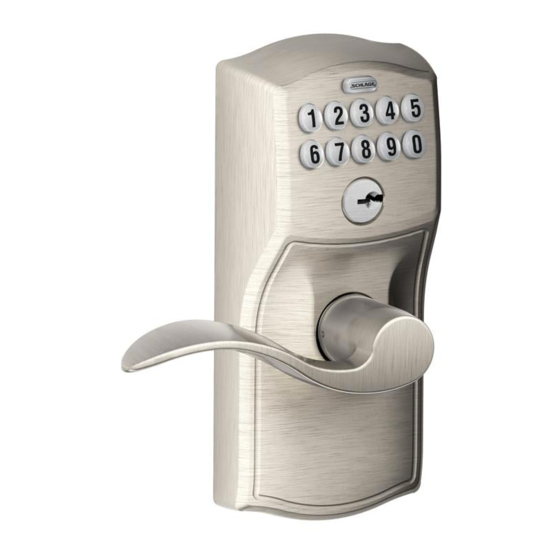
Home Keypad Lock
Installation Instructions
Model FE599
Need help?
(888) 805-9837
(U.S.A./Canada)
2b. Install strike onto door jamb.
2c. If Necessary, change latch faceplate.
Check edge of door to determine the type of faceplate required.
Actual Size (2)
3b. Install exterior keypad.
Bar should slide smoothly through hole in latch. If not, check door dimensions.
exterior
Bar
4b. Slide baseplate onto door over hands-free post.
Hands-free post should lock plate against door surface.
If hands-free post does not lock plate onto door, see step 3c for adjustment.
5b. Install interior lever.
If the lever does not snap into place easily, you may have to tap the
lever with a hammer using a piece of wood to cushion it. Be careful not
to damage the finish of the lever.
6b. Test outside entry.
1. Find User Code A on the yellow sticker.
2. Enter User Code A (four digits) into the keypad.
3. Rotate and then release lever.
Tools Needed
• Phillips screwdriver
• Tape Measure
• Pencil
optional
Keypad
• Flathead Screwdriver
• Wood Block
• Hammer
do not use a power
drill for installation
Key
No change necessary.
OR
IMPoRTANT
Cable must slide
under latch.
4c. Connect the cable.
Snap the connectors together. Route wires so they will not be pinched.
hands-free post
5c. If needed, switch levers.
Correct
No change necessary
See step 5c to verify
that the lever is handed
correctly to match your
door.
Did latch retract and then extend?
Yes. Lock is installed correctly.
No. Latch retracted but did not extend
(latch bound). Check step 3b.
No. Nothing happened. Check steps 4c
and 4d.
Contents
Interior
Cover
Interior
Baseplate
Latch
Strike
Latch/Strike
Screws (4)
2d. Install Latch.
Latch must be flipped so that bevel faces toward door jamb.
OR
3c. Adjust hands-free post.
The hands-free post is the threaded stud
hold keypad
on back of lock. It's purpose (in step 4) is to
against door
attach the lock and baseplate together so that
the lock will hold itself on the door. Hands-
free post may need to be adjusted with a
screwdriver to the dimensions shown.
hands-free post
1
Incorrect
To Change Lever Handing
3
CAUTIoN
If Lock Removal is Required
Hands free post must be disengaged to
prevent damage to lock.
Lever
Cover Screws
Pin Wrench
(2)
Alternate
Faceplate
AA Batteries (4)
not included
Bevel
Jamb
Z\," - Z\v"
(3mm - 6mm)
Adjust with
screwdriver
so screw
extends
beyond door
edge.
4d. Install batteries and battery cover.
2
4
FCC STATeMeNT
This device complies with part 15 of the FCC rules.
Operation is subject to the following two conditions:
(1) This device may not cause harmful interference,
and (2) this device must accept any interference
received, including interference that may cause
undesired operation.
Changes or modifications to this equipment not
expressly approved by Schlage could void the
user's authority to operate the equipment.
FCC ID: P2GFE599
IC: 7654A-FE599
© Allegion 2014
Printed in U.S.A.
P515-862 07/14-e
Publicidad

Manuales relacionados para Schlage FE599


Resumen de contenidos para Schlage FE599
- Página 1 Changes or modifications to this equipment not To Unlock (from inside): 1. Find User Code A on the yellow sticker. expressly approved by Schlage could void the Press the Unlock button. Press the Lock button. 2. Enter User Code A (four digits) into the keypad.
- Página 2 Los cambios o modificaciones hechas a este equipo sin contar con Para abrir (desde el interior): Le pivot doit être libéré manuellement pour prévenir les extendió? la autorización expresa de Schlage podrían anular la autoridad Presione el botón. amarillo. Presione el botón.
- Página 3 Release Date White Paper D. Rollison M. Roberts 054442 07-11-14 Notes Title 1. printed two sides Fe599 IS 2. printed black Creation Date Number Revision 3. tolerance ± .13 06-20-2008 4. printed in country may vary P515-862 5. drawings not to scale...