Tabla de contenido
Publicidad
Idiomas disponibles
Idiomas disponibles
Enlaces rápidos
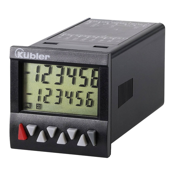
CODIX 924-4: mit 4 Vorwahlen (Relais)
Ausführungen
LCD positiv
LCD positiv, grün hinterleuchtet
LCD negativ, rot hinterleuchtet
LCD negativ, rot-grün hinterleuchtet
With four presets (relays)
Models
LCD positive
LCD positive, green backlighting
LCD negative, red backlighting
LCD negative, red-green backlighting
avec quatre présélections (relais)
Exécutions
LCD positif
LCD positif, rétroéclairage vert
LCD négatif, rétroéclairage rouge
LCD négatif, rétroéclairage rouge-vert
con quattro preselezioni (relè)
Esecuzioni
LCD positivo
LCD positivo, retroilluminazione verde
LCD negativo, retroilluminazione rossa
LCD negativo, retroilluminazione verde-rossa
con cuatro preselecciones (relés)
Modelos
LCD positivo
LCD positivo, retroiluminación verde
LCD negativo, retroiluminación roja
LCD negativo, retroiluminación verde-roja
Publicidad
Tabla de contenido

Manuales relacionados para Kübler CODIX 924-4


Resumen de contenidos para Kübler CODIX 924-4
- Página 1 CODIX 924-4: mit 4 Vorwahlen (Relais) Ausführungen LCD positiv LCD positiv, grün hinterleuchtet LCD negativ, rot hinterleuchtet LCD negativ, rot-grün hinterleuchtet With four presets (relays) Models LCD positive LCD positive, green backlighting LCD negative, red backlighting LCD negative, red-green backlighting avec quatre présélections (relais)
- Página 2 Vorwort Sicherheits- und Warnhinweise Bestimmungsgemäßer Gebrauch Schalttafeleinbau Elektrische Installation Beschreibung Anzeige/Bedienelemente Eingänge INP A, INP B RESET GATE LOC.INP Ausgänge Ausgang 1 und Ausgang 3 Ausgang 2 und Ausgang 4 Aktive Ausgänge Programmierung Einstieg in die Programmierung Anwahl der Hauptmenues Einstieg in ein Untermenue Anwahl der Menuepunkte Einstellung der Menuepunkte...
- Página 3 10.12 Mechanische Daten 10.13 Anschlüsse 11 Lieferumfang 12 Bestellschlüssel 13 Frequenzen (typ.) 13.1 Impulszähler 13.2 Frequenzzähler 14 Eingangsarten Impulszählung 15 Eingangsarten Zeitmessung 16 Eingangsarten Frequenzzähler 17 Ausgangsoperationen 18 Maßbilder www.kuebler.com Seite 3...
- Página 4 Montieren Sie das Gerät entfernt Lesen Sie vor der Montage und der von Wärmequellen und vermeiden Inbetriebnahme diese Bedienungs- Sie direkten Kontakt mit ätzenden anleitung durch. Beachten Sie zu Ihrer Flüssigkeiten, heißem Dampf oder VORSICHT eigenen Sicherheit und der ähnlichen. Betriebssicherheit alle Warnungen und Hinweise.
- Página 5 T1-6 Dekadentaste T1 … T6 6-stellige Multifunktions- LCD-Anzeige Prog/Mode-Taste Gut ablesbare 2-zeilige LCD-Anzeige mit Symbolen Reset-Taste für die angezeigte Vorwahl und den Zustand der Ausgänge Aktueller Zählwert / Hauptzähler Gleichzeitige Anzeige des Istwert und der Vorwahlwert/ Gesamtsumme/ Batchzähler Vorwahlen bzw. den Nebenzählern Ausführung ohne/mit hintergrundbeleuchtetem 10 Laufanzeige beim Zeitzähler Display...
- Página 6 Mit der Prog/Mode-Taste wird innerhalb des Untermenues ein Menuepunkt angewählt. Relais mit potentialfreiem Schließkontakt Mit der Taste T2 werden die Relais mit potentialfreiem Wechselkontakt einzelnen Einstellungen der Menuepunkte angewählt Ein aktiver Ausgang wird auf dem Display mit Bei Einstellungen von oder angezeigt.
-
Página 7: Voreingestellte Parametersätze
Õ In der Anzeige wird für P.SEt 1 P.SEt 2 P.SET 3 2 s der Text SAVE FActor 01.0000 01.0000 01.0000 angezeigt diViSo 01.0000 01.0000 01.0000 0.00 SEtPt 000000 000000 0000.00 CoLor red.Grn red.Grn red.Grn 7.8.1 Voreingestellte Parametersätze rESmd Man.EL Man.EL Man.EL Pr.Out 1... - Página 8 7.8.4 Impulszähler Phasendiskriminator mit Impulsvervierfachung INP A: Zähleingang 0° 7.8.4.1 Untermenue für die Signal- und INP B: Zähleingang 90° Steuereingänge Jede Flanke von INP A und INP Menue zum Programmieren der B wird gezählt. Signal- und Steuereingänge Ratiomessung [A / B] Inp A: Zähleingang A Inp B: Zähleingang B Eingangspolarität...
- Página 9 Subtrahierende Zählung Elektrischer Reset setzt nur Ausgang 1, 3 und 4 aktiv bei Hauptzähler auf Null Zählerstand < Vorwahl 1, 3 und 4 Ausgang 2 aktiv bei Zählerstand 7.8.4.3 Untermenue zur Konfiguration < 0 Untermenue zur Anpassung der Reset auf Vorwahl 2 Eingangsimpulse und Anzeige Addierende Zählung mit automatischem Reset...
- Página 10 nur elektrische Rückstellung Summenmessung [A + B] möglich (Reset-Eingang) Inp A: Frequenzeingang A Inp B: Frequenzeingang B Frequenzmessung mit nur manuelle Rückstellung Richtungserkennung [Quad] möglich (rote Taste) Inp A: Frequenzeingang 0° Inp B: Frequenzeingang 90° Ratiomessung [A / B] 7.8.4.5 Vorwahl 1 Inp A: Frequenzeingang A weiter bei 7.8.6.5 Inp B: Frequenzeingang B...
- Página 11 Divisionsfaktor 7.8.5.3 Vorwahl 1 Divisionsfaktor von 01.0000 bis weiter bei 7.8.6.5 99.9999 einstellbar. 7.8.5.4 Vorwahl 2 Die Einstellung <01.0000 wird nicht übernommen weiter bei 7.8.6.6 Anzeigemode 7.8.5.5 Vorwahl 3 und 4 Umrechnung und Anzeige der weiter bei 7.8.6.7 Frequenz / Geschwindigkeit in 7.8.6 Zeitzähler Umrechnung und Anzeige der 7.8.6.1 Untermenue für die Signal- und...
- Página 12 Ausgangsoperationen) 7.8.6.2 Untermenue für zurückgesetzt und wieder Ausgangsoperationen gestartet. Bei addierenden Festlegung der Ausgangsoperationen wird bei Ausgangsoperation Erreichen der Vorwahl 2 , bei subtrahierenden Ausgangsoperationen bei Addierende Zählung Erreichen von Null die Ausgänge aktiv bei Zählerstand Zeitmessung gestoppt. Ein > Vorwahl RESET während der Zeitzählung Reset auf Null stoppt diese ebenfalls.
- Página 13 bei Hauptzähler = Vorwahl 2 Anzeigefarbe Automatischer Reset auf Null bei obere Zeile Hauptzähler = Vorwahl 2 untere Zeile grün Ausgänge 3 aktiv bei Hauptzähler > Vorwahl 3 Gesamtsummenzähler zählt alle 7.8.6.4 Untermenue für Rücksetzmode Zählimpulse vom Hauptzähler Einstellung des Rücksetzmodes Ausgang 1 bzw.
- Página 14 add. Ausgangsoperationen: add. Ausgangsoperationen: Wischsignal am Ausgang1, wird Dauersignal am Ausgang 2, wird bei Zählerstand > Vorwahl 1 bei Zählerstand >= Vorwahl 2 aktiv. (Aktivierung nur in positiver aktiv Richtung) sub. Ausgangsoperationen: sub. Ausgangsoperationen: Dauersignal am Ausgang 2, wird Wischsignal am Ausgang 1, wird bei Zählerstand <...
-
Página 15: Einstellung Über Dekadentaster
Zählerstand < Null passiv und Vorwahl 3 [4] aktiv anschließend bei positiver sub. Ausgangsoperationen: Richtung und Zählerstand > Null Wischsignal am Ausgang 3 [4], passiv wird bei negativer Richtung und Zählerstand < Vorwahl 3 [4] aktiv Dauer des Wischsignals von und anschließend bei positiver Ausgang 2, einstellbar von 00.01 Richtung und Zählerstand >... -
Página 16: Einstellung Mit Teach-Funktion
Prog/Mode-Taste betätigen um den Wert zu bestätigen und zu speichern Õ Anzeige schaltet in den Editiermode der nächsten Vorwahl. Ca. 3 s nach dem letzten Betätigen der Dekadentasten oder durch Betätigen der Reset- Taste wird der neue Vorwahlwert übernommen und in den Betriebsmode zurück geschaltet. - Página 17 Schaltpegel bei AC-Versorgung: HTL-Pegel Low: 0 ... 4 VDC High: 12 ... 30 VDC 5V-Pegel Low: 0 ... 2VDC Anzeige LCD positiv oder negativ, High: 3,5 … 30 VDC hinterleuchtet Schaltpegel bei DC-Versorgung: 2 x 6-stellig HTL-Pegel Low: 0 ... 0,2 x UB Ziffernhöhe obere Zeile 9 mm...
- Página 18 Signal- und Steuereingänge: Steckbare Schraubklemme, 8-polig, RM 3,81 AC-Versorgung: 90 ... 260 V AC / max. 8 VA Aderquerschnitt, max. 1,5 mm² 50/ 60 Hz Absicherung extern: T 0,1 A DC-Versorgung: 10 ... 30 V DC/ max. 1,5 W Vorwahlzähler mit Verpolschutz Spannbügel Absicherung extern T 0,2 A...
- Página 19 HTL-Pegel AC-Versorgung typ.Low 2,5 V typ. High 22 V DC-Versorgung 12V typ.Low HTL-Pegel typ. High 10 V AC-Versorgung typ.Low 2,5 V DC-Versorgung 24V typ.Low 2,5 V typ. High 22 V typ. High 22 V DC-Versorgung 12V typ.Low typ. High 10 V 5V-Pegel DC-Versorgung 24V typ.Low...
- Página 20 Funktion Diagramm PnP: Zählung bei steigender Flanke nPn: Zählung bei fallender Hinweis: Wenn GATE-Eingang aktiv keine Zählung Flanke P = Preset (Vorwahlwert) Cnt.Dir Inp A: Zähleingang Inp B: Zählrichtung Add: Anzeige 0 --> Vorwahl Sub: Anzeige Vorwahl -> 0 Inp A: Zähleingang add Up.Dn Inp B: Zähleingang sub Add: Anzeige 0 -->...
- Página 21 Funktion Diagramm PnP: Zählung bei steigender Flanke nPn: Zählung bei fallender Hinweis: Wenn GATE-Eingang aktiv keine Zählung Flanke Quad 4 A 90° B Inp A: Zähleingang Zählung bei steigender und fallender Flanke Inp B: Zähleingang Zählung bei steigender und fallender Flanke, Umkehr der Richtung Add: Anzeige 0 -->...
- Página 22 Funktion Diagramm PnP: Zählung bei steigender Flanke nPn: Zählung bei fallender Flanke InA.InB Inp A: Start Inp B: Stop Add: Anzeige 0 --> Vorwahl Sub: Anzeige Vorwahl -> 0 InB.InB Inp A: ohne Funktion Inp B: Start/Stop Add: Anzeige 0 --> Vorwahl Sub: Anzeige Vorwahl ->...
- Página 23 Funktion Diagramm PnP: Zählung bei steigender Flanke nPn: Zählung bei fallender Flanke Inp A: Frequenzeingang Inp B: ohne Funktion AsubB Inp A: Frequenzeingang 1 Inp B: Frequenzeingang 2 Formel: A - B AaddB Inp A: Frequenzeingang 1 Inp B: Frequenzeingang 2 Formel: A + B Quad...
- Página 24 Mode Diagramm Mode Diagramm Nur im Mode Zusätzlich im Mode AddAr SubAr AddBat AddTot www.kuebler.com Seite 24...
- Página 25 Schalttafelausschnitt www.kuebler.com Seite 25...
- Página 28 Preface Safety Instructions and Warnings Use according to the intended purpose Mounting in a control panel Electrical Installation Description Display/Operating elements Inputs INP A, INP B RESET GATE LOCK INPUT Outputs Output 1 and output 3 Output 2 and output 4 Active Outputs Programming Entering the programming...
- Página 29 10.12 Mechanical Data 10.13 Connections 11 Scope of Delivery 12 Ordering codes 13 Frequencies (typical) 13.1 Pulse counter 13.2 Frequency meter 14 Input modes: Pulse counting 15 Input modes: Timing 16 Input modes: Frequency meter 17 Output operations 18 Dimensional Drawings www.kuebler.com Page 3...
- Página 30 Mount the device away from heat Please read this instruction manual sources and avoid direct contact carefully before installation and start-up. with corrosive liquids, hot steam or Please observe all warnings and similar. CAUTION advice, both for your own safety and for general plant safety.
- Página 31 T1-6 Decade key T1 … T6 6-digit multifunction LCD display Prog/Mode key Easy-to-read 2-line LCD-display with annunciators Reset key for both the displayed preset and the status of the outputs Current count value / main counter Simultaneous display of the actual value and of the Preset value/ Total count/ Batch counter presets or auxiliary counters Versions with/without backlit display...
- Página 32 The Prog/Mode key is used to select a menu item within the sub-menu Relay with potential-free make (NO) contact. The T2 key is used to select the Relay with potential-free changeover contact. individual settings for the menu items An active output will be shown on the display as When setting count values, each decade has a key assigned to it.
-
Página 33: Default Parameters
Õ The text SAVE is P.SEt 1 P.SEt 2 P.SET 3 displayed for 2 s FActor 01.0000 01.0000 01.0000 diViSo 01.0000 01.0000 01.0000 0.00 SEtPt 000000 000000 0000.00 7.8.1 Default parameters CoLor red.Grn red.Grn red.Grn rESmd Man.EL Man.EL Man.EL Note: Three default parameter Pr.Out 1 sets have been permanently t.Out 1... -
Página 34: Pulse Counter
7.8.4 Pulse Counter Quadrature x4 INP A: count input 0° INP B: count input 90° 7.8.4.1 Submenu for the Signal and Each pulse edge of INP A and Control inputs INP B will be counted. Menu for programming the signal Ratio measurement [A / B] and control inputs Inp A: count input A... - Página 35 Count mode SUBTRACT resp. 4 Outputs 1, 3 and 4 active when Manual Reset sets both counters count status < preset values 1, 3 to zero and 4 Electrical reset only sets the Output 2 active when main counter to zero count status <...
-
Página 36: Tacho/Frequency Meter
No reset possible (red key and Differential measurement reset input inhibited) [A – B] Inp A: Frequency input A Inp B: Frequency input B Only electrical reset possible Total measurement [A + B] (reset input) Inp A: Frequency input A Inp B: Frequency input B Only manual reset possible (red key) - Página 37 Multiplication factor Display colour Upper line Multiplication factor can be Lower line green programmed from 00.0001 to 99.9999. The setting 00.0000 will not be accepted 7.8.5.3 Preset 1 Division factor See below 7.8.6.5 Division factor can be programmed from 01.0000 to 7.8.5.4 Preset 2 99.9999.
- Página 38 The timer is reset by means of a 7.8.6.2 Submenu for the output operations RESET (to zero when adding, to Submenu for determining the preset 2 when subtracting) and operation of the outputs then starts timing again. Timing is stopped with adding operations when preset 2 is Count mode ADD reached.
- Página 39 when main counter = preset value 2 Display colour Automatic reset to zero when upper line main counter = preset value 2 lower line green Output 3 active when main counter > preset value 3 Total counter counts all the count 7.8.6.4 Submenu for reset mode pulses from the main counter Setting the reset mode...
- Página 40 ADD mode output operations: ADD mode output operations: timed signal at Output 1, permanent signal at Output 2, becomes active when count > becomes active when count > Preset 1. (Activation only in Preset 2 positive direction) SUB mode output operations: SUB mode output operations: permanent signal at Output 2, timed output at Output 1,...
-
Página 41: Setting Via Decade Keys
becomes passive with negative when count < Preset 3 [4] direction and when count < zero SUB mode output operations: and subsequently with positive timed signal at Output 3 [4], direction and when count > zero becomes active with negative direction and when count <... -
Página 42: Setting With Teach-In Function
Press the Prog/Mode key to confirm the value and save it Õ Display switches to the editor mode of the next preset Approx. 3 s after the last press of the decade keys or by pressing the Reset key the new preset value will be accepted and the counter will switch back to operating mode. - Página 43 Switching level with AC supply: HTL level Low: 0 ... 4 VDC High: 12 ... 30 VDC 5V level Low: 0 ... 2VDC Display LCD positive or negative, High: 3,5 … 30 VDC backlit Switching level with DC supply: 2 x 6-digit HTL level Low: 0 ...
- Página 44 AC supply: 90 ... 260 V AC / max. 8 VA 50/ 60 Hz Preset counter ext. fuse protection: T 0.1 A Mounting clip DC supply: 10 ... 30 V DC/ max. 1.5 W Instruction manual reverse polarity protection ext. fuse protection T 0.2 A 6.924.X10X.XXC 24 V DC ±15%, 80 mA AC supply:...
- Página 45 HTL level AC supply typ. Low 2,5 V typ. High 22 V DC supply 12V typ. Low HTL level typ. High 10 V AC supply typ. Low 2,5 V DC supply 24V typ. Low 2,5 V typ. High 22 V typ.
- Página 46 Function Diagram PNP: Count on rising edge NPN: Count on falling edge Note: No counting when GATE input is active P = Preset Cnt.Dir Inp A: Count input Inp B: Count direction Add: Display 0 --> Preset Sub: Display Preset -> 0 Inp A: Count input add Up.Dn Inp B: Count input sub...
- Página 47 Function Diagram PNP: Count on rising edge NPN: Count on falling edge Note: No counting when GATE input is active Quad 4 A 90° B Inp A: Count input Count on rising and on falling edges Inp B: Count input Count on rising and on falling edges, Reverse direction...
- Página 48 Function Diagram PNP: Count on rising edge NPN: Count on falling edge InA.InB Inp A: Start Inp B: Stop Add: Display 0 --> Preset Sub: Display Preset -> 0 InB.InB Inp A: no function Inp B: Start/Stop Add: Display 0 --> Preset Sub: Display Preset ->...
- Página 49 Function Diagram PNP: Count on rising edge NPN: Count on falling edge Inp A: Frequency input Inp B: no function AsubB Inp A: Frequency input 1 Inp B: Frequency input 2 Formula: A - B AaddB Inp A: Frequency input 1 Inp B: Frequency input 2 Formula: A + B...
- Página 50 Mode Diagram Mode Diagram Only in the mode Additionally in the mode AddAr SubAr AddBat AddTot www.kuebler.com Seite 24...
- Página 51 Panel cut-out www.kuebler.com Seite 25...
- Página 54 Introduction Instructions de sécurité et avertissements Utilisation conforme Montage encastré Installation électrique Description Affichage/Organes de commande Entrées INP A, INP B RESET GATE LOC.INP Sorties Sortie 1 et sortie 3 Sortie 2 et sortie 4 Sorties actives Programmation Appel du mode Programmation Appel des menus principaux Passage dans un sous-menu Appel des points du menu...
- Página 55 10.12 Caractéristiques mécaniques 10.13 Raccordements 11 Etendue de la livraison 12 Référence de commande 13 Fréquences (typiques) 13.1 Compteur d’impulsions 13.2 Fréquencemètre 14 Types d’entrée - Comptage d’impulsions 15 Types d’entrée - Mesure de temps 16 Types d’entrée - Fréquencemètre 17 Opérations de sortie 18 Dimensions www.kuebler.com...
- Página 56 Montez l’appareil loin de toute Lisez attentivement ces instructions source de chaleur et évitez tout d’utilisation avant le montage et la mise contact direct avec des liquides en service. Pour votre propre sécurité, corrosifs, de la vapeur chaude ou PRUDENCE ainsi que pour la sécurité...
- Página 57 Les conducteurs et les isolations de ceux-ci doivent correspondre aux plages de température et de tension prévues. Afficheur LCD multifonctions à 6 décades Affichage LCD à 2 lignes clairement lisible avec symboles pour la présélection affichée et l’état des sorties Affichage simultané...
- Página 58 La touche T2 permet de choisir Entrée de porte statique : fonction suivant le mode de continuer la programmation opératoire. Compteur d’impulsions : pas de comptage si active Õ L’appareil affiche la Fréquencemètre : pas de comptage si active demande de Compteur horaire : pas de mesure de temps si confirmation...
-
Página 59: Jeux De Paramètres Prédéfinis
Õ L’appareil affiche la Prédéfinition demande de Jeu de paramètres 2 confirmation Prédéfinition Si cette question est validée en Jeu de paramètres 3 pressant la touche Prog/Mode, le menu de programmation recommence du début. Les Réglages libres de l’utilisateur dernières valeurs réglées sont sauvegardées. -
Página 60: Compteur D'impulsions
Menu de programmation Discriminateur de phase Compteur de temps/Compteur INP A : Entrée de comptage 0° d’heures de fonctionnement INP B : Entrée de comptage 90° (7.8.6) Menu de programmation Discriminateur de phase avec Tachymètre/Fréquencemètre doublement des impulsions INP A : Entrée de comptage 0° (7.8.5) INP B : Entrée de comptage 90°... - Página 61 7.8.4.2 Sous-menu des opérations de sortie Comptage additionnant avec repositionnement automatique Sous-menu pour la détermination et totalisateur de l’opération de sortie Sortie 2 (signal fugitif) active lorsque compteur principal = présélection 2 Comptage additionnant Repositionnement automatique à Sorties actives lorsque zéro lorsque compteur principal = compteur >...
- Página 62 Couleur de l’affichage (appareil 6.924.x103.xxC) Polarité d’entrée Couleur de l’affichage PnP : commutation positive ligne supérieure rouge commune pour toutes les entrées ligne inférieure rouge nPn : commutation à 0V commune pour toutes les Couleur de l’affichage entrées ligne supérieure rouge ligne inférieure vert Filtre pour les entrées de signal Inp A et Inp B...
-
Página 63: Compteur Horaire
La fréquence courante est prise Formation de la moyenne glissante en compte comme nouvelle Formation de la moyenne valeur pour la présélection glissante sélectionnée lors de l’activation AVG 2 sur 2 mesures de l’entrée MPI. Voir aussi 7.9 AVG 5 sur 5 mesures AVG 10 sur 10 mesures... - Página 64 Polarité d’entrée Entrée utilisateur PnP : commutation positive L’affichage est figé lors de commune pour toutes les l’activation de l’entrée MPI et entrées reste figé jusqu’à la désactivation de l’entrée MPI. Le compteur horaire à nPn : commutation à 0V présélection continue de compter commune pour toutes les en interne.
- Página 65 zéro lorsque compteur = 7.8.6.3 Sous-menu de configuration présélection 2 Menu de paramètres pour Repositionnement à zéro l’adaptation des plages de temps et de l’affichage Comptage soustrayant avec repositionnement automatique Sorties 1, 3 et 4 actives lorsque Unité de temps compteur <...
- Página 66 Aucun repositionnement (touche Opérations de sortie additionn. : rouge et entrée Reset bloquées) Signal fugitif à la sortie 1, activé dans la direction positive et lorsque compteur > présélection 1, puis activé dans la direction Repositionnement électrique négative et lorsque compteur < uniquement (entrée Reset) présélection 1 Opérations de sortie soustr.
- Página 67 Opérations de sortie soustr. : Opérations de sortie additionn. : Signal permanent à la sortie 2, Signal permanent à la sortie 3 activé lorsque compteur < zéro [4], activé lorsque compteur > (Activation uniquement dans la présélection 3 [4] direction négative) Opérations de sortie soustr.
-
Página 68: Réglage À L'aide De La Fonction D'apprentissage (Teach)
Õ Opérations de sortie additionn. : L’affichage passe dans le mode d’édition Signal fugitif à la sortie 3 [4], de la présélection suivante. désactivé dans la direction positive et lorsque compteur > La nouvelle présélection est prise présélection 3 [4], puis désactivé en compte environ 3 s après la dans la direction négative et dernière action sur les touches... - Página 69 N° Désignation Fonction 16 Contact de relais N.C.4 Sortie 4 Err 1 Valeur de prépositionnement hors de la plage autorisée 17 Contact de relais C.4 18 Contact de relais N.O.4 19 Contact de relais N.O.3 Sortie 3 20 Contact de relais C.3 Affichage LCD positif ou négatif, rétroéclairé...
- Página 70 Durée de vie mécanique (commutations) 5x10 Nombre de commutations - 0,5A/125 VAC 1x10 Nombre de commutations - 1 A/30 V DC 1x10 Polarité : programmable, NPN/PNP commune à toutes les entrées Sortie 4 Résistance d’entrée 5 k Relais avec contact inverseur Forme des impulsions quelconque Tension de commutation Niveau de commutation en alimentation AC :...
- Página 71 Conception selon : EN61010 Partie 1 6.924.X10X.XXC Classe de protection : Classe de protection 2 Domaine d’utilisation : Degré de salissure 2 2 sorties par relais supplémentaires Niveau d’entrée Boîtier : Boîtier à encastrer 0 = Niveau standard (HTL) selon DIN 43 700, RAL 7021 A = Niveau fixe* Dimensions: 48 x 48 x 91 mm...
- Página 72 Niveau HTL Alimentation AC typ. Bas 2,5 V typ. Haut 22 V Alimentation DC 12V typ. Bas Niveau HTL typ. Haut 10 V Alimentation AC typ. Bas 2,5 V Alimentation DC 24V typ. Bas 2,5 V typ. Haut 22 V typ.
- Página 73 Fonction Diagramme PnP : comptage sur le flanc montant nPn : comptage sur le flanc Nota : pas de comptage lorsque l’entrée GATE est active descendant P = Preset (présélections) Cnt.Dir Inp A : Entrée de comptage Inp B : Sens de comptage Add.
- Página 74 Fonction Diagramme PnP : comptage sur le flanc montant nPn : comptage sur le flanc Nota : pas de comptage lorsque l’entrée GATE est active descendant Quad 4 A 90° B Inp A : Entrée de comptage Comptage sur flanc montant et sur flanc descendant Inp B : Entrée de comptage Comptage sur flanc montant...
- Página 75 Fonction Diagramme PnP : comptage sur le flanc montant nPn : comptage sur le flanc descendant InA.InB Inp A : Marche Inp B : Arrêt Add : Affichage 0 -> Présél. Sub : Affichage Présél -> 0 InB.InB Inp A : Sans fonction Inp B : Marche/Arrêt Add : Affichage 0 ->...
- Página 76 Fonction Diagramme PnP : comptage sur le flanc montant nPn : comptage sur le flanc descendant Inp A : Entrée de fréquence Inp B : Sans fonction AsubB Inp A : Entrée de fréquence Inp B : Entrée de fréquence Formule : A - B AaddB...
- Página 77 Mode Diagramme Mode Diagramme Uniquement en mode en plus en mode AddAr SubAr AddBat AddTot www.kuebler.com Page 25...
- Página 78 Découpe d’encastrement www.kuebler.com Page 26...
- Página 80 Introduzione Istruzioni di sicurezza e avvertenze Utilizzo conforme Montaggio incassato Installazione elettrica Descrizione Visualizzazione/Organi di comando Ingressi INP A, INP B RESET GATE LOC.INP Uscite Uscita 1 ed uscita 3 Uscita 2 ed uscita 4 Uscite attive Programmazione Richiamo della modalità Programmazione Richiamo dei menu principali Passaggio ad un sottomenu Richiamo dei punti del menu...
- Página 81 10.12 Caratteristiche meccaniche 10.13 Collegamenti 11 La consegna include 12 Codificazione per l’ordinazione 13 Frequenze (specifiche) 13.1 Contatore di impulsi 13.2 Frequenzimetro 14 Tipi d’ingresso – Conteggio di impulsi 15 Tipi d’ingresso – Misura del tempo 16 Tipi d’ingresso - Frequenzimetro 17 Operazioni di uscite 18 Dimensioni www.kuebler.com...
- Página 82 Montare l’apparecchio lontano da Prima di procedere al montaggio ed alla ogni fonte di calore ed evitare ogni messa in funzione, leggere contatto diretto con liquidi corrosivi, attentamente le presenti istruzioni vapore caldo o sostanze simili. PRECAUZIONE d’uso. Per salvaguardare la vostra sicurezza e la sicurezza di funzionamento, rispettare tutte le Istruzioni per il montaggio...
- Página 83 I conduttori ed i loro isolamenti devono soddisfare i campi di temperatura e di tensione previsti. Display LCD multifunzione a 6 decadi Visualizzazione LCD a 2 righe ben visibile, con simboli per la preselezione visualizzata e lo stato delle uscite Visualizzazione contemporanea del valore reale e delle preselezioni o dei contatori ausiliari Esecuzione con/senza retroilluminazione della...
- Página 84 Frequenzimetro: senza funzione Il tasto Prog/Modo consente di Contatore orario: ingresso di RESET uscire dalla programmazione Il tasto T2 consente di continuare Ingresso di porta statico: funzione secondo la la programmazione modalità operativa. Contatore di impulsi: nessun conteggio mentre attivo Õ...
-
Página 85: Gruppi Di Parametri Predefiniti
Premere il tasto Reset Predefinizione Gruppo di parametri 2 Õ Il display visualizza la Predefinizione richiesta di conferma Gruppo di parametri 3 Se questa richiesta è confermata dalla pressione del tasto Regolazioni libere dell’operatore Prog/Modo, il menu di programmazione ricomincia dall’inizio. -
Página 86: Contatore Di Impulsi
Menu di programmazione Discriminatore di fase Contatore di tempo/Contatore INP A: Ingresso di conteggio 0° d’ore di funzionamento (7.8.6) INP B: Ingresso di conteggio 90° Menu di programmazione Discriminatore di fase con Tachimetro/Frequenzimetro raddoppiamento degli impulsi INP A: Ingresso di conteggio 0° (7.8.5) INP B: Ingresso di conteggio 90°... - Página 87 delle preselezioni e la contatore di partite è > alla programmazione sono proscritte. preselezione 1 risp. 4 Il Reset manuale ripristina i due contatori a zero 7.8.4.2 Sottomenu delle operazioni di uscita Il Reset elettrico ripristina solo il Sottomenu per la determinazione contatore principale a zero dell’operazione di uscita Conteggio sommante con...
- Página 88 Preimpostazione regolabile tra -999999 e 999999 Polarità d’ingresso Qualora un punto decimale sia PnP: commutazione positiva stato programmato prima, esso comune per tutti gli ingressi viene visualizzato Colore del display (apparecchio 6.924.x103.xxC) nPn: commutazione a 0V Colore del display comune per tutti gli ingressi linea superiore rosso linea inferiore...
-
Página 89: Contatore Orario
All’attivazione dell’ingresso MPI, la frequenza corrente viene Formazione della media scorrevole presa in considerazione come Formazione della media nuovo valore per la preselezione scorrevole selezionata. AVG 2 su 2 misure Vedi anche 7.9 AVG 5 su 5 misure AVG 10 su 10 misure AVG 20 su 20 misure... - Página 90 All’attivazione dell’ingresso MPI, la visualizzazione è congelata e nPn: commutazione a 0V lo rimane fino alla disattivazione comune per tutti gli ingressi dell’ingresso MPI. Il contatore a preselezione procede al conteggio Filtro per gli ingressi di segnale Inp A e Inp B internamente.
- Página 91 quando il contatore è = alla 7.8.6.3 Sottomenu di configurazione preselezione 2 Menu di parametri per Ripristino a zero l’adattamento degli intervalli di tempo e della visualizzazione Conteggio sottraente con ripristino automatico Uscita 1, 3 e 4 attiva quando il Unità...
- Página 92 Nessun ripristino (tasto rosso e Operazioni di uscita sommanti: ingresso Reset bloccati) segnale temporaneo all’uscita 1 attivato nella direzione positiva e quando il contatore è > alla preselezione 1, poi attivato nella Ripristino elettrico solo (ingresso direzione negativa e quando il Reset) contatore è...
- Página 93 Operazioni di uscita sommanti: 7.8.6.7 Sottomenu della preselezione 3 e 4 segnale temporaneo all’uscita 2 Solo la preselezione 3 è rappresentata qui di sotto. attivato quando il contatore è > alla preselezione 2 (attivazione Sottomenu per la preselezione 3 solo nella direzione positiva). Operazioni di uscita sottraenti: segnale temporaneo all’uscita 2 attivato quando il contatore è...
-
Página 94: Regolazione Tramite La Funzione D'apprendimento (Teach)
negativa e quando il contatore è Regolare la preselezione con < alla preselezione 3 [4], poi l’ausilio dei tasti delle decadi attivato nella direzione positiva e quando il contatore è > alla preselezione 3 [4] Premere il tasto Prog/Modo per confermare e memorizzare la Operazioni di uscita sommanti: preselezione... - Página 95 di SEtPt per le operazioni di uscita N. Designazione Funzione sottraenti. DC: GND (0 VDC) tensione 16 Contatto di relè N.C.4 17 Contatto di relè C.4 Uscita 4 Err 1 Valore di preimpostazione al di fuori del 18 Contatto di relè N.O.4 campo ammesso 19 Contatto di relè...
- Página 96 Errore di misura < 50 ppm Potenza di commutazione max. 62,5 VA/ 30 W Tempo di risposta delle uscite: Durata di vita meccanica (commutazioni) 5x10 Relè < 14 ms Numero di commutazioni a 0,5A/125 VAC 1x10 Numero di commutazioni a 1 A/30 V DC 1x10 Uscita 4 Relè...
- Página 97 Scatola: scatola ad incastro secondo DIN 43 700, RAL 7021 Dimensioni: 48 x 48 x 91 mm +0,6 +0,6 Apertura d’incastro: 45 x 45 6.924.X10X.XXC Prof. di montaggio circa 107 mm morsetti inclusi 2 uscite con relè Peso: circa 125 g supplementari Indice di protezione: IP 65 (frontale) Livello d’ingresso...
- Página 98 Livello HTL Alimentazione AC spec. Basso 2,5 V spec. Alto 22 V Alimentazione DC 12V spec. Basso Livello HTL spec. Alto 10 V Alimentazione AC spec. Basso 2,5 V Alimentazione DC 24V spec. Basso 2,5 V spec. Alto 22 V spec.
- Página 99 Funzione Diagramma PnP: conteggio sul fronte salente Nota: nessun conteggio quando l’ingresso GATE è attivo. nPn: conteggio sul fronte discendente P = Preset (preselezione) Cnt.Dir Inp A: Ingresso di conteggio Inp B: Senso di conteggio Add: Visualiz. 0 -> Preselez. Sub.: Visualiz.
- Página 100 Funzione Diagramma PnP: conteggio sul fronte salente Nota: nessun conteggio quando l’ingresso GATE è attivo. nPn: conteggio sul fronte discendente Quad 4 A 90° B Inp A: Ingresso di conteggio Conteggio su fronte salente e su fronte discendente Inp B: Ingresso di conteggio Conteggio su fronte salente e su fronte discendente,...
- Página 101 Funzione Diagramma PnP: conteggio sul fronte salente Nota: nessun conteggio quando l’ingresso GATE è attivo. nPn: conteggio sul fronte discendente InA.InB Inp A: Start Inp B: Stop Add: Visualiz. 0 -> Preselez. Sub.: Visualiz. Preselez. -> InB.InB Inp A: Senza funzione Inp B: Start/Stop Add: Visualiz.
- Página 102 Funzione Diagramma PnP: conteggio sul fronte salente nPn: conteggio sul fronte discendente Inp A: Ingresso di frequenza Inp B: Senza funzione AsubB Inp A: Ingresso di frequenza 1 Inp B: Ingresso di frequenza 2 Formula: A - B AaddB Inp A: Ingresso di frequenza 1 Inp B: Ingresso di frequenza 2...
- Página 103 Modalit Diagramma Modalit Diagramma à à In più in modalità Solo in modalità AddAr SubAr AddBat AddTot www.kuebler.com Pagina 25...
- Página 104 Apertura d’incastro www.kuebler.com Pagina 26...
- Página 106 Introducción Observaciones de seguridad y advertencia Uso conforme a su finalidad Montaje en el cuadro de mando Instalación eléctrica Descripción Visualización/Órganos de mando Entradas INP A, INP B RESET GATE LOC.INP Salidas Salida 1 y salida 3 Salida 2 y salida 4 Salidas activas Programación Inicio de la programación...
- Página 107 10.12 Datos mecánicos 10.13 Conexiones 11 Composición del suministro 12 Clave de pedido 13 Frecuencias típicas 13.1 Contador de impulsos 13.2 Frecuencimetro 14 Tipos de entrada - Conteo de impulsos 15 Tipos de entrada - Medición de tiempo 16 Tipos de entrada - Frecuencimetro 17 Operaciones de salida 18 Dimensiones www.kuebler.com...
- Página 108 Monte el aparato lejos de fuentes Antes del montaje y de la puesta en de calor y evite el contacto directo servicio, lea estas instrucciones de con líquidos corrosivos, vapor manejo. Por su propia seguridad y la caliente o similares. CUIDADO del servicio, respete todas las advertencias y observaciones.
- Página 109 T1-6 Teclas de décadas T1 … T6 Visualizador LCD multifunción de 6 dígitos Tecla Prog/Modo Pantalla LCD fácilmente legible de 2 líneas con Tecla Reset símbolos para la preselección mostrada y el estado de las salidas. Valor de conteo actual / contador principal Indicación simultánea del valor real y de las Valor de preselección/ suma total/ contador preselecciones o de los contadores accesorios.
- Página 110 bloqueo se puede ajustar en el menú de (atrás) programación. Con la tecla Prog./modo se abre Entrada. Programable como entrada DisplayLatch, el submenú y se muestra el Set o Teach. primer punto del menú. Con la tecla Prog/modo se Relé con contacto de cierre seco. selecciona un punto del menú...
-
Página 111: Conjuntos De Parámetros Preestablecidos
Õ En la pantalla aparece 7.8.2 Tabla de conjuntos de la pregunta de parámetros seguridad P.SEt 1 P.SEt 2 P.SET 3 Si se confirma esta pregunta con Func Count Count Count la tecla Prog./Modo finaliza la programación y se almacenan InP.PoL los ajustes modificados en FiLtEr... -
Página 112: Contador De Impulsos
7.8.4 Contador de impulsos INP B: Entrada de conteo 90° Se cuenta cada flanco de INP A e INP B. 7.8.4.1 Submenú para las entradas de señales y de mando Medición proporcional [A / B] Inp A: Entrada de conteo A Menú... -
Página 113: Submenú De Configuración
Reset a preselección 2 7.8.4.3 Submenú de configuración Submenú para la adaptación de Conteo adicionante con reset automático los impulsos de entrada e de la visualización Salida 1, 3 y 4 activa con contador > preselección 1, 3 y 4 Salida 2 (señal transitoria) activa Factor de multiplicación con contador = preselección 2... - Página 114 sólo es posible una reiniciación Totalización [A + B] eléctrica (entrada reset) Inp A: Entrada de frecuencia A Inp B: Entrada de frecuencia B sólo es posible una reiniciación Medición de frecuencias con manual (tecla roja) detección de dirección [Quad] Inp A: Entrada de frecuencia 0°...
- Página 115 Factor de división 7.8.5.3 Preselección 1 Factor de división ajustable de seguir con 7.8.6.5 01.0000 hasta 99.9999. 7.8.5.4 Preselección 2 El ajuste <01.0000 no se recoge. seguir con 7.8.6.6 Modo de visualización 7.8.5.5 Preselección 3 y 4 Conversión e visualización de la seguir con 7.8.6.7 frecuencia / velocidad en 1/s.
-
Página 116: Entrada De Bloqueo
substraentes) y arranca de 7.8.6.2 Submenú para operaciones de salida nuevo. En las operaciones de Determinación de la operación salida adicionantes se detiene la de salida medición de tiempo al alcanzarse la preselección 2 y en las operaciones de salida Conteo adicionante substraentes al alcanzarse el Salidas activas con contador >... - Página 117 contador principal = preselección Color de pantalla línea superior rojo Salida activa con contador línea inferior verde principal > preselección El totalizador cuenta todos los 7.8.6.4 Submenú del modo de reiniciación impulsos de conteo del contador principal Ajuste del modo de reiniciación Salida 1 resp.
- Página 118 operaciones de salida duración de la señal transitoria adicionantes: de la salida 1, ajustable desde señal transitoria en salida 1, 00.01 hasta 99.99 s. activa con contador > Inicio de una acción después de preselección 1 (activación sólo la señal transitoria. en dirección positiva) 7.8.6.6 Submenú...
- Página 119 continuación activa en dirección operaciones de salida negativa y contador < adicionantes: preselección 2 señal transitoria en salida 3 [4], operaciones de salida activa con contador > substraentes: preselección 3 [4] (activación señal transitoria en salida 2, sólo en dirección positiva) operaciones de salida activa en dirección negativa y contador <...
-
Página 120: Ajuste A Través De Las Teclas De Décadas
duración de la señal transitoria 7.9.2 Ajuste con la función Teach de la salida 3 [4], ajustable Programar la entrada MPI en desde 00.01 hasta 99.99 s. tEAch Inicio de una acción después de la señal transitoria. Activa: En el modo de funcionamiento, El relé... - Página 121 Pantalla LCD positivo o negativo, con retroiluminación 2 x 6-dígitos Altura de las cifras línea superior 9 mm línea inferior 7 mm caracteres especiales 2 mm Overflow parpadeo, 1 s Underflow hasta 1 década el contador no pierde impulsos Salvaguardia de datos > 10 años, EEPROM Manejo 8 teclas Frecuencia...
- Página 122 Corriente de conmutación max. 1 A AC/ 1 A DC min. 1 mA AC/DC Polaridad: programable NPN/PNP Potencia de conmutación max. 62,5 VA/ 30 W común para todas las Vida mecánica (operaciones de conmutación) entradas 5x10 Resistencia de entrada 5 k Número de operaciones de conmutación Forma de los impulsos cualquiera a 0,5A/125 VAC...
- Página 123 Diseño según: EN61010 parte 1 6.924.X10X.XXC Clase de protección: clase de protección 2 2 salidas de relé Campo de trabajo: grado de suciedad 2 suplementarias Nivel de entrada 0 = nivel estándar (HTL) A = nivel fijo* Carcasa: para montaje en cuadro de Tensión de alimentación mando 0 = 90 ..
- Página 124 Nivel HTL Alimentación AC Low típ. 2,5 V High típ. 22 V Alimentación DC 12V Low típ. Nivel HTL High típ. 10 V Alimentación AC Low típ. 2,5 V Alimentación DC 24V Low típ. 2,5 V High típ. 22 V High típ.
- Página 125 Función Diagrama PnP: Conteo con flanco ascendente nPn: Conteo con flanco Observación: ningún conteo si entrada GATE activa descendente Cnt.Dir Inp A: Entrada de conteo Inp B: Dirección de conteo Add: Indicación 0 --> preselección Substr: Indicación preselección -> 0 Up.Dn Inp A: Entrada de conteo add Inp B: Entrada de conteo...
- Página 126 Función Diagrama PnP: Conteo con flanco ascendente nPn: Conteo con flanco Observación: ningún conteo si entrada GATE activa descendente Quad 4 A 90° B Inp A: Entrada de conteo Conteo con flanco ascendente y descendente Inp B: Entrada de conteo Conteo con flanco ascendente y descendente, inversión de la dirección...
- Página 127 Función Diagrama PnP: Conteo con flanco ascendente nPn: Conteo con flanco descendente InA.InB Inp A: Arranque Inp B: Parada Add: Indicación 0 --> preselección Substr: Indicación preselección -> 0 InB.InB Inp A: sin función Inp B: Arranque/Parada Add: Indicación 0 --> preselección Substr: Indicación preselección ->...
- Página 128 Función Diagrama PnP: Conteo con flanco ascendente nPn: Conteo con flanco descendente Inp A: Entrada de frecuencia Inp B: sin función AsubB Inp A: Entrada de frecuencia 1 Inp B: Entrada de frecuencia 2 Fórmula: A - B AaddB Inp A: Entrada de frecuencia 1 Inp B: Entrada de frecuencia 2...
- Página 129 Modo Diagrama Modo Diagrama Sólo en modo Adicionalmente en modo AddAr SubAr AddBat AddTot www.kuebler.com Página 25...
- Página 130 Recorte del cuadro de mando www.kuebler.com Página 26...
- Página 136 Fritz Kübler GmbH Zähl- und Sensortechnik P.O. Box 3440 D-78023 Villingen-Schwenningen Germany Tel.: +49 (0) 77 20 - 39 03 - 0 Fax: +49 (0) 77 20 - 215 64 sales@kuebler.com www.kuebler.com...