Publicidad
Idiomas disponibles
Idiomas disponibles
Enlaces rápidos
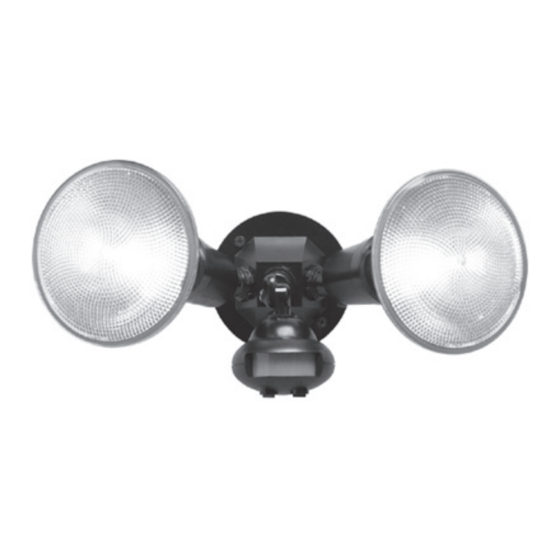
MS34 (Black)
MS34W (White)
ENGLISH
ITEMS REQUIRED
(Purchase separately)
• Phillips screwdriver
• Hammer
• Outdoor weatherproof silicone caulking
• (2) 150 watt (MAX) PAR 38 floodlight bulbs
NOTE: This fixture was designed to work with up to 150 watt maximum PAR halogen flood
bulbs. For improved energy efficiency, lower wattage PAR halogen flood bulbs may be used.
Compact Fluorescent (CFL) bulbs contain electronics which may interfere with the motion
sensing function of your fixture and are not recommended.
HOW IT WORKS
Your motion activated floodlight senses heat images from
objects such as people, large animals and automobile engines.
When motion is detected, the lights will automatically turn
on. Once motion has stopped, the lights will turn off after a
preselected time delay. Your motion activated floodlight may
also be used as a standard floodlight.
WARNINGS AND CAUTIONS
• Read these instructions.
• Keep these instructions.
• Heed all warnings.
• Follow all instructions.
• For outdoor use only.
• cULus LISTED for wet locations.
• Connect fixture to a 120 volt, 60 Hz power source. Any other connection voids the warranty.
• Fixture should be installed by persons with experience in household wiring or by a qualified
electrician. The electrical system, and the method of electrically connecting the fixture to it,
must be in accordance with the National Electrical Code and local building codes.
• Fixture should be mounted to a grounded recessed mounted standard junction box marked
for use in wet locations.
• NOT suitable for ground mount installation.
• Keep away from flammable objects. Do not position fixture within
two inches of any combustible materials.
• Always replace bulb with the same wattage or lower wattage than included. Installing a
bulb of a higher wattage could create a fire hazard. Use of a higher wattage bulb will void
the warranty.
• Do not allow sensor head to touch light housing – maintain at least 1 inch space between
fixture and sensor.
• For proper operation and protection against damage, the motion sensor head adjustment
knobs must be facing the ground.
• MINIMUM 90° C SUPPLY CONDUCTORS.
Questions? / ¿Preguntas ? 1-800-334-6871 ConsumerProducts@cooperlighting.com
PACKAGING CONTENTS / CONTENIDO DEL PAQUETE
A. Motion detector and light fixture
Detector de movimiento y
artefacto de luz
110 degrees
B. Coverplate gasket
Junta de la placa de cubierta
D. (2) #6 and (2) #8 mounting screws
(use the size that fits your junction box)
(2) Tornillos #6 y (2) tornillos #8 de montaje
(utilice el tamaño que mejor se adecue a
su caja de conexión)
• Disassembly of your fixture will void the warranty.
SAVE THESE INSTRUCTIONS.
FOR BEST RESULTS
• Install the motion sensor/transmitter 8-12 feet
above the ground. (Motion sensor is less sensitive
above 12 feet.)
• Locate motion sensor so motion moves across
detection zone (Fig. 1).
• Locate sensor away from heat producing sources to
prevent false triggering. Also be very careful not to
include objects such as windows, white walls and
water in the detection zone.
• Locate sensor away from moving objects such as
trees, large shrubs and street traffic.
Up to
60 feet
• Do not install more than one motion activated
floodlight on one wall switch or the same circuit since
this may cause interference between fixtures.
MOUNTING AND WIRING YOUR FIXTURE
WARNING: Risk of electric shock. Disconnect
power at fuse or circuit breaker before installing
or servicing.
NOTE: Fixture can be wall or eave mounted.
NOTE: Coverplate mounts to recessed mounted
standard junction boxes (Fig. 2). Junction box must be
at least 1-1/2 inch in depth for proper installation for
recessed mount application.
1. Turn off power at main fuse/breaker box.
2. Match up screw holes on the floodlight coverplate
with the junction box screw holes.
3. Thread fixture wires through coverplate
gasket (B) (Fig. 3).
4. Connect fixture black wire to house black wire
and connect fixture white wire to house white wire
using wire nuts (E) provided (Fig. 3). (No ground
wire is required. Attach any ground wire from your
house to junction box.)
5. Attach fixture (A) to the junction box with two
mounting screws (D) provided.
6. Apply silicone caulk around the edges of the
coverplate to provide a watertight seal from rain
and moisture.
7. Insert lampholder gaskets (C) into lampholder
assembly, tightly against lampholder, and screw
bulbs into each lampholder (Fig. 3). (Do not
overtighten bulbs.)
1
Instruction Manual / Instrucciones
C. (2) Lampholder gaskets
(2) Juntas obturadoras
del receptáculo
E. (2) Wire nuts
(2) Tuercas para alambre
Fig. 1
Fig. 2
1-1/2 inch
Round
Fig. 3
E
C
B
A
E
Wall mount
A
Eave mount
1-1/2 inch
Octagonal
D
D
C
Publicidad

Manuales relacionados para Cooper Lighting MS34


Resumen de contenidos para Cooper Lighting MS34
- Página 1 E. (2) Wire nuts (use the size that fits your junction box) (2) Tuercas para alambre (2) Tornillos #6 y (2) tornillos #8 de montaje MS34 (Black) (utilice el tamaño que mejor se adecue a MS34W (White) su caja de conexión) • Disassembly of your fixture will void the warranty.
- Página 2 8. Turn power on at main fuse/breaker box. Problem Cause / Solution 9. Aim sensor head in desired position. NOTE: Maintain air spacing between lamps and Light Comes On There is motion in the detection zone. sensor head, at least 1 inch. Make sure sensor For No Apparent • Make sure the sensor is not picking up moving objects such as head is positioned with control switches facing trees, traffic, etc. Reason At Night towards the ground. TEST FOR YOURSELF. • Cover the sensor lens with cardboard to prevent sensor from OPERATING YOUR FIXTURE detecting motion and cover the photocell on the bottom of the Fig. 4 1. Rotate both knobs on bottom of the sensor to “T” sensor head. If the light stays off, something in the detection (test) (Fig. 4). zone is triggering the sensor. 2.
- Página 3 NOTA: La placa de cubierta se adapta a las cajas Fig. 2 ESPAÑOL eléctricas empotradas (Fig. 2). La caja eléctrica 3,81 cm 3,81 cm debe tener una profundidad mínima de 3,81 cm (1-1/2 in.) para asegurar una instalación adecuada ARTÍCULOS NECESARIOS en aplicaciones empotradas. (se compran por separado) 1. Apague la electricidad desde la caja de fusibles/ • Destornillador en cruz (Phillips) interruptores automáticos principal. Redonda Octagonal • Martillo 2. Haga que agujeros de los tornillos de la placa de • Calafateo de silicona resistente a la intemperie la cubierta del portalámparas coincidan con los Fig. 3 • (2) lámparas para proyector tipo PAR 38 de 150 W (máximo) agujeros de los tornillos de la caja de empalmes. NOTA: Este accesorio fue diseñado para trabajar con bombillas reflectoras de Halógeno PAR de 3. Pase los cables del portalámparas a través de la 150 vatios como máximo. Para mayor eficiencia de energía, use bombillas reflectoras junta de la placa de cubierta (B) (Fig. 3). Halógeno PAR de menor vataje. No se recomienda el uso de bombillas fluorescentes 4. Conecte el cable negro del accesorio al cable negro compactas (CFL) porque tienen partes electrónicas que pueden interferir con las funciones de la caja y el cable blanco del accesorio al cable de detección de movimiento de su accesorio.
- Página 4 GARANTIA LIMITADA DE 2 AÑOS Modo de Adjuste de la perilla Como adjustar funcionamiento de MODO interruptor electrico LA SIGUIENTE GARANTÍA ES EXCLUSIVA Y REEMPLAZA A TODAS LAS DEMÁS GARANTÍAS, YA SEAN IMPLÍCITAS, EXPLÍCITAS O ESTATUTARIAS, INCLUIDAS ENTRE OTRAS, LAS GARANTÍAS Ajuste Estándar de Una (Cualquier posición) Apague la corriente y DE COMERCIABILIDAD E IDONEIDAD PARA UN FIN PARTICULAR. Lámpara de Alta Intensidad enciéndala una vez por el Cooper Lighting, LLC (“Cooper Lighting”) garantiza a sus clientes que los productos de Cooper Las luces deben permanecer interruptor de pared dentro Lighting no presentarán defectos en los materiales y en la fabricación durante un período de encendidas continuamente, de 2 segundos para ajustar dos años desde la fecha de compra. La obligación de Cooper Lighting según esta garantía se durante el día y la noche de nuevo a modo de control limita expresamente al suministro de los productos de reemplazo. Esta garantía se extiende (se debe ajustar a mano).