Publicidad
Enlaces rápidos
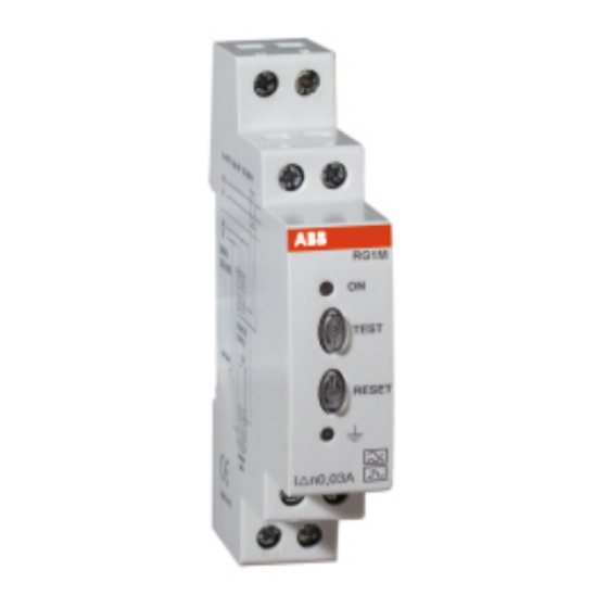
Relé de protección diferencial electrónico RG1M
Código
code
P12204
P12214
1.
DESCRIPCIÓN DEL EQUIPO
Rele de protección diferencial el cual permite una completa protección diferencial asociado a
los transformadores WG. Asegurando la máxima seguridad y continuidad del servicio eléctrico
y evitándose disparos intempestivos
· Acoplable a perfil simétrico DIN 46277 (EN 50022).
· Transformador de corriente toroidal separado modelo WG / WGS.
· La detección de la fuga, se realiza haciendo un muestreo de la intensidad diferencial y
calculando
su verdadero valor eficaz (TRMS).
A
C
D
· Indicación del estado mediante LED´s:
- Led de fuga encendido permanentemente: Relé disparado.
- Led de fuga parpadeando: Det ección de f allo de continuidad
en el transformador. (Relé t ambién dispara)
2.
CONSIDERACIONES INICIALES
2.1. Comprobaciones a la recepción
A la re ce pció n del i nstrumen to co mp rue be el cu mp li mi en to d e los sig uie ntes
pu ntos:
• El eq uip o correspo nd e a l as esp ecifica ci one s d e su pe dido .
• Co mp rueb e qu e el equ ip o no ha sufrid o desp erfecto dura nte el transp orte.
2.2. Precauciones de seguridad
Para la u ti liza ción segu ra de l eq uip o, es fu nda mental que las p erson as qu e lo instal en o ma nip ul en, sig an l as
med ida s d e seg urid ade s h abi tu ale s, a sí como l as adve rte ncia s i nd icad as en di cho man ua l de in str uccion es. El
RG1M es u n e qui po dise ñad o e specífi camen te pa ra i r in sta lad o d entro de un cu adro el éctrico o e nvol vente,
con fija ción a carril DIN. En nin gún caso el eq uip o d ebe ser i nstal ado o i ntegra do en un l ug ar d onde pu ed a
exi sti r u n con ta cto d irecto con l as pe rsona s. RG1M di spo ne de u n LED l umino so de co lor verd e fijo, qu e
ad vierte de su funci ona mien to , y p or l o ta nto, a dvie rte de l a prese ncia de ten sión y corrie nte en el circu ito
el ectróni co. Au nqu e e l L ED l umin oso no esté activo , no exime al usu ari o d e co mprob ar q ue el eq uip o e stá
de scone cta do.
3.
INSTALACIÓN Y PUESTA EN MARCHA
El presente manual contiene informaciones y advertencias que el usuario debe respetar para garantizar el
funcionamiento seguro del equipo, y mantenerlo en buen estado en cuanto a la seguridad. En su
funcionamiento habitual no debe ser utilizado hasta su colocación definitiva dentro del cuadro eléctrico.
Si se utiliza el equipo de forma no especificada por el fabricante, la protección
del equipo puede resultar comprometida
Cuando sea probable que el equipo haya perdido la protección de seguridad (por ejemplo, si presenta daños
visibles), debe desconectarse la alimentación del equipo. En este caso, póngase en contacto con el servicio
técnico cualificado, o bien contacte con nuestro Servicio de Asistencia Técnica SAT (véase apartado 7.-
SERVICIO ASISTENCIA TÉCNICA).
3.1. Instalación del equipo
La instalación del equipo es de tipo carril DIN; tiene una superficie de 1 módulo DIN, y una altura de 90 mm.
Todas las conexiones quedan en el interior del cuadro eléctrico.
A tener en cuenta, que con el equipo conectado, los bornes y la apertura de cubiertas o eliminación de
elementos, pueden dar acceso a partes peligrosas al tacto. El equipo no debe ser utilizado ni alimentado
hasta que haya finalizado por completo su instalación. El equipo debe conectarse a un circuito de
alimentación protegido con fusibles, acorde con el rango de alimentación y consumo del mismo. A su vez, el
circuito de alimentación debe estar provisto de un interruptor magnetotérmico o dispositivo equivalente para
desconectar el equipo de la red de alimentación. El circuito de alimentación, debe conectarse con un cable de
sección mínima de 1 mm2.
Sensibilidad (A)
Tipo
Retardo disparo (s)
Sensivity
Type
Tripping delay
Fija/Fixed: 0.03
RG1M-0,03
RG1M-0,3
Fija/Fixed: 0.3
A Led funcionamiento / Power led
B Pulsador de TEST del relé / Push-button for
B
the relay's TEST
C Pulsador de rearme del relé / Push-button for
the relay's RESET
D Led indicador de estado de la protección
diferencial
Indicative led of the residual current protection
system status
¡IMPORTANTE!
1.
The relay RG1M and the transformer of the WG series enable a full earth leakage
protection for both single and threephase lines. They guarantee maximum security
and continuity of the electrical service, avoiding unwanted tripping
Fija/Fixed: 0.02
· To be fit onto symmetrical rail DIN 46277 (EN 50022)
Fija/Fixed: 0.02
· To work together with an external differential transformer WG / WGS model.
· The detection of the leakage is completed by sampling the residual current
· Status indication by means of LED's:
2.
2.1. Checks on reception
On recei ving the i nstrumen t, check the foll owi ng po ints:
2.2. Safety precautions
The sta ff u si ng or h and lin g the uni t mu st fo llo w th e co mmo n sa fe ty measu res a nd
wa rnin gs incl ude d in the in stru cti on man ual .
The R G1 M uni t h as be en sp ecifical ly d esig ned for i ts i nstall ation in co ntrol p ane l or
en clo su re fi xed to a DIN rai l
a pla ce wh ere peo ple may h ave d ire ct co ntact. Th e RG1 M has a fixed gre en L ED
wh en it is in op eratio n; there fo re, it sh ows th at there is vol ta ge and curre nt in the
el ectroni c ci rcuit. The u ser must make su re that th e uni t is no t con nected to the
po wer sup ply at all time s, eve n whe n de LED i s n ot fla shin g.
3.
The user must take into account and observe the information and warnings included
in this manual to guarantee the correct operation of the unit and comply with the
safety specifications. The unit must not be turned on until it is fully installed in the
electrical panel.
Disconnect the unit from the power supply when the unit's safety protection systems
are not working or there are signs of a problem (for example, in the case of visible
damage). In this case, contact a qualified technical service or contact our Technical
Assistance Service TAS (see section 7.- TECHNICAL ASSISTANCE SERVICE).
3.1. Installing the equipment
The unit will be installed on DIN rails. It has a surface for 1 DIN modules and a
height of 90 mm. All connections remain inside the electric panel.
All connections remain inside the electric panel. Remember that with the unit
connected, the terminals may be hazardous to the touch, and opening the covers or
removing elements may provide access to parts that are dangerous to the touch.
The unit must not be used or powered until it is fully installed. The unit must be
connected to a power supply circuit protected with fuses. The fuses' specifications
will comply with the power supply range and its consumption. Likewise, the power
supply circuit must have a built-in circuit breaker or equivalent device to disconnect
the unit from the power supply network. The power supply circuit must be connected
with a cable that has a minimum section of 1 mm2.
4. Dimensiones /Dimensions
DESCRIPTION OF THE UNIT
and then calculating its true RMS value.
- Leakage led permanently lit: Trip of the relay.
- Leakage led: detection of a transformer's continuity
failure. (Relay trips as well)
PRELIMINARY CONSIDERATIONS
·
The un it's speci fi cati ons a re th e same as th ose on yo ur orde r.
·
Ch eck th at the d evice h as not su ffe red an y da mage d urin g
transp ort.
.
The eq uip me nt mu st n ever be i nstall ed o r i ntegra te d in
INSTALLATION AND START-UP
IMPORTANT!
The unit's protection systems might not be effective
if the unit is used for purposes other than those specified by the manufacturer.
(mm)
66.07
71.73
17.50
M98229312-20-10B
Publicidad

Manuales relacionados para ABB RG1M-0,03


Resumen de contenidos para ABB RG1M-0,03
- Página 1 Type Tripping delay and continuity of the electrical service, avoiding unwanted tripping Fija/Fixed: 0.03 Fija/Fixed: 0.02 P12204 RG1M-0,03 · To be fit onto symmetrical rail DIN 46277 (EN 50022) RG1M-0,3 Fija/Fixed: 0.3 Fija/Fixed: 0.02 P12214 · To work together with an external differential transformer WG / WGS model.
- Página 2 - En caso de cualquier duda de funcionamiento o avería del equipo avisar al servicio de asistencia técnica de ABB. - If you have any doubts about the running of the unit or any faults, contact the service staff of ABB.