Tabla de contenido
Publicidad
Idiomas disponibles
Idiomas disponibles
Enlaces rápidos
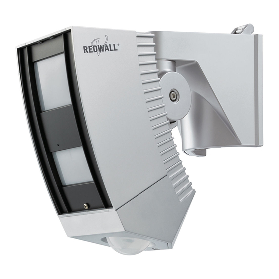
INSTALLATION INSTRUCTIONS
Synthesized Intelligent PIR
Synthesized Intelligent PIR
REDWALL-V series
REDWALL-V series
FEATURES
* Intelligent PIR Detection System
- Three dual pyro-elements with patented Double Conductive
Shielding
- Detection of ambient temperature and illuminance for
automatic sensitivity management
- Advanced detection algorithm
* Anti-vandalism functions
- Max.4 m (13 ft.) installation height
- Anti-rotation with 3-axis accelerometer
- Anti-masking with photo-beam
* Sensitivity selector for near/far area independently
* Detection logic selector
* Detection range selector
* Independent N.C. and N.O. ALARM output
* Adjustable alarm interval time
* Reinforced polycarbonate housing
REDWALL-V
: Synthesized Intelligent PIR
•
SIP-3020
•
SIP-4010
•
SIP-404
1
PARTS IDENTIFICATION
Base
Main unit
Fixing screw
for the base
Adjustment screws
(two facing each other)
Angle adjustment guide
Arrow marking
Fixing screw
NO.5914940
REDWATCH-V
: Synthesized Intelligent PIR
with D/N camera
•
SIP-3020CAM DN (EU)
•
SIP-3020CAM DN (US)
Far area mirror
Masking plate for far area
Fixing rubber form
Window
Fixing rubber
Fixing screw
form (*1)
for the cover
Masking plate for near
Cover
area (*1)
Near area mirror
*1: Not used for the SIP-4010 and SIP-404.
SIP-3020CAM DN
Camera unit
2
INSTALLATION AND MAINTENANCE NOTES
Warning
Never repair or
modify product
Nylon wire
loop
When servicing, the sensor
can be hooked onto the
base using the nylon wire
loop.
2-1
INSTALLATION HINTS
2.3-4.0 m
(7.6-13 ft.)
Mount the detector so that the majority of traf¿ c À ow is across the detection pattern.
- 1 -
Caution
Hold the main unit
securely when you
install or service it.
If you remove your
hands from the main
unit when cables are
connected to it, the
main unit may fall
and the connector
cables may break
or the circuit board
may be damaged.
Caution
Verify that the
power is off before
connecting the
wiring.
Publicidad
Tabla de contenido

Manuales relacionados para Optex REDWALL V Serie


Resumen de contenidos para Optex REDWALL V Serie
- Página 1 NO.5914940 INSTALLATION AND MAINTENANCE NOTES INSTALLATION INSTRUCTIONS Warning Caution Synthesized Intelligent PIR Synthesized Intelligent PIR Hold the main unit securely when you install or service it. REDWALL-V series REDWALL-V series If you remove your hands from the main unit when cables are connected to it, the FEATURES main unit may fall...
-
Página 2: Wall Mounting
INSTALLATION AND ANGLE ADJUSTMENT Wall Mounting Inside View of the Base Base Attach the paper template (an accessory) onto the wall, Main unit connector Waterproof seal and drill a 6-mm dia. mounting hole and a cabling hole. Wall mounting hole (Do not remove Insert the anchor bolt (an accessory) into the board mount this seal.) - Página 3 Adjust the angle of the main unit in a horizontal direction so Power wires should not exceed the following lengths. that you can cover the desired detection area. SIP-3020CAM DN (EU) SIP-3020/SIP-4010/SIP-404 WIRE SIP-3020CAM DN (US) Rotate the main unit. GAUGE 12V DC 14V DC...
- Página 4 Mount the area viewfinder. Locate the center circle of the area Center circle of the lens plate on the center circle of the lens Center circle of the of the area view¿ nder, and check the area plate Put the red string detection area pattern on the area round the main unit.
-
Página 5: Function Setting
Detection Logic Selector Switch Cautions>> Dip switch When you are checking the detection area, take care not to cover the shaded area of the window with the walk Applicable SIP-3020 SIP-4010 SIP-404 SIP-3020CAM DN models tester or its cable. If infrared beams to the sensor are The near area sensor has two dual-element partially shielded, the detection sensitivity will drop and devices, and it covers two types of plane areas... - Página 6 DETECTION AREA Applicable Applicable SIP-3020 SIP-4010 SIP-404 SIP-3020CAM DN SIP-3020 SIP-4010 SIP-404 SIP-3020CAM DN models models TOP VIEW TOP VIEW [ft.] (Installation height 4.0 m (13ft.)) [ft.] (Installation height 4.0 m (13ft.)) [ft.] SIDE VIEW (Installation height 4.0 m (13ft.)) : Near area : Far area 40 [m]...
-
Página 7: Top View
Masking the Far Area Sensor The far area mirror mounted in the main unit has 2 far masking Applicable SIP-3020 SIP-4010 SIP-404 SIP-3020CAM DN plates; one at the right side of this mirror and the other at the left models TOP VIEW (Installation height 4.0 m (13ft.)) [ft.]... - Página 8 MASKING THE NEAR AREA SENSOR Applicable SIP-3020 SIP-4010 SIP-404 SIP-3020CAM DN Masking the Detection Areas using models Masking Plates Remove the masking plate from the storage, and check the detection Attach the masking plate to the mirror, area and the mirror you use by The near area mirror mounted in the main unit has 2 near and secure it to the ribs.
- Página 9 ADJUSTMENT OF CAMERA Adjustment of Camera Masking the Detection Areas using Masking Seals Applicable SIP-3020 SIP-4010 SIP-404 SIP-3020CAM DN models Using the tweezers (an accessory), carefully attach the area Open the camera cover, and connect the monitor unit cable masking seals (an accessory) to the near area mirror. to the camera unit.
-
Página 10: Operation Test
OPERATION TEST Termination Procedure 10-1 If There is a Public Street Where a People Walk or Cars Drive by the Detection Area Applicable SIP-3020 SIP-4010 SIP-404 SIP-3020CAM DN models Points>> After you have adjusted all sensor items, securely tighten all Reduce the size of the detection area so that it does not adjustment screws that you have loosened. - Página 11 SPECIFICATIONS 12-1 Speci¿ cations of the Main Unit 10-2 If Tree Branches or Grass are Detected When They Move Within the Detection Area Applicable SIP-3020 SIP-4010 SIP-404 SIP-3020CAM DN models Points>> SIP-3020 Model SIP-3020 SIP-4010 SIP-404 CAM DN Adjust the detection area so that it does not cover tree branches or grass that move when the wind blows.
- Página 12 (4.0) (10.5) Specifications and design are subject to change without prior notice. OPTEX CO., LTD. (JAPAN) (3.78) (3.6) (ISO 9001 Certi¿ ed by LRQA) (ISO 14001 Certi¿ ed by JET) (0.83) 5-8-12 Ogoto Otsu Shiga 520-0101 JAPAN (0.83)
-
Página 13: Identification De Pièces Détachées
NO.5914940 NOTES D’INSTALLATION ET DE MAINTENANCE INSTRUCTIONS D’INSTALLATION Avertissement Attention Capteur infrarouge passif (PIR) intelligent synthétisé Capteur infrarouge passif (PIR) intelligent synthétisé Sécurisez l’unité principale lors de son installation ou Série REDWALL-V Série REDWALL-V de son entretien. Si vous ne retenez pas l’unité... -
Página 14: Montage Au Mur
INSTALLATION ET RÉGLAGE DES ANGLES Montage au mur Vue interne de la base Montez le gabarit en papier (accessoire) au mur et percez Connecteur de l’unité un trou de 6 mm de diamètre pour le montage, ainsi qu’un Base principale Joint étanche trou de câblage. -
Página 15: Paramètre De La Zone De Détection
Réglez l’angle de l’unité principale à l’horizontale. Les câbles électriques ne doivent pas dépasser les longueurs Ainsi, vous pouvez couvrir la zone de détection souhaitée. suivantes. SIP-3020CAM DN (UE) Faites pivoter l’unité principale. SIP-3020/SIP-4010/SIP-404 CÂBLES SIP-3020CAM DN (US) JAUGE 12V CC 14V CC 24 V CA 12V CC 0,33 mm... -
Página 16: Astuces De Réglage
Localisez le cercle central de la Installez le viseur de zone. Cercle central de la lentille plaque de zone sur le cercle central Cercle central de la de la lentille du viseur puis véri¿ ez plaque de zone Placez la ¿ celle rouge le modèle de la zone de détection autour de l’unité... -
Página 17: Paramètre De Fonction
Commutateur de logique de détection Attention>> Commutateur DIP Lorsque vous vérifiez la zone de détection, pensez à ne pas recouvrir la zone ombrée de la fenêtre avec le testeur Modèles SIP-3020 SIP-4010 SIP-404 SIP-3020CAM DN applicables de mouvement ou son câble. Si les faisceaux infrarouges Le capteur de portée courte est constitué... -
Página 18: Zone De Détection
ZONE DE DÉTECTION Modèles Modèles SIP-3020 SIP-4010 SIP-404 SIP-3020CAM DN SIP-3020 SIP-4010 SIP-404 SIP-3020CAM DN applicables applicables VUE EN PLAN VUE EN PLAN [ft.] (Hauteur d’installation 4,0 m (13 ft.)) [ft.] (Hauteur d’installation 4,0 m (13 ft.)) [ft.] VUE LATÉRALE (Hauteur d’installation 4,0 m (13 ft.)) : Portée courte : Portée longue... - Página 19 Masquage du capteur de portée longue Le miroir de portée longue, installé sur l’unité principale, comporte Modèles SIP-3020 SIP-4010 SIP-404 SIP-3020CAM DN deux plaques de masquage de portée longue ; l’une à sa droite et applicables VUE EN PLAN (Hauteur d’installation 4,0 m (13 ft.)) [ft.] l’autre à...
- Página 20 MASQUAGE DU CAPTEUR DE PORTÉE COURTE Modèles SIP-3020 SIP-4010 SIP-404 SIP-3020CAM DN Masquage des zones de détection à applicables l’aide des plaques de masquage Déballez la plaque de masquage et véri¿ ez la zone de détection et le Attachez la plaque de masquage au miroir utilisés en vous reportant au Le miroir de portée courte, installé...
-
Página 21: Réglage De La Caméra
RÉGLAGE DE LA CAMÉRA Réglage de la caméra Masquage des zones de détection à l’aide des joints de masquage Modèles SIP-3020 SIP-4010 SIP-404 SIP-3020CAM DN applicables Utilisez les brucelles (accessoire), montez soigneusement les Ouvrez le cache de la caméra et connectez le câble du joints de masquage (accessoire) sur le miroir de zone courte. - Página 22 TEST D’OPÉRATION Procédure de clôture 10-1 S’il existe une voie publique où se promènent des piétons ou roulent des voitures à proximité de la zone de détection Modèles SIP-3020 SIP-4010 SIP-404 SIP-3020CAM DN applicables Remarques>> Après avoir réglé tous les éléments du capteur, sécurisez Réduisez la taille de la zone de détection de sorte qu’elle toutes les vis de réglage que vous avez desserrées.
-
Página 23: Fonctions De La Diode Photoémettrice
SPÉCIFICATIONS 12-1 Spéci¿ cations de l’unité principale 10-2 Détection de branches d’arbres ou de l’herbe En cas de mouvement dans la zone de détection Modèles SIP-3020 SIP-4010 SIP-404 SIP-3020CAM DN applicables Remarques>> SIP-3020 Modèle SIP-3020 SIP-4010 SIP-404 CAM DN Réglez la zone de détection de sorte qu’elle exclut les branches ou l’herbe bougeant au vent. - Página 24 SIP-3020/4010/404 Les spécifications et le concept peuvent être modifiés sans (4,0) (10,5) préavis. OPTEX CO., LTD. (JAPON) (ISO 9001 certi¿ é par LRQA) (ISO 14001 certi¿ é par JET) (3,78) (3,6) 5-8-12 Ogoto Otsu Shiga 520-0101 JAPON (0,83) TEL : +81-77-579-8670 FAX : +81-77-579-8190 URL:http://www.optex.co.jp/e/...
- Página 25 NR. 5914940 HINWEISE ZU INSTALLATION UND WARTUNG INSTALLATIONSHINWEISE Warnung Vorsicht Synthetisierter, intelligenter PIR-Bewegungsmelder Synthetisierter, intelligenter PIR-Bewegungsmelder Das Hauptgerät sicher festhalten, wenn Sie es REDWALL-V Serie REDWALL-V Serie einbauen oder warten. Wenn Sie Ihre MERKMALE Hände vom Hauptgerät * Intelligentes PIR-Erfassungssystem entfernen, während - Drei duale Pyroelemente mit patentiertem Double Conductive Kabel daran...
- Página 26 INSTALLATION UND WINKELEINSTELLUNG Wandmontage Innenansicht der Halterung Anschluss für Befestigen Sie die Papierschablone (Zubehör) an Halterung Hauptgerät Wasserfeste Folie der Wand und bohren Sie ein Loch für die Montage Wandmontagebohrung (Diese Folie (Durchmesser 6 mm) und ein Loch für die Kabelführung. nicht entfernen.) Setzen Sie die Ankerschraube (Zubehör) in die Montagebohrung ein.
- Página 27 Stellen Sie den Winkel des Hauptgeräts in einer Stromkabel sollten die folgenden Längen nicht überschreiten. horizontalen Richtung so ein, dass der gewünschte SIP-3020CAM DN (EU) KABEL- SIP-3020/SIP-4010/SIP-404 Erfassungsbereich detektiert wird. SIP-3020CAM DN (US) DURCH- Hauptgerät drehen. MESSER 12 V DC 14V DC 24 V AC 12 V DC 0,33 mm 1370...
- Página 28 Lokalisieren Sie den Mittelkreis der Montieren Sie den Bereichssucher. Mittelkreis des Objektivs Bereichsplatte auf dem Mittelkreis Mittelkreis der des Objektivs des Bereichssuchers Bereichsplatte Den roten Faden um das und überprüfen Sie das Muster Hauptgerät legen. des Erfassungsbereichs auf Roter Faden zum Halten der Bereichsplatte und der Bereichsplatte des Hauptgeräts.
- Página 29 Wahlschalter für die Erfassungslogik Vorsicht>> Dip-Schalter Wenn Sie den Erfassungsbereich überprüfen, müssen Sie darauf achten, dass Sie den schattierten Gilt für folgende SIP-3020 SIP-4010 SIP-404 SIP-3020CAM DN Modelle Bereich des Fensters nicht mit dem Signalgenerator Der Nahbereichssensor enthält zwei (Gehtester) oder seinen Kabeln abdecken. Wenn die Dualelemente und er erfasst damit zwei Typen Infrarotstrahlen des Sensors teilweise abgeschirmt von Flächen, indem er die zwei Elemente...
- Página 30 ERFASSUNGSBEREICH Gilt für folgende Gilt für folgende SIP-3020 SIP-4010 SIP-404 SIP-3020CAM DN SIP-3020 SIP-4010 SIP-404 SIP-3020CAM DN Modelle Modelle DRAUFSICHT DRAUFSICHT [ft.] (Installationshöhe 4,0 m (13 ft.)) [ft.] (Installationshöhe 4,0 m (13 ft.)) [ft.] SEITENANSICHT (Installationshöhe 4,0 m (13 ft.)) : Nahbereich : Fernbereich 40 [m]...
- Página 31 Abdecken des Fernbereichssensors Der in das Hauptgerät eingebaute Fernbereichsspiegel enthält Gilt für folgende SIP-3020 SIP-4010 SIP-404 SIP-3020CAM DN 2 Abdeckblenden für den Fernbereich; eine auf der rechten Modelle DRAUFSICHT (Installationshöhe 4,0 m (13 ft.)) [ft.] Seite des Spiegels und eine auf der linken Seite des Spiegels. Sie können den Erfassungsbereich abdecken, indem Sie die Winkel Kamerablicks:...
- Página 32 ABDECKEN DES NAHBEREICHSSENSORS Gilt für folgende SIP-3020 SIP-4010 SIP-404 SIP-3020CAM DN Abdecken der Erfassungsbereiche mit Modelle Abdeckblenden Nehmen Sie die Abdeckblende aus dem Befestigen Sie die Abdeckblende am Aufbewahrungsplatz und überprüfen Sie den Spiegel und sichern Sie sie an den von Ihnen verwendeten Erfassungsbereich Der in das Hauptgerät eingebaute Nahbereichsspiegel enthält Rippen.
- Página 33 EINSTELLUNG DER KAMERA Einstellung der Kamera Abdecken der Erfassungsbereiche mit Abdeckfolien Gilt für folgende SIP-3020 SIP-4010 SIP-404 SIP-3020CAM DN Modelle Befestigen Sie die Abdeckfolie (Zubehör) vorsichtig mit der Öffnen Sie die Kameraabdeckung und schließen Sie das Pinzette (Zubehör) am Nahbereichsspiegel. Kabel der Monitoreinheit an die Kameraeinheit an.
- Página 34 BETRIEBSTEST Beenden der Einstellung 10-1 Wenn sich im Erfassungsbereich eine öffentliche, von Fußgängern und Fahrzeugen benutzte Straße be¿ ndet Gilt für folgen- SIP-3020 SIP-4010 SIP-404 SIP-3020CAM DN de Modelle Bemerkung>> Nachdem Sie alle Sensoreinstellungen vorgenommen Verringern Sie die Größe des Erfassungsbereichs so, dass haben, ziehen Sie sorgfältig alle gelösten keine öffentlichen Straßen umfasst werden.
-
Página 35: Technische Daten
TECHNISCHE DATEN 12-1 Technische Daten des Hauptgeräts 10-2 Wenn Äste oder Grashalme erfasst werden, die sich im Erfassungsbereich bewegen Gilt für folgende SIP-3020 SIP-4010 SIP-404 SIP-3020CAM DN Modelle Bemerkung>> SIP-3020 Modell SIP-3020 SIP-4010 SIP-404 CAM DN Stellen Sie den Erfassungsbereich so ein, dass sich keine Äste oder Grashalme darin befinden, die sich durch den Erfassungsmethode Passiv-Infrarot... - Página 36 (4,0) (10,5) Die technischen Daten und das Design können ohne vorherige Bekanntgabe geändert werden. (3,78) OPTEX CO., LTD. (JAPAN) (3,6) (ISO 9001 zerti¿ ziert von LRQA) (ISO 14001 zerti¿ ziert von JET) (0,83) 5-8-12 Ogoto Otsu Shiga 520-0101 JAPAN (0,83) TEL: +81-77-579-8670 FAX: +81-77-579-8190 URL:http://www.optex.co.jp/e/...
- Página 37 N. 5914940 NOTE PER L'INSTALLAZIONE E LA MANUTENZIONE ISTRUZIONI PER L'INSTALLAZIONE Attenzione Attenzione PIR intelligente combinato PIR intelligente combinato Mantenere fermamente l'unità durante Serie REDWALL-V Serie REDWALL-V l'installazione e la manutenzione. Se si lascia l'unità principale quando CARATTERISTICHE ad essa sono collegati cavi, può...
-
Página 38: Montaggio A Parete
INSTALLAZIONE E REGOLAZIONE DELL'ANGOLO Montaggio a parete Vista interna della base Connettore unità Appendere il modello in carta (accessorio) alla parete, quindi praticare Base principale un foro di montaggio del diametro di 6 mm e un foro per i cavi. Guarnizione impermeabile Inserire il bullone di ancoraggio (accessorio) nel foro di montaggio Foro di montaggio a parete... - Página 39 Regolare l'angolo dell'unità principale in direzione orizzontale I cavi di alimentazione non devono superare le lunghezze indicate nella tabella. in modo da poter coprire l'area di rilevamento desiderata. SIP-3020CAM DN (EU) SIP-3020/SIP-4010/SIP-404 DIMENSIONE SIP-3020CAM DN (US) Ruotare l'unità principale. CAVO 12 Vcc 14 Vcc 24 Vca...
-
Página 40: Suggerimenti Per Il Montaggio
Individuare il cerchio centrale della Montare il mirino di area. Cerchio centrale della lente placca di area nel cerchio centrale della Cerchio centrale lente del mirino di area e veri¿ care della placca di area Collocare la stringa rossa l'area di rilevamento sulla placca di intorno all'unità... - Página 41 Selettore della logica di rilevamento Attenzione>> Dip switch Quando si verifica l'area di rilevamento, prestare attenzione a non coprire l'area ombreggiata della finestra con il walk tester Modelli SIP-3020 SIP-4010 SIP-404 SIP-3020CAM DN o con il suo cavo. Se il fascio di raggi infrarossi verso il sensore Il sensore dell'area vicina dispone di due dispositivi è...
- Página 42 AREA DI RILEVAMENTO Modelli Modelli SIP-3020 SIP-4010 SIP-404 SIP-3020CAM DN SIP-3020 SIP-4010 SIP-404 SIP-3020CAM DN VISTA DALL'ALTO VISTA DALL'ALTO (altezza di installazione 4,0 m (13 ft.)) (altezza di installazione 4,0 m (13 ft.)) [ft.] [ft.] [ft.] VISTA LATERALE (altezza di installazione 4,0 m (13 ft.)) : Area vicina : Area distante 40 [m]...
-
Página 43: Vista Dall'alto
Mascheramento del sensore di area distante Lo specchio di area distante montato nell'unità principale dispone Modelli SIP-3020 SIP-4010 SIP-404 SIP-3020CAM DN di due placche di mascheramento distante; una a destra e una a VISTA DALL'ALTO (altezza di installazione 4,0 m (13 ft.)) sinistra dello specchio. - Página 44 MASCHERAMENTO DEL SENSORE DELL'AREA VICINA Modelli SIP-3020 SIP-4010 SIP-404 SIP-3020CAM DN Mascheramento delle aree di rilevamento con le placche di mascheramento Estrarre la placca di mascheramento dall'alloggiamento e veri¿ care l'area Applicare la placca di mascheramento di rilevamento e lo specchio facendo Lo specchio di area vicina montato nell'unità...
-
Página 45: Regolazione Della Telecamera
REGOLAZIONE DELLA TELECAMERA Regolazione della telecamera Mascheramento delle aree di rilevamento con i contrassegni di mascheramento Modelli SIP-3020 SIP-4010 SIP-404 SIP-3020CAM DN Utilizzando le pinzette (accessorie), applicare i contrassegni di Aprire il coperchio della telecamera e collegare il cavo del mascheramento di area (accessori) allo specchio di area vicina. -
Página 46: Test Di Funzionamento
TEST DI FUNZIONAMENTO Procedura ¿ nale 10-1 Se è presente una strada pubblica in cui camminano persone o passano auto nell'area di rilevamento Modelli SIP-3020 SIP-4010 SIP-404 SIP-3020CAM DN Importante>> Dopo avere regolato tutti gli elementi del sensore, bloccare Ridurre le dimensioni dell'area di rilevamento in modo che tutte le viti di regolazione che sono state allentate. - Página 47 SPECIFICHE 12-1 Speci¿ che dell'unità principale 10-2 Se vengono rilevati rami o erba quando si muovono nell'area di rilevamento Modelli SIP-3020 SIP-4010 SIP-404 SIP-3020CAM DN Importante>> SIP-3020 Modello SIP-3020 SIP-4010 SIP-404 CAM DN Regolare l'area di rilevamento in modo che non copra rami o erba in movimento con il vento.
- Página 48 (4,0) (10,5) Le specifiche e il design sono soggetti a cambiamenti senza preavviso. OPTEX CO., LTD. (GIAPPONE) (3,78) (3,6) (Certi¿ cata ISO 9001 da LRQA) (Certi¿ cata ISO 14001 da JET) (0,83) 5-8-12 Ogoto Otsu Shiga 520-0101 GIAPPONE (0,83) TEL.:+81-77-579-8670 FAX:+81-77-579-8190...
-
Página 49: Pir Inteligente Sintetizado
NO.5914940 NOTAS DE INSTALACIÓN Y MANTENIMIENTO INSTRUCCIONES DE INSTALACIÓN Advertencia Precaución PIR inteligente sintetizado PIR inteligente sintetizado Sujete la unidad principal fuertemente Serie REDWALL-V Serie REDWALL-V cuando instale o realice tareas de mantenimiento. FUNCIONES Si retira las manos de la unidad * Sistema de detección PIR inteligente principal cuando - Tres piro elementos duales con apantallamiento conductivo... -
Página 50: Instalación Y Ajuste Del Ángulo
INSTALACIÓN Y AJUSTE DEL ÁNGULO Montaje en pared Vista interior de la base Coloque la plantilla de papel (un accesorio) sobre la pared Conector de unidad Base principal y taladre un orificio de montaje de 6 mm de diámetro y un Precinto impermeable orificio de cableado. -
Página 51: Configuración De La Zona De Detección
Ajuste el ángulo de la unidad principal en dirección Los cables de alimentación no deben exceder las siguientes longitudes. horizontal de modo que pueda cubrir la zona de detección SIP-3020CAM DN (EU) SIP-3020/SIP-4010/SIP-404 CABLE que desee. SIP-3020CAM DN (EE.UU.) CALIBRE Gire la unidad principal. -
Página 52: Sugerencias De Ajuste
Sitúe el círculo central de la placa Monte el visor de zona. Círculo central del objetivo de zona en el círculo central de la Círculo central de la lente del visor de zona y compruebe placa de zona Rodee la unidad principal el patrón de zona de detección de la con tira de color rojo. -
Página 53: Configuración De Funciones
Interruptor selector de lógica de detección Precauciones>> Interruptor para bascular Cuando compruebe la zona de detección, tenga cuidado de no cubrir la zona sombreada de la ventana con el controlador Modelos SIP-3020 SIP-4010 SIP-404 SIP-3020CAM DN aplicables de movimiento o su cable. Si los rayos infrarrojos del sensor El sensor de zona cercana tiene dos dispositivos con están parcialmente apantallados, la sensibilidad de detección elementos dobles y cubre dos tipos de zonas planas... -
Página 54: Zona De Detección
ZONA DE DETECCIÓN Modelos Modelos SIP-3020 SIP-4010 SIP-404 SIP-3020CAM DN SIP-3020 SIP-4010 SIP-404 SIP-3020CAM DN aplicables aplicables VISTA SUPERIOR VISTA SUPERIOR [ft.] (altura de instalación de 4,0 m (13 ft.)) [ft.] (altura de instalación de 4,0 m (13 ft.)) [ft.] VISTA LATERAL (altura de instalación de 4,0 m (13 ft.)) : Zona cercana... -
Página 55: Vista Superior
Enmascaramiento del sensor de zona lejana El espejo de zona lejana montado en la unidad principal tiene Modelos SIP-3020 SIP-4010 SIP-404 SIP-3020CAM DN 2 placas de enmascaramiento lejanas; una en el lado derecho aplicables VISTA SUPERIOR (altura de instalación de 4,0 m (13 ft.)) [ft.] de este espejo y la otra en el lado izquierdo. -
Página 56: Enmascaramiento Del Sensor De Zona Cercana
ENMASCARAMIENTO DEL SENSOR DE ZONA CERCANA Modelos SIP-3020 SIP-4010 SIP-404 SIP-3020CAM DN Ocultación de las zonas de detección con aplicables las placas de enmascaramiento Extraiga la placa de enmascaramiento del embalaje y compruebe la zona de Coloque la placa de enmascaramiento detección y el espejo, consultando el El espejo de zona cercana montado en la unidad principal tiene en el espejo y fíjela a los montantes. -
Página 57: Ajuste De La Cámara
AJUSTE DE LA CÁMARA Ajuste de la cámara Ocultación de las zonas de detección con los precintos de enmascaramiento Modelos SIP-3020 SIP-4010 SIP-404 SIP-3020CAM DN aplicables Con las pinzas (un accesorio), coloque cuidadosamente los Abra la cubierta de la cámara y conecte el cable de la precintos de enmascaramiento (un accesorio) en el espejo de unidad del monitor a la unidad de la cámara. -
Página 58: Prueba De Funcionamiento
PRUEBA DE FUNCIONAMIENTO Procedimiento de ¿ nalización 10-1 Si hay una calle con gente caminando o coches circulando en la zona de detección Modelos SIP-3020 SIP-4010 SIP-404 SIP-3020CAM DN aplicables Notas>> Una vez haya ajustado todos los elementos del sensor, Reduzca la zona de detección para que no enfoque una apriete todos los tornillos de ajuste que haya aflojado. -
Página 59: Especificaciones
ESPECIFICACIONES 12-1 Especi¿ caciones de la unidad principal 10-2 Si se detectan ramas de árboles o briznas de hierba Cuando pasan por la zona de detección Modelos SIP-3020 SIP-4010 SIP-404 SIP-3020CAM DN aplicables Notas>> SIP-3020 Modelo SIP-3020 SIP-4010 SIP-404 CAM DN Ajuste la zona de detección de forma que no enfoque ramas de árbol o hierba que se pueda mover con el viento. -
Página 60: Dimensiones
SIP-3020/4010/404 Las especificaciones y el diseño están sujetos a cambio sin previo (4,0) (10,5) aviso. OPTEX CO., LTD. (JAPÓN) (Certi¿ cado ISO 9001 por LRQA) (Certi¿ cado ISO 14001 por JET) (3,78) (3,6) 5-8-12 Ogoto Otsu Shiga 520-0101 JAPÓN (0,83)