Tabla de contenido
Publicidad
Idiomas disponibles
Idiomas disponibles
Enlaces rápidos
Publicidad
Capítulos
Tabla de contenido
Solución de problemas

Manuales relacionados para Progress Lighting HUBBELL P250018


Resumen de contenidos para Progress Lighting HUBBELL P250018
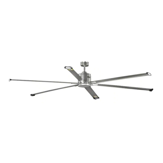
- Página 1 Ceiling Fan Installation Manual P250018...
- Página 2 Limited Lifetime Warranty Progress Lighting fan motors are warranted to the original purchaser to be free of electrical and/or mechanical defects for so Date Purchas ed long as the original purchaser owns the fan. Pull chain switches, reverse switches, capacitors and metal finishes are warranted to be free from defects in materials or workmanship for a period of 1 year from the date of purchase.
-
Página 3: Tabla De Contenido
Safety Rules..................................... Unpacking Your Fan ..................................Installing Your Fan ..................................Installing the Metal Light Cover..............................Operating Your Transmitter ................................Care of Your Fan ................................... Troubleshooting .................................... Specifications ....................................Table of Contents... -
Página 4: Safety Rules
1. To reduce the risk of electric shock, insure electricity has been turned off 9. To avoid personal injury or damage to the fan and other items, be at the circuit breaker or fuse box before beginning. cautious when working around or cleaning the fan. 2. -
Página 5: Unpacking Your Fan 2
Unpack your fan and check the contents. You should have the following items: 12. Loose parts bag containing: a. Blade attachment hardware 1. Fan blades (6) 8. Metal light cover (19 screws, 19 fiber washers) Wall transmitter incl. 2 mounting screws and 2. -
Página 6: Tools Required
BE ACCEPTABLE FOR FAN SUPPORT AND fixture but no ceiling joist, you may need an MAY NEED TO BE REPLACED. CONSULT A installation hanger bar as shown in Figure 4 QUALIFIED ELECTRICIAN IF IN DOUBT. (available at your Progress Lighting Retailer). 3. Installing Your Fan... -
Página 7: Hanging The Fan
the hanger pin through the holes in the collar and Hanging the Fan downrod. Be careful not to jam the pin against the Ceiling UL Listed wiring inside the downrod. Insert the locking pin REMEMBER to turn off the power. Follow hanger electrical through the hole near the end of the hanger pin until it... - Página 8 Make the Electric Connections WARNING: To avoid possible electrical shock, be sure electricity is turned off at the main fuse box before wiring. If you feel you do not have enough electrical wiring knowledge or experience, have your fan installed by a licensed electrician. 1.
- Página 9 Ground conductor Black White Black White Outlet White Black Wall Black Black comtrol Yellow/green ground Wall outlet box Figure 8...
- Página 10 Installing the wall switch Wall outlet box Wall control WARNING: Hook up in "series only". Do not connect the hot and neutral wires of Wall plate the electric circuit to the wall switch - damage to the switch and possible fire could occur.
-
Página 11: Finishing The Installation
Finishing the Installation Outlet box Step 1. Tuck connections neatly into ceiling outlet box. Hanger bracket Step 2. Slide the canopy up to mounting bracket and place the key hole on the canopy over the screw on Screws the mounting bracket, turn canopy until it locks in place at the narrow section of the key holes. -
Página 12: Attaching The Fan Blades
2. Most fan wobbling problems are caused Attaching the Fan when blade levels are unequal. Check this level by selecting a point on the ceiling Blades above the tip of one of the blades. Measure this distance as shown in Figure 12. Rotate the fan until the next blade is positioned for CAUTION: Remove 6 rubber packing mounts measurement. -
Página 13: Installing The Mounting Plate
Installing the Mounting Plate Step 1. Remove 1 of the 3 screws from the mounting ring and loosen the other 2 screws. (Do not remove) Step 2. Place the key holes on the mounting plate over the 2 screws previously loosened from the mounting ring, turn mounting plate until it locks in place at the narrow section of the key holes. -
Página 14: Installing The Metal Light Cover
Before starting installation, CAUTION: disconnect the power by turning off the circuit breaker or removing the fuse at fuse box. Turning power off using the fan switch is not sufficient to prevent electric shock. Position the tabs in the inside of the rim on the metal light cover so they line up with the notches on the inside of the rim on the mounting plate. -
Página 15: Installing The Battery
Wall Control Button Definitions: (Fig. 16) Installing the battery These six buttons are used to set the fan speed as follows: Install a 12V MN21/A23 battery (included) into the 1 = minimum speed wall control. To prevent damage to the remote 2 = low speed Follow the below steps to set the wall control:The auto control, remove the battery if not used for long... - Página 16 This receiver provides the following protective function: 1. Lock Rotor Position: The DC motor has a built-in safety against a stalled or locked rotor condition (stalled blade rotation). If there is an obstruction or fault with the motor, the current monitoring function will automatically turn power off to the motor after 30 seconds.
-
Página 17: Care Of Your Fan
Here are some suggestions to help you maintain your The motor has There is no need to oil your fan. permanently lubricated bearings. 1. Because of the fan's natural movement, some IMPORTANT connections may become loose. Check the support MAKE SURE THE POWER IS OFF AT THE connections, brackets, and blade attachments ELECTRICAL PANEL BOX BEFORE YOU twice a year. -
Página 18: Troubleshooting
Problem Solution Fan will not start 1. Check circuit fuses or breakers. 2. Check line wire connections to the fan and switch wire connections in the switch housing. CAUTION: Make sure main power is off. 3. Check to make sure the dip switches from the transmitter and receiver are set to the same frequency. 4. -
Página 19: Specifications
C.F. 0.072 3.85 26.46 30.53 4.68' 96" 0.47 35.64 High These are approximate measures. They do not include Amps and Wattage used by the light kit. 2019 Progress Lighting, Inc. 701 Millennium Blvd., Greenville, SC 29607 All Rights Reserved Specifications... - Página 20 Manual de Instalación del Ventilador de Techo P250018 93102778_...
-
Página 21: Garantía Limitada De Por Vida
Con comprobante de compra, el comprador original podrá devolver el ventilador defectuoso al lugar de compra, durante los primeros 30 días, para su reemplazo. Pasados los 30 días, el comprador original DEBE contactarse con Progress Lighting al (864) 678-1000 para la reparación o el reemplazo, que se determinará a criterio exclusivo de Progress Lighting y será la compensación única y exclusiva del comprador. - Página 22 Normas de seguridad ..................................Cómo desembalar el ventilador ..............................Cómo instalar el ventilador ................................Instalación del Cubierta de la Luz de Metal ........................... Operando su transmisor ................................Cómo cuidar del ventilador ................................Resolución de problemas ................................Especificaciones .................................... Tabla de Contenido...
-
Página 23: Normas De Seguridad
1. Para reducir el riesgo de eléctrocución, asegurarse de que la eléctricidad se 9. Para evitar lesiones personales o da os al ventilador y otros articulos, ha desactivado en el cortacircuitos o caja de fusibles antes de comenzar. tener cuidado al trabajar cerca del ventilador o al limpiarlo. 2. -
Página 24: Cómo Desembalar El Ventilador 2
Unpack your fan and check the contents. You should have the following items: 1. Juego de aspas (6) 8. Cubierta de la luz de metal 12. Dos bolsas de piezas pequeñas: 2. Escudete superior 9. Transmisor de pared incl. 2 tornillos de montaje y 3. -
Página 25: Herramienta Necesarias
Para colgar su ventilador donde ya existe una DISTRIBUCION instalación pero no una viga de techo, es possible que se necesite una instalación de barra de suspención como se muestra la Figura 4 (disponible en su distribuidor Progress Lighting). 3. Cómo instalar el ventilador... -
Página 26: Colocación Del Ventilador
parte superior de la caja del motor (Fig. 7) Introduzca Colocación del ventilador con cuidado el pasador de suspensión a través de los Soporte de agujeros del cuello y de la barra. Tenga cuidado de Caja de eléctrica montaje RECUERDE desconectar la alimentación. que el pasador no se atasque con los hilos de dentro aprobada Siga estos pasos para colocar correctamente el... -
Página 27: Realizar Las Conexiones Eléctricas
Realizar las Conexiones Eléctricas ADVERTENCIA: Para evitar posibles descargas eléctricas, asegúrese de que la electricidad esté apagada en el cuadro principal de fusibles antes del cableado. Si no tiene los conocimientos necesarios sobre instalaciones eléctricas o experiencia, deje que sea un electricista profesional quien realice la instalación. 1. - Página 28 Conductor Negro Blanco a tierra Negro Blanco Caja de salida Negro Blanco Control Negro Negro de pared Tierra amarillo/Verde Ventilador Caja de salida de pared Figura 8...
-
Página 29: Instalación Del Interruptor De Pared
Instalación del interruptor de pared Caja de conexiones Control de pared ADVERTENCIA: Sólo conecta sólo los “cables en serie”. No conectes los cables Placa de pared positivos y neutros del circuito eléctrico al interruptor del transmisor de pared, puede causar daño al interruptor y un posible incendio. ADVERTENCIA: Recuerda apagar la corriente eléctrica en el cortacircuitos o la caja de fusibles. -
Página 30: Terminando La Instalación
Terminando la Instalación Caja de Paso 1. Meta las conexiónes en forma ordenada salida adentro de la toma de corriente. Abrazadera de Paso 2. Deslice la cubierta hacia arriba hacia el soporte soporte de montaje y coloque el agujero de posición de la cubierta sobre el tornillo del Tornillos soporte de montaje, gire la cubierta hasta que... -
Página 31: Instalacion De Las Aspas
2. La mayoría de los problemas de oscilación se Instalacion de las Aspas originan cuando los niveles de las aspas son desiguales. Revisar esté nivel por medio de seleccionar un punto del techo por encima de la PRECAUCIÓN: Quite los 8 montajes de goma punta de una de las aspas. -
Página 32: Instalación De La Placa De Montaje
Instalación de la Placa de Montaje Paso 1. Quite 1 de los 3 tornillos del anillo de montaje y afloje los otros 2 tornillos. (No los quite) Paso 2. Coloque los agujeros del plato de montaje en los 2 tornillos previamente aflojados del anillo de montaje, gire el plato de montaje hasta que quede fijo en su lugar en la parte estrecha de los agujeros. -
Página 33: Instalación Del Cubierta De La Luz De Metal
PRECAUCIÓN: Antes de comenzar con la instalación, desconecte la alimentación apagando el circuito del automático o quitando el fusible de la caja de fusibles. Para evitar descargas eléctricas, no basta con apagar la alimentación utilizando el interruptor del ventilador. Coloque las lengüetas en el interior del borde de la cubierta de la luz de metal para que se alineen con las muescas en el interior del borde de la placa de montaje. -
Página 34: Instalación De La Bateria
Definición de botón del control de pared. (Fig. 16) Instalación de la Bateria Estos seis botones se utilizan para ajustar la velocidad del ventilador: Instala una batería MN21/A23 de 12V (incluida) en 1 = velocidad mínima el control remoto. Para prevenir daños al control 2 = velocidad baja remoto, sacala batería si no va a usarse por largo 3 = velocidad media baja... - Página 35 El receptor ofrece la siguiente función de protección: 1. Posición de bloqueo: El motor DC tiene una función de seguridad incorporada contra obstrucción durante el uso. El motor será bloqueado y la corriente desconectada tras 30 segundos de interrupción. Quite el obstáculo antes de volver a poner en marcha.
-
Página 36: Cómo Cuidar Del Ventilador
He aqui algunas sugerencias para ayudarle el 3. No hay necesidad de aceitar el ventilador. El motor mantenimiento del ventilodor. tiene cojinetes permanentemente lubricados. 1. Debido al movimiento natural del ventilador, ADVERTENCIA algunas conexiones se podrian aflojar. Examinar las ASEGURARSE DE QUE LA ELECTRICIDAD conexiones del soporte, soportes, y accessorios de las ESTÉ... -
Página 37: Resolución De Problemas
Solución Problema El ventilador noarranca. 1. Revisar los fusibles o interruptores de circuitos. 2. Verificar las conexiones de cables de linea al ventilador y conexiones de cable del interruptor. PRECAUCIÓN: Asegurarse de que la fuente pricipal de electricidad esté desactivada. 3. -
Página 38: Especificaciones
0.072 3.85 26.46 30.53 4.68' (244 cm) Alta 0.47 35.64 Estas son mediciones aproximadas. No incluyen los Amperios y vatios usado por el juego de iliminación. 2019 Progress Lighting, Inc. 701 Millennium Blvd., Greenville, SC 29607 All Rights Reserved Especificaciones...