Tabla de contenido
Publicidad
Idiomas disponibles
Idiomas disponibles
Enlaces rápidos
Zoeller
is a registered trademark
®
of Zoeller Co. All Rights Reserved.
ATTACH YOUR RECEIPT HERE
Serial Number
Questions, problems, missing parts? Before returning to your retailer, call our customer
service department at 1-800-584-8089, 7:30 a.m. - 5:00 p.m., EST, Monday - Friday.
Purchase Date
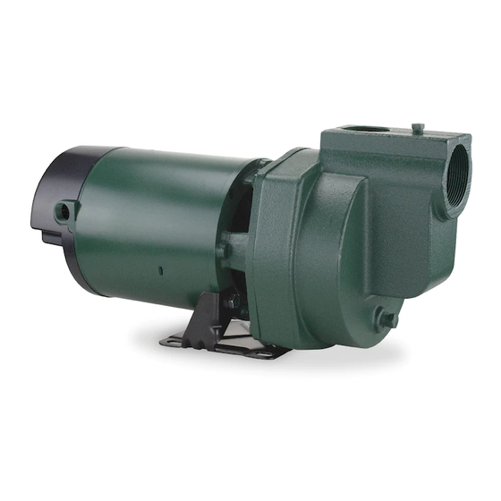
IRRIGATION
PUMPS
MODELS #1332-0006, 1333-0006
Español p. 24
024998 B
Publicidad
Tabla de contenido
Solución de problemas

Manuales relacionados para Zoeller 1332-0006


Resumen de contenidos para Zoeller 1332-0006
- Página 1 IRRIGATION PUMPS MODELS #1332-0006, 1333-0006 Zoeller is a registered trademark ® of Zoeller Co. All Rights Reserved. Español p. 24 ATTACH YOUR RECEIPT HERE Serial Number Purchase Date Questions, problems, missing parts? Before returning to your retailer, call our customer service department at 1-800-584-8089, 7:30 a.m.
-
Página 2: Safety Information
SAFETY INFORMATION Please read and understand this entire manual before attempting to assemble, operate, or install the product. • NOTE: Pumps with the “UL” Mark and pumps with the “US” mark are tested to UL Standard UL778. CSA certified pumps are certified to CSA Standard C22.2 No. 108. (CUS) DANGER ELECTRICAL SHOCK HAZARD. -
Página 3: Package Contents
PACKAGE CONTENTS Description Quantity Pump Foot Valve PREPARATION Before beginning installation of product, make sure all parts are present. Compare parts with package contents drawing. If any part is missing or damaged, do not attempt to assemble the product. Contact customer service for replacement parts. -
Página 4: General Pump Information
GENERAL PUMP INFORMATION Typical Pump Setup 60 ft. max. Typical setups for lawn sprinkler pump systems Outlet Inlet pipe to water Pipe include ground water wells (Fig. 1) or surface Pipe water, such as lakes, ponds, or streams. (Fig. 3) Support Vertical Location... -
Página 5: Pump Preparation For Well And Surface Water
Pipe And Fittings Use galvanized steel or NSF PW Schedule 40 1-1/2 in. Discharge PVC pipe and fittings. This material is designed for water pressure and will seal against air and water under pressure. Do Not Use: DWV fittings, as these are designed for drains without 2 in. - Página 6 1. Thread 1-1/2 in. MPT x 1-1/2 in. slip adapter (not included) into the outlet port located at the top of the pump. IL1252 2. Glue a 6 in. piece of 1-1/2 in. pipe (not included) into the adapter. 3. Glue a 1-1/2 in. tee (not included) to the pipe. IL1253 IL1254...
- Página 7 4. Glue a 1-1/2 in. slip x 1-1/4 in. adapter (not included) to the top opening of the 1-1/2 in. tee. IL1255 5. Thread in a 1-1/4 in. priming plug or optional 1-1/4 in. priming plug with pressure gauge (neither Priming included).
- Página 8 7. Glue the male thread side of a 1-1/2 in. union (not included) to the pipe. 8. Thread 2 in. MPT x 2 in. slip adapter (not included) into the inlet port located on the front of the pump body. 9.
- Página 9 10. Glue one side of a 2 in. union (not included) to the pipe. For Well Installations 11. Thread a 2 in. MPT x 2 in. slip adapter (not included) into the foot valve. 12. Glue 2 in. pipe (not included) into the adapter.
-
Página 10: Water Level
13. Install well seal (not included) in order to hold the inlet pipe in position in the well. Well Seal IL1261 Inlet Pipe Water Level Discharge to Sprinkler System 14. Glue a 90º elbow (not included) when the inlet pipe is in line with the inlet port of the pump. - Página 11 16. Support inlet pipe with pipe support (not included). Pipe Slope pipe upward support from water source Use a concrete block or other solid material to support suction pipe Water level PUMP INSTALLATION FOR WELL AND SURFACE WATER 1. Mount pump on a solid foundation as close Priming Plug 100 PSI to the water source as possible.
- Página 12 3. Connect the 2 in. union together to complete the inlet line to the pump. Outlet Pipe 2 in. Union Water Level Inlet Pipe 4. Glue a 6 in. piece of 1-1/2 in. pipe (not 1-1/2 in. included) to the female portion of the 1-1/2 Union in.
- Página 13 6. Connect the 1-1/2 in. outlet pipe to the sprinkler system (not included) by gluing in Outlet Pipe additional sections of pipe (not included) as needed. Inlet Pipe Discharge to Sprinkler System IL1123 7. Connect union to ensure proper fit. Do not tighten until after priming.
-
Página 14: Pump Electrical Instructions
PUMP ELECTRICAL INSTRUCTIONS WARNING ELECTRICAL SHOCK ALERT. Under-size wiring can cause motor failure and even fire. Use proper wire size specified in the wire size chart below. ELECTRICAL SHOCK ALERT. Replace damaged or worn wiring cord immediately. ELECTRICAL SHOCK ALERT. Do not kink power cable and never allow the cable to come in contact with oil, grease, hot surfaces, or chemicals. - Página 15 1. Remove rear motor cover on pump by unscrewing the two screws. 2. Thread electric wire strain relief (not included) into wire opening on the side of the motor of pump. 3. Insert wire through electric wire strain relief IL1271 and tighten screws.
- Página 16 4. Connect white power lead to L1 and black power lead to L2. 5. Connect green ground wire to green grounding screw. Re-install rear motor cover to pump. IL1273 To change from 230 V to 115 V 6. The motor of pump is dual voltage and can run on either 115 volts or 230 volts.
- Página 17 7. For 115 volts service, change the following wires on the terminal board: a. Using a pair of needle nose pliers, pull the gray wire with the female flag connector from the “B” terminal spade post. Place it to the left on the “A” terminal spade post.
-
Página 18: Pump Priming And Startup
PUMP PRIMING AND STARTUP CAUTION: All pumps must be primed by filling the pump cavity with water before they Outlet Pipe are first operated. This may take several gallons Priming Plug of water, as the entire inlet line will be filled in with Pressure addition to the pump cavity. - Página 19 4. Replace air relief plug and continue adding water to pump cavity until water comes out of the open outlet pipe at the open union. Open Union Outlet Pipe Air Relief Plug Pipe Tee 5. Wait 10 minutes to see if water level drops Priming Plug with below the pipe tee.
- Página 20 Code Letter Max Amps Amps 18.0 72.0 1-1/2 36.0 21.0 108.0 10.5 54.0 PERFORMANCE Capacity - U.S. Gallons per Minute Discharge Pressure (PSI) Item Vertical Inlet Outlet Lift (FT) Pipe Pipe Number 1332-0006 1-1/2 2 in. 1-1/2 in. 1333-0006 2 in. 1-1/2 in.
-
Página 21: Troubleshooting
TROUBLESHOOTING Problem Possible Cause Corrective Action A. Little or no 1. Casing not initially filled with water 1. Fill pump casing discharge 2. Vertical lift too high or too long 2. Move pump closer to water source 3. Hole or air leak in inlet line 3. - Página 22 CARE AND MAINTENANCE Winterizing CAUTION: Drain the entire system if there is danger of freezing. A drain plug is provided at Air Relief Plug the bottom of pump for this purpose. Remove drain plug then loosen air relief plug. Drain Plug WARRANTY This product is warranted for two years from the date of manufacture.
-
Página 23: Replacement Parts List
For replacement parts, call our customer service department at 1-800-584-8089, 7:30 a.m. - 5 p.m., EST, Monday - Friday.. PART DESCRIPTION PART NO. Ring, Square Cut 132429 Seal, Rotary and Ceramic (includes Spring) 131100 Impeller (Model 1332-0006) 021280 Impeller (Model 1333-0006) 134138 Diffuser Insert 134240 Diffuser 132425 Rubber Diffuser... -
Página 24: Bomba De Riego
BOMBA DE RIEGO MODELO #1332-0006, 1333-0006 Zoeller es una marca registrada de Zoeller Co. ® Todos derechos reservados. ADJUNTE SU RECIBO AQUÍ: Número de serie Fecha de compra ¿Preguntas, problemas, piezas faltantes? Antes de volver a la tienda, comuníquese con nuestro Departamento de Servicio al Cliente al 1-800-584-8089, de lunes a viernes, de 07:30 a.m. -
Página 25: Información De Seguridad
INFORMACIÓN DE SEGURIDAD Lea y comprenda completamente este manual antes de intentar ensamblar, usar o instalar el producto. • NOTA: Las bombas con la marca “UL” y las bombas con la marca “US” son probadas para cumplir los estándares de UL UL778. Las bombas cerificadas por CSA están certificadas para cumplir los estándares de CSA C22.2 No. -
Página 26: Contenido Del Paquete
CONTENIDO DEL PAQUETE Descripción Cantidad Bomba Válvula de pie PREPARACIÓN Antes de comenzar la instalación del producto, asegúrese de tener todas las piezas. Compare las piezas con el dibujo del contenido del paquete. No intente ensamblar el producto si falta alguna pieza o si éstas están dañadas. -
Página 27: Ventilación
INFORMACIÓN GENERAL ACERCA DE LA BOMBA CONFIGURACIÓN TÍPICA DE LA BOMBA 18,29 m máx. Las configuraciones típicas para los sistemas Tubería de entrada al agua Tubo de salida de bomba de riego para césped incluyen pozos de agua del subsuelo (Fig. 1) o agua superficial, Apoyo de la tubería como lagos, estanques o arroyos. -
Página 28: Tubería Y Accesorios
TUBERÍA Y ACCESORIOS Use tubería y accesorios de acero galvanizado Descarga de 3,81 cm o de PVC cédula 40 NSF PW. Este material está diseñado para funcionar con la presión del agua y sellará contra aire y agua bajo presión. No usar: Los accesorios DWV, ya que estos están Succión de diseñados para drenajes sin presión y no sellaran... - Página 29 1. Conexión roscada de 1-1/2 pulgada MPT x deslice el adaptador de 1-1/2 pulgada (no se incluye) en el puerto de salida que se encuentra en la parte superior de la estructura de la bomba. IL1252 2. Una con adhesivo una pieza de 6 pulgadas de tubería de 1-1/2 pulgada (no se incluye) dentro del adaptador.
- Página 30 4. Una con adhesivo el deslizador de 1-1/2 pulgada x el adaptador de 1-1/4 pulgada (no se incluye) a la abertura superior de la unión en T de 1-1/2 pulgada. 5. Enrosque el tapón de cebado de 1-1/4 pulg IL1255 Tapón de o tapón de cebado opcional al indicador de cebado...
- Página 31 7. Enrosque el costado del adaptador macho de 1-1/2 pulgada de la unión (no se incluye) a la tubería. 8. Enrosque el MPT de 2 pulgadas x 2 pulgadas del adaptador deslizante (no se incluye) en el puerto de entrada localizado en la parte frontal de la bomba.
- Página 32 10. Una con adhesivo un costado de la unión de 2 pulgada (no se incluye) en la tubería PARA POZOS 11. Enrosque el adaptador macho MPT de 2” x el adaptador deslizante de 2” (no se incluye) en la válvula de pie. 12.
-
Página 33: Para Instalaciones En Superficie De Agua
13. Coloque bien el sello (no se incluye) para que sostenga bien la tubería de entrada en el pozo. Sello del pozo IL1261 Tubo de entrada Descarga al sistema Nivel de agua de regadores 14. Una con adhesivo un codo de 90º (no se incluye) cuando la tubería de entrada esté... -
Página 34: Ensamblaje De La Bomba Para Agua De Pozo Y Superficie
16. Sostenga la tubería de entrada con el soporte para ésta (no se incluye). Incline el tubo hacia arriba desde el Soporte suministro de agua de tubo Use un bloque de concreto u otro material sólido para soportar la tubería de succión Nivel de agua ENSAMBLAJE DE LA BOMBA PARA AGUA DE POZO Y SUPERFICIE 1. - Página 35 3. Conecte la unión de 2 pulgadas junto para completar la línea de entrada a la bomba. Tubo de salida Unión de 2 pulgadas Nivel de agua Tubo de entrada 4. Una con adhesivo la unión de 6 pulgadas Unión de de la tubería 1-1/2 pulgada (no se incluye) 2 pulgadas a la porción hembra de la unión de 1-1/2...
- Página 36 6. Conecte la tubería de salida de 1-1/2 pulgada al sistema de riego (no se incluye) al Tubo de salida unir con adhesivo las secciones adicionales de la tubería según sea necesario. Tubo de entrada Descarga al sistema de regadores IL1123 7.
-
Página 37: Instrucciones Del Sistema Eléctrico De La Bomba
INSTRUCCIONES DEL SISTEMA ELÉCTRICO DE LA BOMBA ADVERTENCIA ALERTA DE DESCARGA ELÉCTRICA. El cableado de tamaño menor puede causar fallas en el motor e incluso incendios. Use el tamaño adecuado de cable que se especifica en la Tabla de tamaños del cable. ALERTA DE DESCARGA ELÉCTRICA. - Página 38 1. Quite la cubierta posterior del motor en la bomba retirando los dos tornillos. 2. Enrosque el aliviador de tensión del cable eléctrico (no se incluye) en la abertura del cable del costado del motor de la bomba. 3. Introduzca el cable a través del aliviador IL1271 de tensión del cable eléctrico y apriete los tornillos.
- Página 39 4. Conecte el cable blanco a L1 y el cable negro a L2. 5. Conecte el conductor de tierra verde al tornillo verde de puesta a tierra. Vuelva a instalar IL1273 PARA CAMBIAR DE 230 VOLTIOS A 115 VOLTIOS 6. El motor de la bomba es de voltaje doble y puede funcionar ya sea con 115 ó...
- Página 40 7. Para que funcione con 115 voltios, cambie los siguientes cables en el tablero de terminales. a. Con la ayuda de un par de pinzas de punta fina, jale el cable gris con el conector de bandera hembra del poste de paleta del terminal “B”.
-
Página 41: Cebado Y Arranque De La Bomba
CEBADO Y ARRANQUE DE LA BOMBA PRECAUCIÓN: Todas las bombas deben cebarse llenando la cavidad de la Tubo de salida bomba con agua antes de hacerlas funcionar Tapón de cebado con por primera vez. Esto puede requerir de indicador de presión muchos litros de agua, porque se llenará... - Página 42 4. Vuelva a colocar el tapón de descarga de aire y siga agregando agua en la cavidad de la bomba hasta que el agua salga por el tubo de salida abierto en la unión abierta. Unión abierta Tubo de salida Tapón de descarga de aire Unión T de...
-
Página 43: Especificaciones
1-1/2 36.0 21.0 108.0 10.5 54.0 DESEMPEÑO Capacidad: Galones americanos Elevación por presión de descarga por Número de Tubo de Tubo de minute (PSI) artículo succión entrada salida (pies) 1332-0006 1-1/2 2 in. 1-1/2 in. 1333-0006 2 in. 1-1/2 in. -
Página 44: Localización Y Solución De Problemas
LOCALIZACIÓN Y SOLUCIÓN DE PROBLEMAS Problema Causa posible Acción correctiva A. Mínima 1. El entubado no está inicialmente relleno con 1. Llene el entubado de la bomba o nula agua descarga 2. La elevación de succión está demasiado alta o 2. -
Página 45: Cuidado Y Mantenimiento
CUIDADO Y MANTENIMIENTO Preparación para el invierno PRECAUCIÓN: Drene todo el sistema si existe peligro de congelamiento. En el Tapón de fondo de la bomba, encontrará un tapón de descarga de aire drenaje para este propósito. Retire el tapón de drenaje y afloje el tapón de descarga de aire. -
Página 46: Lista De Piezas De Repuesto
Sello, rotativo y de cerámica (Incluye resorte) 131100 Impulsor (Modelo 1332-0006) 021280 Impulsor (Modelo 1333-0006) 134138 Accesorio del difusor 134240 Difusor 132425 Difusor de goma 132428 Cuerpo de la bomba 023115 Juego de reparación - 1332-0006 023704 Juego de reparación - 1332-0006 023705...