Publicidad
Enlaces rápidos
10.2006/2403-1811
BPT S.p.A.
Via Roma, 41
30020 Cinto Caomaggiore-VE-Italy
www.bpt.it-info@bpt.it
AZ/98
ISTRUZIONI PER
I
L'INSTALLAZIONE
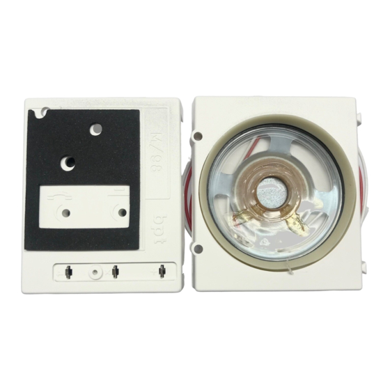
GRUPPO FONICO AZ/98
Collegamento connettore CN1
CN1 in posizione 1 (fig. 1): il grup-
po fonico é utilizzabile nei posti
esterni serie VZF in impianti video-
citofonici sistema 200, e nei posti
esterni serie Z e ZC in impianti
citofonici sistema 200.
CN1 in posizione 2 (fig. 1): il grup-
po fonico é utilizzabile nei posti
esterni serie VZ, VZC (in sostituzio-
ne del mod. AZ/95.
01
sostituzione del mod. AZ/96F) in
impianti videocitofonici sistema
100, e nei posti esterni serie Z e ZC
(in sostituzione del mod. AZ/95.
1
in impianti citofonici sistema 100.
Ponticello SW1
Negli impianti con citofoni a viva-
voce e negli impianti 1 + n é
necessario inserire il ponticello
SW1 (fig. 1).
Regolazione dei volumi
per impianti citofonici
P1: potenziometro di regolazione
audio al derivato interno (fig. 2).
P2: potenziometro di regolazione
audio al posto esterno (fig. 2).
La regolazione dovrà essere ese-
guita in modo tale che i livelli audio
siano ottimizzati, evitando di pro-
vocare l'effetto Larsen.
2
AVVERTENZE
PER L'INSTALLATORE
Con il gruppo fonico AZ/98 il
potenziometro P1 (regolazione del
volume al posto esterno) negli ali-
mentatori E/300Q, E/305S, E/310,
E/320 non va utilizzato.
Regolare questo potenziometro
nella posizione intermedia (come
fornito dalla BPT) per eliminare
eventuali disturbi nella linea audio
al posto esterno.
Caratteristiche tecniche
• Temperatura di funzionamento:
da -15 °C a +50 °C.
Altoparlante L/98
• Impedenza d'ingresso:
22 Ohm (AZ/95-AZ/96F)
800 Ohm (AZ/98).
• Potenza: 0,2W.
Microfono M/98
• Alimentazione: 11Vcc.
• Assorbimento: 50mA max. (10mA
a riposo).
INSTALLATION
GB
INSTRUCTIONS
AZ/98 PHONIC GROUP
Connecting CN1 connector
CN1 in position 1 (fig. 1): the pho-
nic group can be used in VZF
series entry panels in video entry
systems 200, and in Z and ZC
series entry panels in audio entry
systems 200.
CN1 in position 2 (fig. 1): the pho-
nic group can be used in VZ, VZC
(replacing mod. AZ/95.
serie entry panels (replacing mod
mod. AZ/96F) in video entry
systems 100, and Z and ZC series
entry panels (replacing mod.
AZ/95.
) in audio entry systems
01
100.
SW1 jumper
In installation with twin-channel
receivers and 1 + n systems, SW1
jumper must be inserted, figure 1.
Volume adjustment
for audio entry systems
P1: potentiometer for adjusting volu-
me at internal handset, figure 2.
P2: potentiometer for adjusting volu-
me at entry panel, figure 2.
Adjust the volume to give best
results without feedback.
) e VZF (in
WARNING FOR THE INSTALLER
With the AZ/98 the potentiometer
P1 (volume adjusting at entry
panel) in power suppliers E/300Q,
)
01
E/305S, E/310, E/320 is not used.
Adjust this potentiometer in the
intermediate position (as supplied
from BPT) to eventually eliminate
audio interferences in the external
panel.
Technical features
• Working temperature range:
from -15 °C to +50 °C.
Loudspeaker L/98
• Imput impedance:
22 Ohm (AZ/95-AZ/96F)
800 Ohm (AZ/98).
• Rated power: 0.2W.
Microphone M/98
• Supply voltage: 11V DC.
• Current demand: 50mA max.
(10mA quiescent).
INSTALLATIONS-
D
ANLEITUNG
LAUTSPRECHER- UND
MIKROFONSATZ AZ/98
Anschluß des Verbinders CN1
CN1 in Position 1 (Abb. 1):
Lautsprecher- und Mikrofonsatz für
Außenstationen der Serie VZF in
Video - Türsprechanlagen System
200 und für Außenstationen der
Serie Z und ZC in Haussprech-
anlagen System 200.
CN1 in Position 2 (Abb. 1):
Lautsprecher- und Mikrofonsatz für
Außenstationen der Serie VZ, VZC
(statt Mod. AZ/95.
(statt Mod. AZ/96F) in Video -
Türsprechanlagen System 100,
) and VZF
01
) und VZF
01
1
Publicidad

Resumen de contenidos para Bpt AZ/98
- Página 1 • Current demand: 50mA max. vocare l’effetto Larsen. (10mA quiescent). AVVERTENZE PER L’INSTALLATORE Con il gruppo fonico AZ/98 il potenziometro P1 (regolazione del volume al posto esterno) negli ali- INSTALLATIONS- mentatori E/300Q, E/305S, E/310, ANLEITUNG E/320 non va utilizzato.
- Página 2 POUR L’INSTALLATEUR die Sprechgarnitur (Abb.2). • Alimentação: 11Vcc. metro en la posición intermedia Avec le groupe phonique AZ/98 il P2: Klangregler-Potentiometer für • Absorção: 50mA max. (10mA em (como lo entrega BPT). ne faut pas utiliser le potentiomè- die Außenstation (Abb.2).


