Tabla de contenido
Publicidad
Idiomas disponibles
Idiomas disponibles
Enlaces rápidos
Thermo
TCLE, TJRE, TERE, TIRE, THRE
General information and technical data
• Refrigerants: see nameplate
• Evaporating Temperature Range:
a) for valves with pressure limitation (MOP): see
nameplate
b) for valves without pressure limitation:
+30° C to -45° C
• Max. Working Pressure PS: 31 bar
• Safe Working Temperature: 80° C
• Marking:
!
Safety instructions
• Read
installation
instruction
Failure to comply can result in device failure,
system damage or personal injury.
• It is intended for use by persons having the
appropriate
knowledge
and
opening any system make sure pressure in
system
is
brought
to
and
atmospheric
pressure.
Do
refrigerant into the atmosphere.
• Do not use on service conditions or fluids not
specifically cataloged, without prior approval of
Alco Controls.
Installation (Fig. 1)
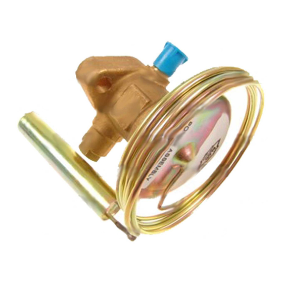
1 Power Assembly
7 Body Flange
2 Remote Bulb
3 External Equalizer
8 Seat Gasket
Connection
9 Body Flange
4 Seal Cap
10 Cap Screws
5 Body Flange Gasket
11 Lugged Spring
6 Cage Assembly
1. Valves may be installed in any position, but
should be located as close as possible to
distributor or evaporator inlet.
T_S__65022__R05
Installation Instructions
Installation Instructions
®
Expansion Valves
Expansion Valves
TJRE, TERE, TIRE, THRE
2. Install line connections to valve so its flow
Install line connections to valve so its flow
arrow corresponds to flow direction on flange.
arrow corresponds to flow direction on flange.
On valves with solder connections remove cap
On valves with solder connections remove cap
screws, power assembly, cage assembly and
screws, power assembly, cage assembly and
gaskets prior to brazing.
gaskets prior to brazing.
3. Assemble valve after brazing, acc
Assemble valve after brazing, according to Fig
1, making sure that lugs of spring carrier line up
1, making sure that lugs of spring carrier line up
with slots inside power assembly.
with slots inside power assembly.
4. Tighten
Tighten
specification 35 Nm.
specification 35 Nm. Overtorqueing may result
in valve body damage.
in valve body damage.
5. Attach remote bulb to suction line as close to
Attach remote bulb to suction line as close to
evaporator outlet as possible in a horizontal run
evaporator outlet as possible in a horizontal run
and fix it, normally at the 4 or 8 o'clock
and fix it, normally at the 4 or 8 o'clock
thoroughly.
position. Clean surface of suction line before.
position. Clean surface of suction line before.
6. Connect one end of external
Connect one end of external equalizer line (OD
= 6 mm = ¼ inch) to valve. Connect other end
= 6 mm = ¼ inch) to valve. Connect other end
to suction line slightly downstream from remote
to suction line slightl
skill.
Before
bulb location and position it so that it cannot
bulb location and position it so that it cannot
syphon oil from the suction line.
syphon oil from the suction line.
remains
at
7. Check for leaks, sufficient system refrigerant
Check for leaks, sufficient system refrigerant
not
leak any
and be sure no flash gas is present.
and be sure no flash gas is present.
Superheat Adjustment
Superheat Adjustment (Fig. 2)
ALCO Thermo
ALCO Thermo
preset for optimum superheat settings. This setting
preset for optimum superheat settings. This setting
should be modified only if absolutely necessary. The
should be modified only if absolutely necessary. The
readjustment should be at the lowest expected
readjustment should be at the lowest expected
evaporating temperature:
evaporating temperature:
Gasket
1. Remove seal cap (1) on side of valve.
Remove seal cap (1) on side of valve.
2. Turn adjusting stem clockwise to i
Turn adjusting stem clockwise to increase
superheat and counter-clockwise to decrease it.
superheat and counter
Allen key X 99999 (2).
Allen key X 99999 (2).
3. Reinstall seal cap. Wait 20 minutes before
Reinstall seal cap. Wait 20 minutes before
Carrier
further adjustments.
further adjustments.
4. If refrigerant escapes use allen key X99999 (3)
If refrigerant escapes use allen key X99999 (3)
to fix spindle gasket.
to fix spindle gasket.
Replacement for 04
placement for 04
Emerson Climate Technologies GmbH
Emerson Climate Technologies GmbH
GB
Holzhauser Str. 180 - D-13509 Berlin
www.emersonclimate.eu
cap
cap
screws
screws
evenly
evenly
to
to
torque
torque
®
-Expansion Valves are factory
Date: 20.06.2013
13509 Berlin
Germany
Pressure
Pressure
Evaporating temperature °C
Valve
Refri- changes
changes +10
0
Series gerant per turn
per turn
Static superheat changes
(bar)
(bar)
per turn of stem (K)
R 134a
0,05
0,05
0,4
0,5
R 22
0,05
0,05
0,3
0,3
TCLE R 404A
0,05
0,05
0,2
0,3
R 407C
0,05
0,05
0,2
0,3
R 507
0,05
0,05
0,2
0,3
TJRE R 134a
0,038
0,038
0,3
0,4
TERE, R 22
0,038
0,038
0,2
0,3
TIRE, R 404A
0,038
0,038
0,2
0,2
THRE R 407C
0,038
0,038
0,2
0,2
R 507
0,038
0,038
0,2
0,2
Note
1. Foreign particles in Thermo
particles in Thermo
®
diaphragm failure, flooding or starving. Use of
diaphragm failure, flooding or starving. Use of
an ALCO Filter Drier is strongly recommended.
an ALCO Filter Drier is strongly recommended.
2. Protect valve against excessive vibrations as it
Protect valve against excessive vibrations as it
may result in bulb tubing breaking.
may result in bulb tubing breaking.
Leakage test:
After completion of installation, a test pressure must
After completion of instal
be carried out as follows:
be carried out as follows:
- According to EN378 for systems which must
According to EN378 for systems which must
comply with European pressure equipment directive
comply with European pressure equipment directive
97/23/EC
- To maximum working pressure of system for other
To maximum working pressure of system for other
applications
Warning:
- Failure to do so could
Failure to do so could result in loss of refrigerant
and personal injury.
and personal injury.
- The pressure test must be conducted by skilled
The pressure test must be conducted by skilled
persons with due respect regarding the danger
persons with due respect regarding the danger
related to pressure.
-10
-20
-30
-40
0,6
0,9
0,4
0,5
0,7
1,0
0,3
0,4
0,6
0,8
0,4
0,6
0,3
0,4
0,5
0,7
0,5
0,7
0,3
0,4
0,5
0,7
0,3
0,3
0,5
0,6
0,3
0,4
0,2
0,3
0,4
0,5
-Valve may cause
PCN 862157
Publicidad
Tabla de contenido

Manuales relacionados para Emerson Thermo TCLE


Resumen de contenidos para Emerson Thermo TCLE
- Página 1 Installation Instructions Installation Instructions Emerson Climate Technologies GmbH Emerson Climate Technologies GmbH ® Thermo Expansion Valves Expansion Valves Holzhauser Str. 180 - D-13509 Berlin 13509 Berlin Germany TCLE, TJRE, TERE, TIRE, THRE TJRE, TERE, TIRE, THRE www.emersonclimate.eu General information and technical data 2.
-
Página 2: Sicherheitshinweise
Einbauanleitung Emerson Climate Technologies GmbH ® Thermo -Expansionsventile Holzhauser Str. 180 - D-13509 Berlin Germany TCLE, TJRE, TERE, TIRE, THRE www.emersonclimate.eu Beschreibung und technische Daten Oberteil Ventileinsatz 3. Hutmutter wieder aufsetzen. Vor einer weiteren • Kältemittel: siehe Typschild Dichtungen entfernen. -
Página 3: Détendeur Thermostatique
Instructions d’Installation Emerson Climate Technologies GmbH Détendeur thermostatique Holzhauser Str. 180 - D-13509 Berlin Germany TCLE, TJRE, TERE, TIRE, THRE www.emersonclimate.eu Données techniques Variation Temp. d'évaporation ° C 3. Détendeur à braser, démontez train Série Fluide de press. +10 • Réfrigérants: voir plaque indicatrice thermostatique, le cage et les joints avant de par rotat. -
Página 4: Válvula De Expansion Termostatica
Instrucciones de Instalacion Emerson Climate Technologies GmbH Válvula de Expansion Termostatica Holzhauser Str. 180 - D-13509 Berlin Germany TCLE, TJRE, TERE, TIRE, THRE www.emersonclimate.eu Datos técnicos de fijación, el elmento termostático, el conjunto 4. Si se produce una fuga del refrigerante utilice •... -
Página 5: Dati Tecnici
Istruzioni per l’installazione Emerson Climate Technologies GmbH Valvola d’espansione termostatica Holzhauser Str. 180 - D-13509 Berlin Germany TCLE, TJRE, TERE, TIRE, THRE www.emersonclimate.eu che non vi siano altre parti montate oltre allo 4. Per evitare perdite di refrigerante, utilizzate Dati tecnici zoccolo. - Página 6 Installatievoorschrift Emerson Climate Technologies GmbH ® Thermo -Expansieventielen Holzhauser Str. 180 - D-13509 Berlin Germany TCLE, TJRE, TERE, TIRE, THRE www.emersonclimate.eu 3. Na solderen het ventiel weer in elkaar zetten Toepassing Verdampingstemp. ° C Drukverand. overeenkomstig de afbeelding van Fig. 1.
- Página 7 Emerson Climate Technologies GmbH Emerson Climate Technologies GmbH Инструкция по установке установке ТРВ® серий Holzhauser Str. 180 - D-13509 Berlin 13509 Berlin Germany TCLE, TJRE, TERE, TIRE, THRE TJRE, TERE, TIRE, THRE www.emersonclimate.eu 3. Соберите Технические характеристики Соберите вентиль после...
- Página 8 Emerson Climate Technologies GmbH Emerson Climate Technologies GmbH TCLE, TJRE, TERE, TIRE, THRE TCLE, TJRE, TERE, TIRE, THRE Holzhauser Str. 180 - D-13509 Berlin 13509 Berlin Germany www.emersonclimate.eu Fig. 1: Fig. 2: > 10 Nm < 15 Nm < 15 Nm...