Tabla de contenido
Publicidad
Idiomas disponibles
Idiomas disponibles
Enlaces rápidos
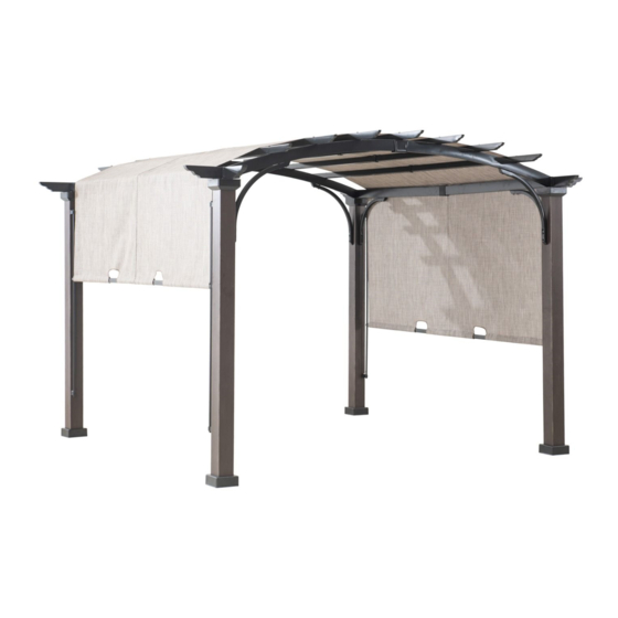
11X11' Pergola
Item No.: 800925
Model No.: A106000904
Our clear, easy-to-follow, step-by-step instructions will guide you through the
project from start to finish. The final product will be a quality piece that will go
together smoothly and give years of enjoyment.
Do NOT assemble this item alone for safety. Two people are necessary.
Publicidad
Tabla de contenido

Resumen de contenidos para Sunjoy A106000904
- Página 1 11X11' Pergola Item No.: 800925 Model No.: A106000904 Our clear, easy-to-follow, step-by-step instructions will guide you through the project from start to finish. The final product will be a quality piece that will go together smoothly and give years of enjoyment.
-
Página 2: Care & Maintenance
IMPORTANT: 1. Keep all children and pets away from assembly area. Children and pets should be supervised while gazebo is being assembled. 2. The assembled gazebo should be located at least 6 feet (2 m) from any obstruction such as fence, garage, house, overhanging branches, laundry lines or electrical wires. -
Página 3: Parts List
Parts List: Label Part Number Description Image Post 1 P000200068 Post 2 P000200069 Top Arc P000600159 Beam Top Beam 1 P000600215 Top Beam 2 P000600216 Top Beam 3 P000600217 Connector 1 P000500140 Connector 2 P000500165 Beam P005600011 Decoration Post P000300101 Decoration Support Bar 1 P005000031... -
Página 4: Hardware List
Ferrule 1 P002200007 Ferrule 2 P002200008 Base Cover P006100029 Base P000100035 Hardware List: Description Part Number Label Image H010020012 M6 x 20 mm Short Bolt H050030001 M6 Washer H010020025 M6 x 60mm Middle Bolt H040010004 M6 Nut H010020021 M6 x 70 mm Long Bolt H070010003 Φ8 x180 mm Stake H010110016... - Página 5 Fig.1: Insert the posts (A3/A4) into the base covers (P), then attach the bases (Q) to the posts (A3/A4) using bolts (AA) and, washers (BB/LL). Tighten with wrench (ZZ). Fig.2: Place the post decoration (G3) onto the top of the posts (A3/A4). Fig.3-1: Insert the connectors 1 (E1) to the beams 1(C), secure with bolts (AA) and washers (BB/LL), tighten with wrench (ZZ).
- Página 6 Fig.5-1: Insert the connectors 2 (F1) to the top arc beams (B), secure with bolts (AA) and washers (BB/LL), tighten with wrench (ZZ). Fig.5-2: Attach the ferrule 1 (O1) to the assembled top arc beams (B) and connector 2 (F1). Fig.5-3: Attach the other top arc beams (B) to the top arc beam assemblies (B/F1/O1) and secure with bolts (AA) and washers (BB/LL), tighten with wrench (ZZ).
- Página 7 Fig.8: Connect top beams 3 (D3) with top beams 2 (D2), then secure with bolts (JJ) and washers (BB), tighten with Phillips screwdriver (not included) Fig.9: Attach the assembled top beams (D2/D3) to the assembled top arc beams (B) using bolts (EE) and washers (BB).
- Página 8 Pérgola 3,3x3,3 M Artículo No.: 800925 Modelo No.: A106000904 Nuestras instrucciones, claras, fáciles de seguir, y por pasos le guiaranán por el proyecto desde el principio hasta el final. El producto terminado será una pieza de calidad que se ensamblará fácilmente y del que podrá gozar por muchos años.
-
Página 9: Cuidado Y Mantenimiento
IMPORTANTE: 1. Mantenga a los niños y animales fuera de l área de ensamblaje. Los niños y mascotas deben estar bajo vigilancia durante el ensamblaje del toldo. 2. El Gazebo montado se debe colocar a una distancia de más de 6 pies (2m) de cualquier obstrucción tal como verjas, garaje, casa, ramas colgantes, cuerda para tender o cables eléctricos. -
Página 10: Lista De Piezas
Lista de piezas: Idenificación Part Number Descripción Cantidad Imágen Poste 1 P000200068 Poste 2 P000200069 Arco superior P000600159 de la viga Viga superior P000600215 Viga superior P000600216 Viga superior P000600217 Conector 1 P000500140 Conector 2 P000500165 Decoración P005600011 de la viga P000300101 decoración Barra de... -
Página 11: Lista De Piezas De Ferretería
Casquillo 1 P002200007 Casquillo 2 P002200008 Cobertor de P006100029 la base Base P000100035 Lista de piezas de ferretería: Identificación Part Number Descripción Cantidad imagen H010020012 Perno corto M6 x 20 mm H050030001 Arandela M6 Perno mediano M6 x H010020025 60mm H040010004 Tuerca M6 H010020021... - Página 12 Fig.1: Inserte los postes (A3, A4) en los cobertores de la base (P), luego fije las bases (Q) a los postes (A3, A4) con pernos (AA) y arandelas (BB,LL). Apriete con la llave inglesa(ZZ) Fig.2: Fije las decoraciones para poste (G3) a los postes (A3, A4) con pernos (CC). Fig.3-1: Inserte los conectores 1 (E1) en las vigas superiores 1 (C), asegure con pernos (AA) y arandelas (BB,LL), apriete con la llave inglesa (ZZ).
- Página 13 Fig.5-1: Inserte el conectores 2 (F1) a las vigas del arco superior (B) con pernos (AA) y arandelas (BB,LL), apriete con la llave inglesa (ZZ) Fig.5-2:Fije las casquillo 1 (O2) a las vigas del arco superiors ensambladas (B) y conectores 2 (F1). Fig.5-3: Fije las vigas del arco superiors (B) a las arco superior de ensambladas (B,F1,O1) con pernos (AA) y arandelas (BB,LL).
- Página 14 Fig.8: Conecte las vigas superiores 3 (D3) con las vigas superiores 2 (D2), luego asegure con pernos (JJ) y arandelas (BB). Fig.9: Fije las vigas superiores ensambladas (D2, D3) a las vigas del arco superior ensambladas (B) con pernos (EE) y arandelas (BB) , apriete con la llave inglesa (ZZ). Fig.10: Inserte los tubos de tela 1 (L3) a los tubos de tela 2 (L4), luego asegure con pernos (JJ) y arandelas (BB,LL).

