
Manuales relacionados para EAS ELECTRIC E190WHF

Resumen de contenidos para EAS ELECTRIC E190WHF
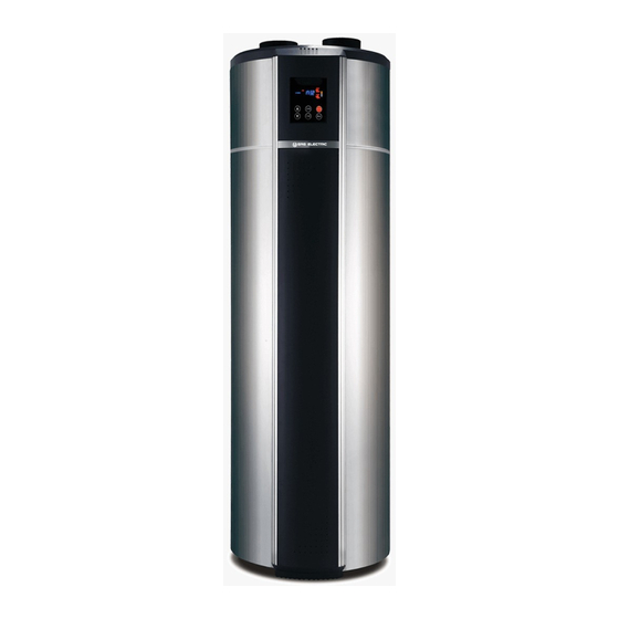
- Página 1 ACUMULADOR AEROTÉRMICO ACS HEAT PUMP WATER HEATER E190WHF MANUAL DE INSTRUCCIONES INSTRUCTION MANUAL...
-
Página 2: Tabla De Contenido
CONTENIDOS A. OBSERVACIONES IMPORTANTES--------------------------------------------------------------------------------- 1 B. DESCRIPCIÓN DEL PRODUCTO------------------------------------------------------------------------------------ 2 C. INSTRUCCIONES DE INSTALACIÓN---------------------------------------------------------------------------- 3-5 D. INSTRUCCIONES DEL PANEL DE FUNCIONAMIENTO-------------------------------------------------6-10 E. MANTENIMIENTO Y SERVICIO -------------------------------------------------------------------------------- 11-12 F. DIAGRAMA DE CIRCUITO DE LA UNIDAD ------------------------------------------------------------- 13 G. LISTA ANEXA------------------------------------------------------------------------------------------------------------ 14 ADVERTENCIA: 1. -
Página 3: Observaciones Importantes
A. Observaciones importantes Gracias por elegir nuestros productos. Antes de la instalación, se recomienda leer este manual instrucción. Este manual incluye la información de instalación, depuración, funcionamiento y mantenimiento de los productos. Cada unidad ha pasado estrictamente la prueba de calidad para garantizar la seguridad y la alta eficiencia en su funcionamiento. -
Página 4: Descripción Del Producto
B. Descripción del producto Aspecto de la unidad (exterior): Cubierta superior Pantalla Cubierta superior Barra de decoración Orificio de cableado Línea eléctrica Panel eléctrico Tubería de ventilación Compresor Ventilador de ventilación Evaporador Chasis principal Barra de decoración izda/dcha Orificio de drenaje del condensado Panel decorativo Salida de agua caliente Orificio del ánodo de magnesio... -
Página 5: Instrucciones De Instalación
C. Instrucciones de instalación Nota: 1. Esta unidad de bomba de calor se puede instalar en la galería, pasillo u otro lugar donde sea fácil de instalar y esté estable. La entrada y salida de aire están en el lado superior por lo que la unidad principal no debe colocarse al aire libre. - Página 6 C. Instrucciones de instalación 8. Cuando la unidad funcione, colóquela en un lugar bien ventilado y sin bloquear la ventilación de aire, de modo que la máquina pueda inhalar y extraer suficiente aire para hacerfuncionar la función de suministro de agua caliente. 9.
- Página 7 C. Instrucciones de instalación Diagrama de instalación Salida de aire Entrada de aire Tubería de ventilación CLOCK ON/OFF TIMER MODE Salida de agua caliente Drenaje de agua condensada (Uso de agua caliente) Válvula de seguridad Tubería de drenaje Entrada de agua en circulación caliente Salida de agua en circulación caliente...
-
Página 8: Instrucciones Del Panel De Funcionamiento
D. Instrucciones del panel de funcionamiento 1. Panel - Funcionamiento:... - Página 9 D. Instrucciones del panel de funcionamiento 2. Panel - Pantalla: Ajuste temperatura Temperatura alta Alarma Resistencia de apoyo Estado HTG: Heating (calentamiento) DEF: Defrost (descongtelación) WARM: Keep warm (Mantiene caliente) Modo de funcionamiento Ajuste de hora Hora Temporizador ON Temporizador OFF Periodos temporizador Temperatura agua Gradiente de temperatura...
- Página 10 D. Instrucciones del panel de funcionamiento 3. Ajuste de parámetros: Presione el botón "MODE" durante 5 segundos; ingrese el estado de configuración de parámetros, los códigos de parámetros principales son los que se muestra a continuación: Observaciones Nombre del parámetro Tipo Código Rango de ajuste Ajuste de fábrica Unidad...
- Página 11 consulta de apertura EEV 0–480 Modo de control EEV 0–2 Válvula de Ajuste manual apertura EEV 100–480 expansión Ajuste grado de sobrecalentamiento EEV -15–15 electrónica Ajuste temp. descarga EEV 85–110 (EEV) Temp. retorno gas “OFF” significa que no hay contraseña Contraseña 4321 Ajustes del...
- Página 12 D. Instrucciones del panel de funcionamiento 4. Manejo de errores: Código de error Estado de error Razones Manejo del error Sensor de la temperatura del 1. Compruebe la conexión del sensor de agua de circuito abierto o Alarma del sensor termal temperatura del agua.
-
Página 13: Mantenimiento Y Servicio
E. Mantenimiento y servicio Examen antes de la prueba 1. Verifique que el tanque de agua esté lleno y abra el grifo de salida de agua hasta que salga. 2. Verifique que la presión del agua sea normal (0.15Mpa ~ 0.7Mpa). 3. - Página 14 E. Mantenimiento y servicio Desmontaje de la unidad principal Si desea verificar y mantener las partes principales superiores de la unidad y debe desarmar la cubierta de la unidad, siga los pasos a continuación (Fig. 5, 6) para el proceso. CLOCK ON/OFF TIMER...
-
Página 15: Diagrama De Circuito De La Unidad
F. Diagrama de circuito de la unidad El siguiente es un diagrama de circuito de la unidad (para referencia del usuario); La conexión de la unidad debe ser como el diagrama de circuito / cableado de la máquina. Bomba de calor con resistencia de apoyo auxiliar: SENSOR TEMP. -
Página 16: Lista Anexa
G. Lista anexa ITEM Nombre Especificación Cantidad Observación Válvula de seguridad Manual En base a la norma europea del 2012/19/UE de residuos de aparatos eléctricos y electrónicos (RAEE), los electrodomésticos no pueden ser arrojados en los contenedores municipales habituales; tienen que ser recogidos selectivamente para optimizar la recuperación y reciclado de los componentes y materiales que los constituyan, y reducir el impacto en la salud humana y el medio ambiente. - Página 17 Requisitos de calidad del agua en el circuito La calidad del agua debe cumplir los estándares de la Directiva Europea 98/83 CE y los criterios indicados en la Norma UNE 112.076. La calidad del agua se debe analizar antes de su uso; para evaluar criterios como el valor de pH, la conductividad, la concentración de iones de cloruro (Cl-), la concentración de iones de sulfuro (S2-), etc.
- Página 18 CONDICIONES DE LA GARANTÍA COMERCIAL Este producto tiene una garantía de reparación de dos años a partir de la fecha de venta, contra todo defecto de funcionamiento proveniente de la fabricación, incluyendo mano de obra y piezas de recambio, y cinco años de garantía en el compresor (solo componente).
- Página 19 Daños en fusibles, lamas, focos, flujostato de caudal, filtros y otros elementos derivados del desgaste normal debido a la operación del equipo. Las averías que tengan su origen o sean consecuencia directa o indirecta de: contacto con líquidos, productos químicos y otras sustancias, así como de condiciones derivadas clima...
- Página 20 CONTENTS A. IMPORTANT REMARKS -----------------------------------------------------------------------------------------------1 B. DESCRIPTION OF HEAT PUMP ------------------------------------------------------------------------------------2 C. INSTALLATION INSTRUCTION ----------------------------------------------------------------------------------- 3-5 D. OPERATION PANEL INSTRUCTION -------------------------------------------------------------------------- 6-10 E. MAINTENANCE AND SERVICE ------------------------------------------------------------------------------- 11-12 F. UNIT CIRCUIT DIAGRAM -------------------------------------------------------------------------------------------- 13 G. ANNEX LIST ------------------------------------------------------------------------------------------------------------ 14 WARNING: 1.
-
Página 21: Important Remarks
A. Important remarks Thank you for choosing our products. Before installation, it is strongly recommended to read this instruction firstly. This manual includes the information of installation, debugging, running and maintenance of the products. Every unit of products has passed strictly test to ensure safety and high efficiency operation. ... -
Página 22: Description Of Heat Pump
B. Description of heat pump Unit constructions (outside): Top Cover Screen Panel Upper Cover Decoration Bar Wiring Hole Power Line Electric Board Vent Pipe Compressor Ventilation Fan Evaporater Host Chassis Left/Right Decoration Bar Condensate Drain Hole Decoration Panel Hot Water Outlet Magnesium Anode Hole Safety Valve Hole Electric Heater Cover... -
Página 23: Installation Instruction
C. Installation instruction Note: 1. This heat pump unit can be installed at veranda, hallway or other place where is easy to install and stable. The air inlet & outlet are at the top side, main unit should not be placed at an open air. Avoid the rain or debris to enter the vents. - Página 24 C. Installation instruction 8. When unit operation, put the unit in a well-ventilated place and non-blocking the air vent, so that the machine can be able to inhale and exhaust enough air, to achieve hot water supply function. 9. There should be with drain around the system unit for drainage. And the surrounding should have enough space for maintenance.
- Página 25 C. Installation instruction Installation diagram: Air Outlet Air Inlet Vent Tube CLOCK ON/OFF TIMER MODE Hot Water Outlet Condensate water (Hot Water use ) drainage Safety Valve Drainage Pipe Heat Circulation water inlet Heat Circulation water outlet Three-port Valve Filter One-way Valve Water Inlet (Water Supply )
-
Página 26: Operation Panel Instruction
D. Operation panel instruction 1. Panel - Operation:... - Página 27 D. Operation panel instruction 2. Panel - Display: Set Temperature 设定水温显示 High Temperature 水温高温提示 Alarm 机器报警指示 Auxiliary Heater 辅电加热指示 Status 机器状态指示 HTG: Heating DEF: Defrost WARM: Keep warm Working Mode 工作模式指示 Time adjustment 调节时钟指示 Time 当前时间显示 Timer On 定时开显示 Timer Off 定时关显示...
- Página 28 D. Operation panel instruction 3. Parameter Setting: Press “MODE” button for 5 seconds; enter the Parameter setting status, the main parameter code as below sheet: Type Code Parameter Name Setting Range Factory Setting Unit Remark Setting temperature 5-70 °C Difference in Temp. 1 - 30 °C Determine Heat pump stop...
- Página 29 EEV opening query 0–480 EEV control mode 0–2 Electronic Manually set EEV opening 100–480 expansion Set EEV superheat degree -15–15 valve(EEV) Set EEV discharge temp 85–110 Return gas temp. “OFF” means no password. Password 4321 System Set “0000” to 0001 -- 9999 clear password.
- Página 30 4. Error Handling: ERROR ERROR STATUS REASONS ERROR HANDLING CODE 1. Check the water temp. sensor Thermal sensor Water temp. sensor open connection. alarm circuit or short circuit. 2. Change the water temp. sensor. 1. Check the condenser coil temp. Condenser coil Condenser coil temp.sensor sensor connection.
-
Página 31: Maintenance And Service
E. Maintenance and service Examination before trial run 1. Check the water tank is filled with water, and open the water outlet tap till water flow out. 2. Check the water pressure is normal (0.15Mpa~0.7Mpa). 3. Check the air inlet or outlet is well connected; and the air outlet pipe heat insulation is completed. 4. - Página 32 E. Maintenance and service Heat Pump main unit disassembly If want to check and maintain the top main parts of the unit, should disassembly the cover of the unit, follow the below steps (Fig.5, 6) to process. CLOCK ON/OFF TIMER MODE (Fig.5) (Fig.6)
-
Página 33: Unit Circuit Diagram
F. Unit circuit diagram The following is a unit circuit diagram (for user’s reference); the unit practical connection should be as the circuit /wiring diagram on the machine. 1). Heat pump WITH auxiliary electric heater: COIL TEMP.SENSOR AMBIENT TEMP.SENSOR WATER TEMP.SENSOR EXHAUST TEMP.SENSOR OPERATION PANEL RETURN GAS TEMP. -
Página 34: Annex List
G. Annex list ITEM NAME SPECIFICATION QUANTITY REMARK Safety valve Manual The european directive to 2012/19 /EU on wasted electrical and electronic equipments (WEEE), requires that household electrical appliances must not be disposed of in the normal unsorted municipal waste stream. appliances must be collected separately in order to optimize the recovery and recycling of the materials they contain, and reduce the impact on human health and the environment. - Página 35 Water quality requirements on the circuit Water quality must meet the standards of European Directive 98/83 EC and the criteria set out in UNE 112.076. Water quality should be analysed before use; to evaluate criteria such as concentration, pH value, conductivity, chloride ion concentration (Cl-), sulfide ion concentration (S2-), etc.
- Página 36 COMMERCIAL GUARANTEE CONDITIONS FOR AIR CONDITIONING This product has a two-year repair guarantee from the date of sale, against all manufacturing malfunctions, including repairwork and replacement parts, and a five-year guarantee on the compressor (component only). To justify the purchase date, it will be mandatory to present the end user's invoice or purchase receipt and the installation company data.
- Página 37 15. Damage to fuses, blades, lamps, flow switch, filters and other elements derived from normal wear and tear due to the operation of the equipment. 16. Faults that have their origin or are a direct or indirect consequence of: contact with liquids, chemicals and other substances, as well as conditions derived from the climate or the environment: earthquakes, fires, floods, excessive heat or any other external force , such as insects, rodents and other animals that may have access to...