
Manuales relacionados para Quick DP Serie


Resumen de contenidos para Quick DP Serie
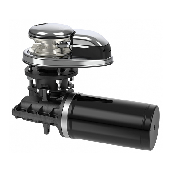
- Página 1 Serie DP REV 000A MOLINETES DEL ANCLA VERTICALES DP1_P 300 500 DP2_P 300 500 700 1000 DP3_P 700 1000 DP3 1500 ES - MANUAL DE INSTALACIÓN Y USO...
-
Página 2: Información Sobre El Producto
Serie DP 1 - Información sobre el producto ANTES DE UTILIZAR EL MOLINETE LEER CON ATENCIÓN EL PRESENTE MANUAL DE INSTRUCCIONES. EN CASO DE DUDA CONSULTAR CON EL CONCESIONARIO VENDEDOR QUICK ® QUICK ® SE RESERVA EL DERECHO DE APORTAR MODIFICACIONES EN LAS CARACTERÍSTICAS TÉCNICAS DEL APARATO Y EN EL CONTENIDO DE ESTE MANUAL SIN OBLIGACIÓN DE AVISAR PREVIAMENTE. - Página 3 8 mm 5/6” Cadena soportada DIN 766 DIN 766 DIN 766 Cuerda soportada* 1/2” 1/2” 1/2” 1/2” 1/2” (*) Para los códigos de los barbotenes consultar el despiece de pág. 17. MANUAL DE INSTALACIÓN Y USO QUICK SERIE DP - REV000A...
- Página 4 Cuerda soportada* 1/2” (12,7 mm) - 9/16” (14,2 mm) - 5/8” (15,8 mm) 5/8” (15,8 mm) *Los valores indicados en la tabla se refieren a una combinación de cuerda y cadena según el sistema Quick , no garantizamos ® el funcionamiento correcto con tipos distintos de anchor-rode.
-
Página 5: Suministro De Serie Y Material Incluido
Serie DP 3 - Introducción ANTES DE UTILIZAR EL PRODUCTO, LEER ATENTAMENTE EL PRESENTE MANUAL DE USO; EN CASO DE DUDAS CONSULTAR CON EL DISTRIBUIDOR QUICK®. 3.0 - Notas importantes El presente manual contiene símbolos de Advertencia y/o de Atención importantes para la seguridad. -
Página 6: Requisitos Para La Instalación
• La ensambladura entre la cuerda y la cadena debe ser de dimensiones reducidas para poder desplazarse fácilmente dentro del perfil del barbotén. Ante cualquier inconveniente o necesidad contactar con el servicio de asistencia Quick®. • Para más seguridad, si un mando se daña, se recomienda instalar al menos dos mandos para el manejo del molinete. -
Página 7: Procedimientos De Montaje
Fijar el molinete apretando las tuercas en los prisioneros de bloqueo. Conectar los cables de alimentación que proceden del molinete al teleinvertidor. ESPÁRRAGO JUNTA JUNTA BRIDA REDUCTOR TOP ARANDELA 45° GROWER TUERCA PAINT 8÷10 MANUAL DE INSTALACIÓN Y USO QUICK SERIE DP - REV000A... -
Página 8: Instalación
Motorreductor 300/500W Motorreductor 700W/1000W Motorreductor 1500W 90° 90° 90° 45° 45° 45° 90° 45° 90° 90° 45° 90° 45° 90° 90° 90° 45° 90° 45° 45° 90° 45° 90° MANUAL DE INSTALACIÓN Y USO QUICK SERIE DP - REV000A... - Página 9 INTERRUPTOR 2A (24V) MAGNETO- HIDRÁULICO WCB (VÉASE LA TABLA DE PÁG. 4) CAJA DE TELEINVERTIDORES T6415-12 (12V) T6415-24 (24V) L = L1 + L2 + L3 + L4 + L5 MANUAL DE INSTALACIÓN Y USO QUICK SERIE DP - REV000A...
-
Página 10: Esquema De Conexión
PULSADORES DE PIE 900U Y 900D MOTOR NEGRO MARRÓN AZUL FUSIBLE 4A (12V) 2A (24V) CAJA DE TELERRUPTORES T6315-12 (12V) T6315-24 (24V) L = L1 + L2 + L3 + L4 MANUAL DE INSTALACIÓN Y USO QUICK SERIE DP - REV000A... -
Página 11: Advertencias Importantes
• NO activar eléctricamente el molinete del ancla con la palanca introducida en la campana o en la tapa del barbotén. • Quick® recomienda utilizar una protección tipo fusible/magnetotérmico/magnetohidráulico de potencia adecuada, según el motor utilizado, para proteger el motor de sobrecalentamientos o cortocircuitos. -
Página 12: Solución De Problemas
Los molinetes de ancla Quick® se fabrican con materiales resistentes al ambiente marino: de todos modos, es indispensable, quitar periódicamente los depósitos de sal que se forman en las superficies externas para evitar corrosiones y, por consiguiente, daños al aparato. - Página 13 SEPARA-CADENA DP1 ACERO INOXIDABLE CHAVETA PASADOR Cono embrague DP1 TORNILLO BARBOTÉN 500W TAPA BASE DP1 ACERO INOXIDABLE RETÉN APLICACIÓN TAPA DP1 PLÁSTICO ANILLO ELÁSTICO INTERNO TUERCA ANILLO ELÁSTICO EXTERNO TUERCA MANUAL DE INSTALACIÓN Y USO QUICK SERIE DP - REV000A...
-
Página 14: Lista Componentes Dp2
TORNILLO APLICACIÓN PASA-CADENA DP2 PLÁSTICO ARANDELA ARANDELA MOLDEADA TORNILLO ARANDELA DENTADA RETÉN MUELLE TENSOR CUERDA TUERCA ANILLO ELÁSTICO INTERNO PALANCA TENSORA CUERDA DP2 ANILLO ELÁSTICO EXTERNO PASADOR CILÍNDRICO COJINETE TORNILLO MANUAL DE INSTALACIÓN Y USO QUICK SERIE DP - REV000A... - Página 15 MUELLE TENSOR CUERDA JUNTA/PLANTILLA DPR TORNILLO PALANCA TENSORA CUERDA SENSOR ARANDELA MOLDEADA PASADOR CILÍNDRICO ESPÁRRAGO RETÉN TORNILLO ARANDELA ANILLO ELÁSTICO INTERNO TORNILLO ARANDELA DENTADA ANILLO ELÁSTICO EXTERNO TORNILLO TUERCA COJINETE TORNILLO MANUAL DE INSTALACIÓN Y USO QUICK SERIE DP - REV000A...
-
Página 16: Lista Componentes Motorreductores
JUNTA PLACA DE BORNES 700/1000W TUERCA AUTOBLOCANTE TAPA PLACA DE BORNES 700/1000W JUNTA TÓRICA TORNILLO CHAVETA JUNTA FONDO 700/1000W MOTOR 700W 12V TAPA FONDO 700/1000W MOTOR 1000W 12V PASACABLE MOTOR 700W 24V MANUAL DE INSTALACIÓN Y USO QUICK SERIE DP - REV000A... - Página 17 JUNTA PLACA DE BORNES ARANDELA TAPA PLACA DE BORNES TUERCA AUTOBLOCANTE TORNILLO JUNTA TÓRICA TORNILLO REDUCTOR - QUICK TG70 1500W JUNTA FONDO CHAVETA TAPA FONDO MOTOR 1500W 12V PASACABLE MOTOR 1500W 24V MANUAL DE INSTALACIÓN Y USO QUICK SERIE DP - REV000A...
-
Página 18: Piezas De Recambio
FVSSPSCDP200A00 OSP KIT PASA-CADENA DP2 24 - 25 - 29 - 30 - 32 FVSSGMSDCP05000 OSP CASQUILLO CAMPANA DP2 FVSSLVSDN000A00 OSP PALANCA MOLINETE RECTA FVSSLVSP00R2A00 OSP PALANCA MOLINETE CURVA R2 MANUAL DE INSTALACIÓN Y USO QUICK SERIE DP - REV000A... - Página 19 OSP MOTORREDUCTOR 1500W 12V QUICK de 1 a 15 FVSSR1524Q00A00 OSP MOTORREDUCTOR 1500W 24V QUICK FVSSM1512000A00 OSP MOTOR ELÉCTRICO MOLINETE 1500W 12V 2-3-4 de 6 a 15 FVSSM1524000A00 OSP MOTOR ELÉCTRICO MOLINETE 1500W 24V MANUAL DE INSTALACIÓN Y USO QUICK SERIE DP - REV000A...
-
Página 20: Dimensiones
355 (13 31/32) 385 (15 5/32) 69 (2 23/32) 78 (3 1/16) 78 (2 3/16) 92 (3 5/8) 61 (2 13/32) 68 (2 43/64) 68 (2 43/64) 82 (3 7/32) MANUAL DE INSTALACIÓN Y USO QUICK SERIE DP - REV000A... -
Página 21: Information About The Product
(5) On request, shafts and studs can be supplied for greater deck thicknesses. (6) Only on request. GYPSY (*) 6 mm 1/4” 1/4” Chain size DIN 766 (*) For gypsy codes, see the exploded drawing on page 16 QUICK DPSeries INSTALLATION AND USER’S MANUAL - REV000A... - Página 22 1/4” 8 mm 8 mm 5/6” Chain size DIN 766 DIN 766 DIN 766 Rope size* 1/2” 1/2” 1/2” 1/2” 1/2” (*) For gypsy codes, see the exploded drawing on page 17. QUICK DPSeries INSTALLATION AND USER’S MANUAL - REV000A...
- Página 23 Rope size* 1/2” (12.7 mm) - 9/16” (14.2 mm) - 5/8” (15.8 mm) 5/8” (15.8 mm) *The values in the table apply to the combination of rope and chain according to the Quick system, we do not guarantee the ®...
-
Página 24: Tools Required For Installation
•Control system via RRC radio (R02 - P02 - H02) DP Series 3 - Introduction BEFORE USING THE PRODUCT, PLEASE READ THIS USER’S MANUAL CAREFULLY. IF IN DOUBT, PLEASE CONSULT YOUR QUICK® DEALER. 3.0 - Important notes This manual features Warning and/or Caution symbols that are important for safety. -
Página 25: Installation Requirements
• The splice between the rope and the chain must be tightly woven for the rope to slide easily into the gypsy shape. For any problem or request, feel free to contact Quick® Technical Service. • For improved safety, we recommend installing at least two controls to operate the windlass in case one is damaged. -
Página 26: Installation Procedures
If this is not the case, compensate the difference appropriately (fig. B). A lack of parallelism could result in a loss of motor power. The deck thickness must be included among the figures listed in the table. In case of different thickness, please contact your Quick ® dealer. 5 mm (3/6”) C PEAK DEPTH AND BOW ROLLER HEIGHT There must be no obstacles to the passage of cables, rope and chain under deck (fig. 1C). - Página 27 It is possible to rotate the motorgearbox every 45° in relation to the base of the windlass. Possible motorgearbox positions: Motorgearbox 300/500W Motorgearbox 700/1000W Motorgearbox 1500W 90° 90° 90° 45° 45° 45° 90° 45° 90° 90° 45° 90° 45° 90° 90° 90° 45° 90° 45° 45° 90° 45° 90° QUICK DPSeries INSTALLATION AND USER’S MANUAL - REV000A...
-
Página 28: Wiring Diagram
FUSE 4A (12V) HYDRAULIC 2A (24V) MAGNETIC SWITCH WCB (SEE TABLE ON PAGE 4) REVERSING CONTACTOR BOX T6415-12 (12V) T6415-24 (24V) L = L1 + L2 + L3 + L4 + L5 QUICK DPSeries INSTALLATION AND USER’S MANUAL - REV000A... - Página 29 RRC R02 RECEIVER WINDLASS FOOT-OPERATED SWITCHES MOD. 900U E 900D MOTOR BLACK BROWN BLUE FUSE 4A (12V) 2A (24V) CONTACTOR BOX T6315-12 (12V) T6315-24 (24V) L = L1 + L2 + L3 + L4 QUICK DPSeries INSTALLATION AND USER’S MANUAL - REV000A...
-
Página 30: Important Cautions
• DO NOT operate the windlass by using the electrical power when the handle is inserted in the drum or into the gypsy cover. • Quick® recommends using a suitable power fuse/thermal-magnetic/hydraulic-magnetic protection for the motor used, to protect the motor from overheating or short circuits. -
Página 31: Product Disposal
Carefully remove the chain from the gypsy or the rope from the drum. Quick® windlasses are made of materials resistant to the marine environment: it is essential, in any case, to periodically remove salt deposits that form on the external surfaces to avoid corrosion and consequently damage to the device. -
Página 32: Spare Parts
OSP WINDLASS DRUM DP2 FVSSPSCDP200A00 OSP CHAIN PIPE KIT DP2 24 - 25 - 29 - 30 - 32 FVSSGMSDCP05000 OSP DRUM BUSH DP2 FVSSLVSDN000A00 OSP STRAIGHT WINDLASS LEVER FVSSLVSP00R2A00 OSP CURVED WINDLASS LEVER R2 QUICK DPSeries INSTALLATION AND USER’S MANUAL - REV000A... - Página 33 OSP GEARBOX 500W WINDLASS QUICK TG40 R1 1 - 2a - 3 - 4 - 12 FVSSMR0540HSB00 OSP GEARBOX 500W WINDLASS QUICK TG40 HS R1 1 - 2b - 3 - 4 - 12 FVSSR0312Q00B00 OSP MOTORGEARBOX 300W 12V QUICK R1...
- Página 34 340 (13 24/64) 355 (13 31/32) 385 (15 5/32) 69 (2 23/32) 78 (3 1/16) 78 (2 3/16) 92 (3 5/8) 61 (2 13/32) 68 (2 43/64) 68 (2 43/64) 82 (3 7/32) QUICK DPSeries INSTALLATION AND USER’S MANUAL - REV000A...