
Manuales relacionados para Bosch Rexroth VM310


Resumen de contenidos para Bosch Rexroth VM310
- Página 1 VM310 3 609 929 A96 (06.04) 3 Min Reset VM310 3 ~ 230 V L1, L2, L3 1 ~ 230 V 3 Min L1 … 230 V L2 … N > – 10mm...
- Página 2 2 /52 Bosch Rexroth AG VM310 | 3 609 929 A96/06.04...
- Página 3 3 609 929 A96/06.04 | VM310 Bosch Rexroth AG 3 /52 Deutsch Italiano Technische Daten ..........4 Dati tecnici ............28 Bestimmungsgemäßer Gebrauch ....5 Uso conforme ........... 29 Sicherheitshinweise..........5 Avvertenze di sicurezza ........29 Montagehinweis ...........7 Istruzioni di montaggio ........31 Inbetriebnahme .............8...
- Página 4 4 /52 Bosch Rexroth AG VM310 | 3 609 929 A96/06.04 1 Technische Daten Technische Daten Bezeichnung VM310 Bestellnummer 0 608 750 109 Eingang Eingangsspannung 1 x 230 V oder 3 x 230 V (± 10 %), 50 - 60 Hz Eingangsstrom abhängig von der Spannung und Anschlussart,...
- Página 5 3 609 929 A96/06.04 | VM310 Bosch Rexroth AG 5 /52 2 Bestimmungsgemäßer Gebrauch Bestimmungsgemäßer Sicherheitshinweise Gebrauch Die angegebenen Daten dienen allein der Produktbeschreibung. Eine Aussage über Das Versorgungsmodul VM310 ist bestimmt eine bestimmte Beschaffenheit oder eine zum Einbau in den Baugruppenträger BT300 Eignung für einen bestimmten Einsatzzweck...
- Página 6 6 /52 Bosch Rexroth AG VM310 | 3 609 929 A96/06.04 3 Sicherheitshinweise Reparaturen und Tausch von Teilen erfolgt Lebensgefahr durch unzureichen- auf eigene Verantwortung. Nach Reparatur de Not-Halt-Einrichtungen! und Tausch von Teilen sind alle vorgeschrie- Not-Halt-Einrichtungen müssen in benen Funktions- und Sicherheitsprüfungen allen Betriebsarten der Anlage durchzuführen.
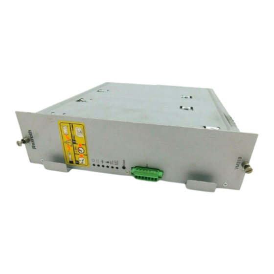
- Página 7 3 609 929 A96/06.04 | VM310 Bosch Rexroth AG 7 /52 4 Montagehinweis Gefährliche Körperströme durch Montagehinweis unzureichende Schutzleiterverbin- Das Versorgungsmodul VM310 ist in den äu- dungen! ßerst linken Einschubschacht im Baugrup- Schutzleiterverbindungen dürfen penträger BT300 bzw. in die Systembox nicht durch mechanische, chemi- SB30x einzuschieben.
- Página 8 8 /52 Bosch Rexroth AG VM310 | 3 609 929 A96/06.04 5 Inbetriebnahme Inbetriebnahme Signal Beschreibung/ Spannung/ Funktion Strom Vor der Inbetriebnahme muss der ordnungs- 24 V Versorgungs- gemäße Sitz aller Steckverbindungen sicher- spannung gestellt werden. extern 24 V / 6 A...
- Página 9 3 609 929 A96/06.04 | VM310 Bosch Rexroth AG 9 /52 5 Inbetriebnahme Anzeigen und Bedienelemente Temperatur- und Spannungsfehler können nur durch Aus- und Einschalten des gesam- ten Systems oder durch Drücken des Reset- Tasters auf der Frontplatte zurückgesetzt werden.
- Página 10 Anhaftungen wie Öle, Fette oder sonstige Verunreinigungen enthal- Schutzrecht ten sind. Weiterhin dürfen bei der Rücksendung keine © Alle Rechte bei Bosch Rexroth AG, auch unangemessenen Fremdstoffe oder Fremd- für den Fall von Schutzrechtsanmeldungen. komponenten enthalten sein. Jede Verfügungsbefugnis, wie Kopier- und Die Produkte sind frei Haus an folgende Weitergaberecht, bei uns.
- Página 11 3 609 929 A96/06.04 | VM310 Bosch Rexroth AG 11 /52 11 Vertrieb...
- Página 12 12 /52 Bosch Rexroth AG VM310 | 3 609 929 A96/06.04 1 Technical Data Technical Data Designation VM310 Order number 0 608 750 109 Input Supply voltage 1 x 230 V or 3 x 230 V (± 10 %), 50 - 60 Hz...
- Página 13 3 609 929 A96/06.04 | VM310 Bosch Rexroth AG 13/52 2 Intended Use Intended Use Safety Notes The supply module VM310 is intended to be The data specified above only serve to installed in the BT300 card rack or the describe the product.
- Página 14 14/52 Bosch Rexroth AG VM310 | 3 609 929 A96/06.04 3 Safety Notes Repairs and replacement of parts carried out Danger to life due to insufficient by the user are his own responsibility. After emergency off devices! repairing or replacing parts, all prescribed...
- Página 15 3 609 929 A96/06.04 | VM310 Bosch Rexroth AG 15/52 4 Assembly Instructions Danger of shock due to insufficient Assembly Instructions protective conductor connections! The supply module VM310 must be inserted Protective conductor connections into the 1st left slide-in slot in the BT300 card must not be impaired by mechani- rack or the SB30x system box.
- Página 16 16/52 Bosch Rexroth AG VM310 | 3 609 929 A96/06.04 5 Initial Operation Initial Operation Signal Description/ Voltage/ Function Current Before first operation, the proper seat of all 24 V Supply voltage jumpers must be ensured. external 24 V / 6 A...
- Página 17 3 609 929 A96/06.04 | VM310 Bosch Rexroth AG 17/52 5 Initial Operation Control elements and indicators Temperature and voltage errors can only be reset by switching the entire system off and on, or by pressing the reset button on the front plate.
- Página 18 Additionally, returned products must not con- fications and other information set forth in it, tain any inappropriate foreign matter or un- are the exclusive property of Bosch Rexroth known components. AG. It may not be reproduced or given to Please return products to the following ad- third parties without its consent.
- Página 19 3 609 929 A96/06.04 | VM310 Bosch Rexroth AG 19/52 11 Sales...
- Página 20 20/52 Bosch Rexroth AG VM310 | 3 609 929 A96/06.04 1 Données techniques Données techniques Désignation VM310 N° de référence 0 608 750 109 Entrée Tension d'entrée 1 x 230 V ou 3 x 230 V (± 10 %), 50 - 60 Hz Courant d'entrée...
- Página 21 3 609 929 A96/06.04 | VM310 Bosch Rexroth AG 21/52 2 Utilisation conforme Utilisation conforme Instructions de sécurité Le module d'alimentation VM310 est conçu Les indications données servent exclusive- pour être enfiché dans le rack BT300 ou le ment à la description du produit. Il ne peut boîtier de système SB30x.
- Página 22 22/52 Bosch Rexroth AG VM310 | 3 609 929 A96/06.04 3 Instructions de sécurité – personnel de mise en service, sont Ceci peut entraîner de graves autorisées à mettre en service, à relier à la dommages corporels, matériels ou terre et à marquer les circuits électriques nuire à...
- Página 23 3 609 929 A96/06.04 | VM310 Bosch Rexroth AG 23/52 4 Instructions de montage TENSIONS ÉLECTRIQUES Instructions de monta- DANGEREUSES Sauf indications contraires, les tra- vaux de maintenance doivent être Enficher le module d'alimentation VM310 effectués en principe lorsque l’ins- dans le logement se trouvant à...
- Página 24 24/52 Bosch Rexroth AG VM310 | 3 609 929 A96/06.04 5 Mise en service Mise en service Bro- Signal Description/ Tension/ Fonction Courant Avant la mise en service, s’assurer de la posi- 24 V Alimentation en tion conforme de tous les raccords enficha-...
- Página 25 3 609 929 A96/06.04 | VM310 Bosch Rexroth AG 25/52 5 Mise en service Eléments de commande et d’affichage Pour remédier aux erreurs de température et de tension, vous pouvez uniquement débran- cher puis brancher à nouveau tout le système ou enfoncer le bouton Reset situé...
- Página 26 éliminés, à condition toutefois qu’ils ne por- Droit de protection tent aucune trace gênante telle que des tra- © Tous droits réservés par Bosch Rexroth ces d’huile, de graisse ou autres impuretés. AG, y compris en cas de dépôt d’une deman- En outre, ils ne doivent contenir aucune ma- de de droit de propriété...
- Página 27 3 609 929 A96/06.04 | VM310 Bosch Rexroth AG 27/52 11 Distribution...
- Página 28 28/52 Bosch Rexroth AG VM310 | 3 609 929 A96/06.04 1 Dati tecnici Dati tecnici Denominazione VM310 Codice d’ordinazione 0 608 750 109 Ingresso Tensione d’ingresso 1 x 230 V o 3 x 230 V (± 10 %), 50 - 60 Hz Corrente d’ingresso...
- Página 29 3 609 929 A96/06.04 | VM310 Bosch Rexroth AG 29/52 2 Uso conforme Uso conforme Avvertenze di sicurezza Il modulo di alimentazione VM310 è stato Le informazioni fornite servono solo alla concepito per essere inserito nel rack BT300 descrizione del prodotto. Da esse non si può...
- Página 30 30/52 Bosch Rexroth AG VM310 | 3 609 929 A96/06.04 3 Avvertenze di sicurezza – che in quanto addette alla messa in Pericolo di morte dovuto a disposi- funzione sono autorizzate a far tivi di arresto di sicurezza insuffi- funzionare, mettere a terra e...
- Página 31 3 609 929 A96/06.04 | VM310 Bosch Rexroth AG 31/52 4 Istruzioni di montaggio Correnti pericolose nel corpo do- Istruzioni di montaggio vute a collegamenti dei conduttori Il modulo di alimentazione VM310 deve esse- di protezione insufficienti! re inserito nell’ultimo vano d’inserimento a si-...
- Página 32 32/52 Bosch Rexroth AG VM310 | 3 609 929 A96/06.04 5 Messa in funzione Messa in funzione Segnale Descrizione/ Tensione/ Funzione Corrente Prima della messa in funzione assicurarsi che 24 V tensione di tutti i connettori siano perfettamente innestati. alimentazione...
- Página 33 3 609 929 A96/06.04 | VM310 Bosch Rexroth AG 33/52 5 Messa in funzione Elementi di comando ed indi- catori Gli errori relativi alla temperatura e alla tensi- one possono essere annullati solo spegnen- do e riaccendendo l’intero sistema oppure...
- Página 34 Diritti di protezione Inoltre nella spedizione di ritorno non devono essere contenuti additivi o componenti ester- © Tutti i diritti sono riservati alla Bosch ni inopportuni. Rexroth AG, anche nel caso di deposito di di- I prodotti devono essere inviati franco domi- ritti di protezione.
- Página 35 3 609 929 A96/06.04 | VM310 Bosch Rexroth AG 35/52 11 Rete distributiva...
- Página 36 36/52 Bosch Rexroth AG VM310 | 3 609 929 A96/06.04 1 Datos técnicos Datos técnicos Denominación VM310 N° de referencia 0 608 750 109 Entrada Tensión de entrada 1 x 230 V ó 3 x 230 V (± 10 %), 50 - 60 Hz Corriente de entrada depende de la tensión y del tipo de conexión,...
- Página 37 3 609 929 A96/06.04 | VM310 Bosch Rexroth AG 37/52 2 Concepción de uso Concepción de uso Instrucciones de seguridad El módulo de alimentación VM310 ha sido concebido para el montaje en el chasis por- Los datos indicados sirven sólo para descri- tamódulos BT300 ó...
- Página 38 38/52 Bosch Rexroth AG VM310 | 3 609 929 A96/06.04 3 Instrucciones de seguridad – como personal de puesta en servicio, Peligro de vida por insuficientes están habilitados para la puesta en servi- dispositivos de paro de emergen- cio, conexión a tierra y señalización del cir-...
- Página 39 3 609 929 A96/06.04 | VM310 Bosch Rexroth AG 39/52 4 Instrucciones de montaje ¡Peligrosas corrientes estructura- Instrucciones de mon- les por insuficientes conexiones taje de conductores de protección! Las conexiones de conductores Introducir el módulo de alimentación VM310 de protección no deben estar per- en el primer compartimento del lado izquier- judicadas por influencias mecáni-...
- Página 40 40/52 Bosch Rexroth AG VM310 | 3 609 929 A96/06.04 5 Puesta en servicio Puesta en servicio Pin Señal Descripción/ Tensión/ Función Corriente Asegurarse de la instalación correcta de to- 24 V tensión de alimenta- dos los empalmes de conexión antes de la ción externa...
- Página 41 3 609 929 A96/06.04 | VM310 Bosch Rexroth AG 41/52 5 Puesta en servicio Elementos de manejo e indicadores Los errores de temperatura y tensión pueden ser remediados tan sólo desconectando y después conectando el sistema completo o pulsando el botón de inicialización situado en la placa frontal.
- Página 42 Derecho de propiedad que no exista ningún tipo de acumulación molesta de aceite, grasas u otras impurezas. © Todos los derechos de Bosch Rexroth AG, también para el caso de solicitudes de Además, en los productos devueltos tampo- derechos protegidos. Nos reservamos todas...
- Página 43 3 609 929 A96/06.04 | VM310 Bosch Rexroth AG 43/52 11 Distribución...
- Página 44 44/52 Bosch Rexroth AG VM310 | 3 609 929 A96/06.04 1 Dados técnicos Dados técnicos Especificação VM310 Número para encomenda 0 608 750 109 Entrada Tensão de entrada 1 x 230 V ou 3 x 230 V (± 10 %), 50 - 60 Hz Corrente de entrada dependendo da tensão e do tipo de conexão,...
- Página 45 3 609 929 A96/06.04 | VM310 Bosch Rexroth AG 45/52 2 Uso correto Uso correto Instruções de segurança O módulo de alimentação VM310 é destina- do à instalação no porta conjuntos BT300 ou Os dados indicados destinam-se unicamente na caixa de sistema SB30x. O módulo de ali- a descrever o produto.
- Página 46 46/52 Bosch Rexroth AG VM310 | 3 609 929 A96/06.04 3 Instruções de segurança – tendo competência como pessoal para Alterações ou reconfigurações po- colocação em operação de circuitos dem influenciar a segurança dos elétricos e sistemas de aparelhos, fazer produtos descritos! aterramentos e identificações de acordo...
- Página 47 3 609 929 A96/06.04 | VM310 Bosch Rexroth AG 47/52 4 Instrução de montagem TENSÕES ELÉTRICAS Instrução de monta- PERIGOSAS Se não for indicado de outra for- ma, serviços de manutenção só O módulo de alimentação VM310 deve ser devem ser executados com a má-...
- Página 48 48/52 Bosch Rexroth AG VM310 | 3 609 929 A96/06.04 5 Início de operação Início de operação Pino Sinal Descrição/ Tensão/ Função Corrente Antes do inicio de operação deverá ser asse- 24 V Tensão de alimen- gurado perfeito assentamento das conexões tação externa...
- Página 49 3 609 929 A96/06.04 | VM310 Bosch Rexroth AG 49/52 5 Início de operação Elementos de operação e indicações Falhas de temperatura ou tensão, somente podem ser revogados pelo desligar e ligar do sistema completo ou apertando a tecla RE- SET na placa frontal.
- Página 50 Propriedade industrial como óleos, graxas ou outros poluentes. Além disso, o envio de volta não deve conter © Bosch Rexroth AG, todos os direitos re- nenhuma substância ou componentes estra- servados, também em caso de pedidos de nhos inapropriados.
- Página 51 3 609 929 A96/06.04 | VM310 Bosch Rexroth AG 51/52 11 Vendas...
- Página 52 Bosch Rexroth AG Electric Drives and Controls Schraub- und Einpress-Systeme Postfach 1161 D - 71534 Murrhardt Fax +49 (0) 71 92 22-1 81 e-mail: schraubtechnik@boschrexroth.de http://www.boschrexroth.com/schraubtechnik 0 6 0 4 3 6 0 9 9 2 9 A 9 6 Ihr Vertragshändler...