Publicidad
Enlaces rápidos
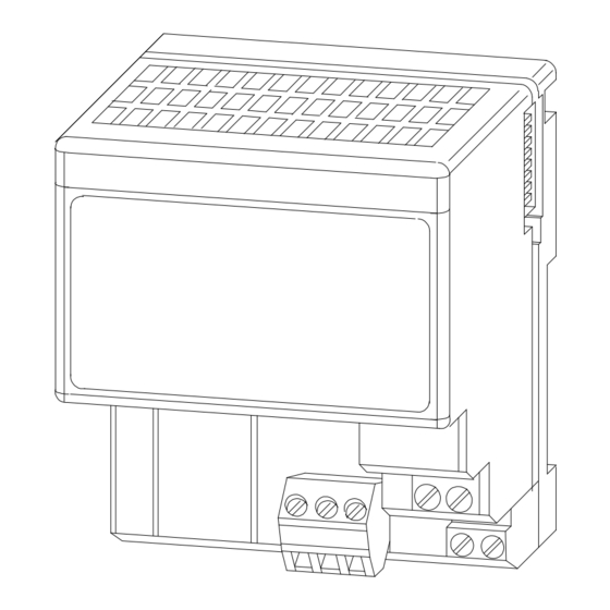
To install the mounting plate on a wall or panel, proceed as follows:
1. Lay out the required points on the wall/panel as shown in the drilling
dimension drawing.
2. Drill the necessary holes for 6–32 mounting screws.
3. Mount the mounting plate (1) for the adapter module using two 6–32 screws
(18 included).
o
4. Hold the adapter (2) at a 30
in the indention on the rear of the adapter module.
5. Press the module down flush with the panel until the locking lever locks.
6. Position the termination base unit up against the adapter and push the female
bus connector into the adapter.
7. Secure to the wall with two 6–32 screws.
8. Repeat for each remaining terminal base unit.
Note: The adapter is capable of addressing eight modules. Do not exceed a
maximum of eight terminal base units in your system.
Per installare la piastra di montaggio su parete o pannello, procedete come segue:
1. Segnate i punti richiesti sulla parete/pannello come indicato nel disegno delle
dimensioni dei fori.
2. Perforate i fori necessari per viti di montaggio 6–32.
3. Montate la piastra di montaggio (1) per il modulo adattatore usando viti 6–32.
4. Tenete l'adattatore (2) ad un angolo di 30
della piastra di montaggio nella rientranza sul retro del modulo adattatore.
5. Premete il modulo in modo che sia allineato al pannello finché non si blocca
la leva di bloccaggio.
6. Posizionate la morsettiera base contro l'adattatore e spingete il connettore bus
femmina nell'adattatore.
7. Fissate alla parete con due viti 6–32.
8. Fate la stessa cosa per ogni morsettiera base.
Nota: L'adattatore è in grado di indirizzare otto moduli. Nel vostro sistema non
superate il massimo di otto morsettiere base.
Pour installer la plaque de montage sur un mur ou un panneau, procédez selon les
étapes ci-dessous :
1. Etablissez les points nécessaires sur le mur ou le panneau, selon les
instructions du schéma des dimensions de montage.
2. Percez les trous pour les vis de montage 6x32.
3. Installez la plaque de montage (1) du module adaptateur à l'aide de deux vis
6x32.
4. Maintenez l'adaptateur (2) en position à 30 et engagez le haut de la plaque de
montage dans l'espace prévu à l'arrière du module adaptateur.
angle and engage the top of the mounting plate
o
ed impegnate la parte superiore
5. Faites pression vers le bas sur le module pour le mettre à niveau avec le
panneau et bloquer les pattes de verrouillage.
6. Positionnez le socle à bornier contre l'adaptateur et engagez le connecteur bus
femelle dans l'adaptateur.
7. Fixez au mur à l'aide de deux vis 6x32.
8. Réitérez la procédure pour chaque socle à bornier.
Remarque : L'adaptateur est capable d'adresser huit modules. Votre système ne
doit pas dépasser huit socles à bornier.
Para instalar la placa de montaje en una pared o panel, proceda de la siguiente
forma:
1. Haga el esquema de los puntos requeridos en la pared/panel, tal como se
muestra en el dibujo de dimensiones para taladro.
2. Taladre los agujeros necesarios para los tornillos 6–32.
3. Instale la placa de montaje (1) para el módulo adaptador, usando dos tornillos
6–32.
4. Sujete el adaptador (2) a un ángulo de 30
placa de montaje en la muesca que se encuentra en la parte posterior del
módulo adaptador.
5. Presione el módulo hacia abajo, hasta que esté al mismo nivel con el panel, y
hasta que enganche la palanca de fijación.
6. Coloque la unidad base contra el adaptador y empuje el conector de bus
hembra en el adaptador.
7. Asegúrelo a la pared/panel con dos tornillos 6–32.
8. Repita el procedimiento para cada unidad base.
Nota: El adaptador puede direccionar ocho módulos. No instalar más de ocho
unidades base en su sistema.
Nota: El adaptador puede direccionar ocho módulos. No instalar más de ocho
unidades base en su sistema.
o
y enganche la parte superior de la
1
Publicidad

Manuales relacionados para Rockwell Automation Allen-Bradley 1794-NM1


Resumen de contenidos para Rockwell Automation Allen-Bradley 1794-NM1
- Página 1 To install the mounting plate on a wall or panel, proceed as follows: 1. Lay out the required points on the wall/panel as shown in the drilling dimension drawing. 2. Drill the necessary holes for 6–32 mounting screws. 3. Mount the mounting plate (1) for the adapter module using two 6–32 screws (18 included).
- Página 2 Die Montageplatte wird wie folgt an der Wand bzw. an einem Bedienpult installiert: 1. Die erforderlichen Punkte entsprechend den abgebildeten Bohrabmessungen auslegen. 2. Die benötigten Löcher für 6–32-Schrauben bohren. 3. Die Montageplatte (1) des Adaptermoduls mit zwei 6–32-Schrauben befestigen. 4. Den Adapter (2) im Winkel von 30 halten und den oberen Rand der Montageplatte in die an der Rückseite des Adaptermoduls befindliche Vertiefung einsetzen.