Publicidad
Idiomas disponibles
Idiomas disponibles
Enlaces rápidos
Safe Operation Practices • Set-Up • Operation • Maintenance • Service • Troubleshooting • Warranty
O
'
M
peratOr
s
anual
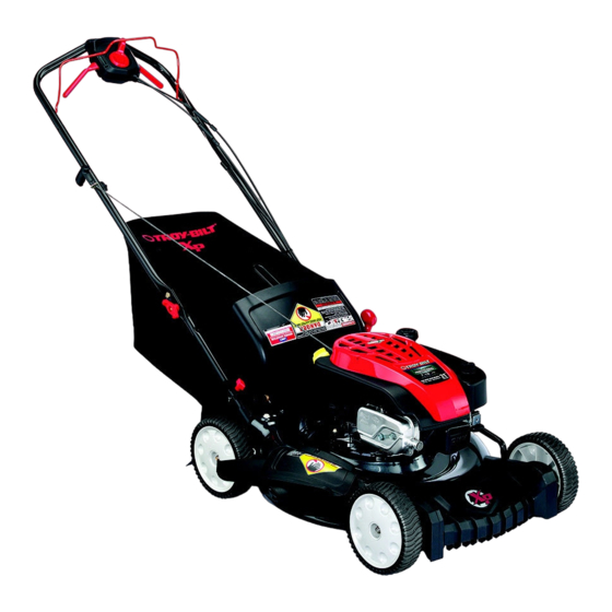
Self Propelled Mower — Models TB330 XP/ TB350 XP
WARNING
READ AND FOLLOW ALL SAFETY RULES AND INSTRUCTIONS IN THIS MANUAL
BEFORE ATTEMPTING TO OPERATE THIS MACHINE.
FAILURE TO COMPLY WITH THESE INSTRUCTIONS MAY RESULT IN PERSONAL INJURY.
TROY-BILT LLC, P.O. BOX 361131 CLEVELAND, OHIO 44136-0019
Printed In USA
Form No. 769-06390
(December 20, 2010)
Publicidad

Manuales relacionados para Troy-Bilt TB330 XP


Resumen de contenidos para Troy-Bilt TB330 XP
- Página 1 Safe Operation Practices • Set-Up • Operation • Maintenance • Service • Troubleshooting • Warranty ’ peratOr anual Self Propelled Mower — Models TB330 XP/ TB350 XP WARNING READ AND FOLLOW ALL SAFETY RULES AND INSTRUCTIONS IN THIS MANUAL BEFORE ATTEMPTING TO OPERATE THIS MACHINE.
- Página 2 Choose from the options below: ◊ Visit us on the web at www.troybilt.com ◊ Call a Customer Support Representative at (800) 828-5500 or (330) 558-7220 ◊ Write us at Troy-Bilt LLC • P.O. Box 361131 • Cleveland, OH • 44136-0019...
- Página 3 Important Safe Operation Practices WARNING: This symbol points out important safety instructions which, if not followed, could endanger the personal safety and/or property of yourself and others. Read and follow all instructions in this manual before attempting to operate this machine. Failure to comply with these instructions may result in personal injury.
- Página 4 A missing or damaged discharge cover can cause blade When starting engine, pull cord slowly until resistance contact or thrown object injuries. is felt, then pull rapidly. Rapid retraction of starter cord (kickback) will pull hand and arm toward engine faster than Many injuries occur as a result of the mower being pulled you can let go.
- Página 5 Service Check the blade and engine mounting bolts at frequent intervals for proper tightness. Also, visually inspect blade Safe Handling Of Gasoline: for damage (e.g., bent, cracked, worn) Replace blade with the original equipment manufacture’s (O.E.M.) blade only, To avoid personal injury or property damage use extreme listed in this manual.
- Página 6 Notice Regarding Emissions Spark Arrestor Engines which are certified to comply with California and federal WARNING: This machine is equipped with an EPA emission regulations for SORE (Small Off Road Equipment) internal combustion engine and should not be used are certified to operate on regular unleaded gasoline, and on or near any unimproved forest-covered, brush may include the following emission control systems: Engine covered or grass-covered land unless the engine’s...
- Página 7 Safety Symbols This page depicts and describes safety symbols that may appear on this product. Read, understand, and follow all instructions on the machine before attempting to assemble and operate. Symbol Description READ THE OPERATOR’S MANUAL(S) Read, understand, and follow all instructions in the manual(s) before attempting to assemble and operate DANGER —...
- Página 8 2 — i ectiOn MpOrtant peratiOn ractices...
- Página 9 Assembly & Set-Up Contents of Carton • One Lawn Mower • One Grass Catcher • One Bottle of Oil • One Lawn Mower Operator’s Manual • One Engine Operator’s Manual • One Side Discharge Chute NOTE: Please be aware that this Operator’s Manual covers both While stabilizing mower so it doesn’t move, pivot the low and high wheel models of this mower.
- Página 10 Remove the T-bolts from the handle brackets as shown in Fig. 3-3. Figure 3-5 The rope guide is attached to the right side of the upper handle. Loosen the wing knob which secures the rope Figure 3-3 guide. See Fig. 3-6. Hold blade control against upper handle.
- Página 11 Slip plastic channel of grass bag over hooks on the On the side of the mower, lift the side mulching plug. See frame. See Fig. 3-7. Figure 3-9. Side Mulching Plug Figure 3-9 Figure 3-7 Follow steps below to attach grass catcher: Slide two hooks of side discharge chute under hinge pin on mulching plug assembly.
- Página 12 Drive Control The adjustment wheel is located in the drive control handle Higher housing and is used to tighten or loosen the drive belt. You will need to adjust the drive control if the mower does not propel itself with the drive control engaged or if the mower’s wheels hesitate with the drive control engaged.
- Página 13 Controls and Features Drive Control Blade Control Speed Control Drive Control Recoil Starter Cutting Height Adjustment Lever Deck Wash Side Discharge Chute Figure 4-1 Blade Control Cutting Height Adjustment Lever The blade control is attached to the upper handle of the mower. The cutting height adjustment lever is located above the left Depress and squeeze it against the upper handle to operate the rear wheel.
- Página 14 Operation Starting Engine WARNING: Be sure no one other than the operator is standing near the lawn mower while starting engine or operating mower. Never run engine indoors or in enclosed, poorly ventilated areas. Engine exhaust contains carbon monoxide, an odorless and deadly gas.
- Página 15 Using as Mulcher Using Grass Catcher For mulching grass, remove the grass catcher and allow the rear You can use the grass catcher to collect clippings while you are discharge door to close the rear opening of mower. For effective operating the mower.
- Página 16 Maintenance & Adjustments Maintenance The transmission is pre-lubricated and sealed at the factory and does not require lubrication. General Recommendations Follow the accompanying engine manual for lubrication schedule and instruction for engine lubrication. • Always observe safety rules when performing any maintenance.
- Página 17 Deck Wash (If Equipped) Engine Care Your mower’s deck may be equipped with a water port on its A list of key engine maintenance jobs required for good surface as part of its deck wash system. performance by the mower is given below. Follow the accompanying engine manual for a detailed list and instructions.
- Página 18 Service Blade Care Place blade bell support on the blade. Align notches on the blade bell support with small holes in blade. WARNING: When removing the cutting blade for Replace hex bolt and tighten hex bolt to torque: 450 in. lbs. sharpening or replacement, protect your hands with min., 600 in.
- Página 19 Troubleshooting Problem Cause Remedy Engine Fails to start Blade control disengaged. Engage blade control. Spark plug boot disconnected. Connect wire to spark boot. Fuel tank empty or stale fuel. Fill tank with clean, fresh gasoline. Engine not primed (if equipped with primer). Prime engine as instructed in the Operation section.
- Página 20 Problem Cause Remedy Uneven cut Dull blade. Sharpen or replace blade. Mower will not self propel Belt not installed properly. Check belt for proper pulley installation and movement. Debris clogging drive operation. Stop engine, disconnect spark plug boot, and clean out debris. Damaged or worn belt.
- Página 21 Replacement Parts Component Part Number and Description 759-3336 Spark Plug BS-795066 Air Filter Cartridge BS-796254 Pre-Cleaner BS-692046 Fuel Tank Cap (Model 11P902-2693-B1) BS-796577 Fuel Tank Cap (Model 111P02-2693-F1) 734-04564 Wheel (Front) 634-04681 Wheel (Rear - Low) 634-04666 Wheel (Rear - High) 731-07131 Discharge Chute 942-0741A...
- Página 22 MANUFACTURER’S LIMITED WARRANTY FOR The limited warranty set forth below is given by Troy-Bilt LLC with c. Routine maintenance items such as lubricants, filters, blade respect to new merchandise purchased and used in the United States sharpening, tune-ups, brake adjustments, clutch adjustments,...
- Página 23 LEA Y SIGA TODAS LAS INSTRUCCIONES DE ESTE MANUAL ANTES DE PONER EN FUNCIONAMIENTO ESTA MÁQUINA. SI NO RESPETA ESTAS INSTRUCCIONES PUEDE PROVOCAR LESIONES PERSONALES. TROY-BILT LLC, P.O. BOX 361131 CLEVELAND, OHIO 44136-0019 Impreso en Estados Unidos de América Formulario No. 769-06390...
- Página 24 Elija entre las opciones que se presentan a continuación: ◊ Visite nuestro sitio web en www.troybilt.com ◊ Llame a un representante de Asistencia al Cliente al (800) 828-5500 ó (330) 558-7220 ◊ Escríbanos a Troy-Bilt LLC • P.O. Box 361131 • Cleveland, OH • 44136-0019...
- Página 25 Medidas importantes de seguridad ADVERTENCIA: La presencia de este símbolo indica que se trata de instrucciones importantes de seguridad que se deben respetar para evitar poner en peligro su seguridad personal y/o material y la de otras personas. Lea y siga todas las instrucciones de este manual antes de poner en funcionamiento esta máquina.
- Página 26 No ponga las manos o los pies cerca de las piezas rotatorias Nunca opere la cortadora sin las guardas apropiadas, o en la tolva de la cortadora. El contacto con las cuchillas cubierta de descarga, guarda para recorte, manija de puede producir la amputación de manos y pies.
- Página 27 Niños Nunca saque la tapa del gas ni agregue combustible mientras el motor está caliente o en marcha. Deje que el Pueden ocurrir accidentes trágicos si el operador no está atento motor se enfríe por lo menos dos minutos antes de volver a a la presencia de niños.
- Página 28 No modifique el motor Nunca trate de ajustar una rueda o la altura de corte mientras el motor está en marcha. Para evitar lesiones graves o la muerte, no modifique el motor Los componentes de la tolva para recorte, cubierta bajo ninguna circunstancia.
- Página 29 Símbolos De Seguridad Esta página representa y describe la seguridad los símbolos que pueden parecer en este producto. Lea, comprenda, y siga todas instrucciones de la máquina antes de intentar ensamblar y operar. Símbolo Descripción LEA EL MANUAL(S) DEL OPERADOR Lea, comprenda, y siga todas instrucciones en el manual (manuales) antes de operar el producto.
- Página 30 2 — M ección edidas iMpOrtantes de seguridad...
- Página 31 Montaje y Configuración Contenido de la caja • Una Podadora • Uno Colector de Césped • Uno Botella del Aceite • Uno Manual de Operador • Uno Manual de Operador de Motor • Uno Canal de Descarga Lateral NOTA: Tenga en cuenta que este manual del operador abarca tanto los modelos de rueda alta y baja de este cortacésped.
- Página 32 Siga los siguientes pasos para completar conjunto del La guía de la cuerda está unida al costado derecho de la mango: manija superior. Afloje la tuerca de mariposa que sujeta la guía de la cuerda, fig. 3-6. Tire hacia arriba aproximadamente 8 pulgadas en el asa hasta agujeros en la manija (que se muestra en la figura.
- Página 33 En el costado de la podadora, levante el adaptador para abono. Vea fig. 3-9. Clavija para abono lateral Figura 3-7 Para acoplar el colector de césped. Figura 3-9 Levante la puerta de descarga posterior. Deslice los dos ganchos del canal de descarga lateral Lugar de colección de césped en las ranuras en el debajo del pasador de bisagra sobre el montaje del mango entre corchetes como se muestra en la fig.
- Página 34 Control de transmisión La rueda de ajuste está ubicada en el alojamiento de la manija de control de transmisión y se utiliza para ajustar o aflojar la Superior correa de transmisión. Deberá ajustar el control de transmisión si la podadora no se autopropulsa con el control de transmisión enganchado o si las ruedas de la podadora vacilan con el control de transmisión enganchado.
- Página 35 Controles Y Características Control de la transmisión Control de Control de la Velocidad cuchilla Control de la transmisión Palanca de Arrancador ajuste de altura de retroceso de corte Lavado de la Plataforma Canal de Descarga Lateral Figura 4-1 Control de Cuchilla motor corre.
- Página 36 Funcionamiento Encendido del Motor ADVERTENCIA: Asegúrese que ninguna persona aparte del operador permanezca cerca de la podadora mientras arranca el motor u opera la misma. Nunca encienda un motor en espacios cerrados o en una zona con poca ventilación. El escape del motor contiene monóxido de carbono, un gas inodoro y letal.
- Página 37 Uso del Colector de Césped NOTA: La máquina está equipada con un avanzado sistema de tracción interior de la facilidad de uso y cambios suaves. Puede utilizar el colector de césped para recoger dichos recortes Al girar o tirar de la unidad hacia atrás, usted puede notar mientras opera la podadora.
- Página 38 Mantenimiento Y Ajustes Mantenimiento La transmisión estado prelubricada y sellada en la fábrica y no requiere lubricación. Recomendaciones Generales Siga el manual adjunto del motor para conocer las instrucciones y el programa de lubricación del mismo. • Respete siempre las reglas de seguridad cuando realice tareas de mantenimiento.
- Página 39 Lavado de la Plataforma (De ser equipado) Cuidados para el motor La plataforma de su podadora está equipada con un puerto de A continuación se presenta una lista de tareas de mantenimiento agua sobre su superficie como parte del sistema de lavado de la necesarias para el buen funcionamiento de la cortadora de plataforma.
- Página 40 Servicio Cuidado de la Cuchilla Para comprobar el equilibrio, retire la cuchilla y balancee sobre un destornillador de eje redondo. ADVERTENCIA: Cuando saque la cuchilla de corte Saque metal del lado pesado hasta que quede bien para afilarla o reemplazarla, protéjase las manos equilibrada.
- Página 41 Consulte el manual del motor para conocer las el cinturón del cortacésped. Ver a un Distribuidor de Servicio de instrucciones para el almacenamiento correcto del mismo. Troy-Bilt autorizado para hacer sustituir su cinturón. • Almacene la unidad en una zona limpia y seca. No la...
- Página 42 Solución de problemas Problema Causa Remedio El motor no arranca El control de lámina se retiró. Contratar el control de lámina. Alambre de bujía desconectado. Unir el alambre a la bujía. Depósito de combustible combustible vacío Llenar el tanque de la gasolina limpia, fresca. o añejo.
- Página 43 Problema Causa Remedio Demasiada vibración Cuchilla floja o desequilibrada. Apriete la cuchilla y el adaptador. Equilibre la cuchilla. Cuchilla abollada. Consulte a un distribuidor autorizado. La podadora no abona Césped húmedo. No corte el césped cuando está mojado, el césped espere hasta que sea más tarde para hacerlo.
- Página 44 Las disposiciones de esta garantía cubren el recurso de reparación zapatas antideslizantes, ruedas de fricción, placas de raspado, gomas única y exclusiva que surge de la venta. Troy-Bilt no se hará helicoidales y neumáticos. responsable de ninguna pérdida o daño incidental o resultante, incluyendo sin limitación, los gastos incurridos para los servicios...