
Manuales relacionados para Optimus A8000X Serie


Resumen de contenidos para Optimus A8000X Serie
- Página 1 SERIE A8000X A8000X SERIES Manual de instalación y funcionamiento v1.4 Installation and operating instructions v1.4...
-
Página 2: Instrucciones De Seguridad
Serie A8000X INSTRUCCIONES DE SEGURIDAD: IMPORTANTE: Los códigos de color de los cables de red son los siguientes: Verde y amarillo Tierra Azul Neutro Marrón Positivo Si los colores de los cables de red de este aparato no se corresponden con las marcas de sus terminales de conexión, debe procederse como sigue: Conectar el cable de color verde y amarillo al terminal marcado con la letra E o con el símbolo de tierra. -
Página 3: Tabla De Contenido
Serie A8000X ÍNDICE EQUIPOS DEL SISTEMA .................... 4 A-8240X ......................4 CD-7 ........................4 AWP-06 ......................4 APS-06 ....................... 4 APS-EX ......................5 AEX-8000 ......................5 PANEL FRONTAL A-8240X.................. - Página 4 Serie A8000X FUNCIONAMIENTO CD-7 ..................26 13.1 Modo CD / USB / SD ..................26 13.2 Modo Radio ...................... 27 13.3 Memoria ......................28 ESPECIFICACIONES TÉCNICAS A-8240X .............. 29 ESPECIFICACIONES TÉCNICAS AWP-06............... 30 ...
-
Página 5: Equipos Del Sistema
Serie A8000X 1. EQUIPOS DEL SISTEMA A-8240X • Amplificador mezclador de seis zonas con seis entradas de micrófono. • Cada entrada dispone de un potenciómetro para ajustar el nivel de la señal. • Cada entrada dispone de un potenciómetro de ajuste para altas y bajas frecuencias. •... -
Página 6: Aps-Ex
Serie A8000X APS-EX • Expansión de 12 teclas para APS-06. • LED indicador de estado para cada zona. • Pueden instalarse 4 unidades por cada APS-06. 1.6 AEX-8000 • El AEX-8000 se utiliza como equipo de expansión de zonas. • Las zonas expandidas pueden ser controladas desde el micrófono o manualmente pulsando el interruptor del frontal. -
Página 7: Panel Frontal A-8240X
Serie A8000X 2. PANEL FRONTAL A-8240X (1) Controles de volumen de MIC 1~4. (8) Controlador de volumen general. (2) Controles de tono agudos/graves para (9) Indicador LED de encendido. MIC1~4. (10) Indicador LED de fallo. (3) Controles de volumen de MIC5/LINE1 y (11) Interruptor de llamada general. -
Página 8: Panel Posterior A-8240X
Serie A8000X 3. PANEL POSTERIOR A-8240X (16) Interruptor de encendido. (37) Interruptor Phantom ON/OFF MIC1/2. (17) Entrada de alimentación de corriente (38) Interruptor de PTT (Push to Talk). alterna. (39) Conector XLR de entrada MIC1. (18) Fusible de protección. (40) Conector RJ45 de entrada MIC1. (19) Terminal de entrada 24 Vcc. -
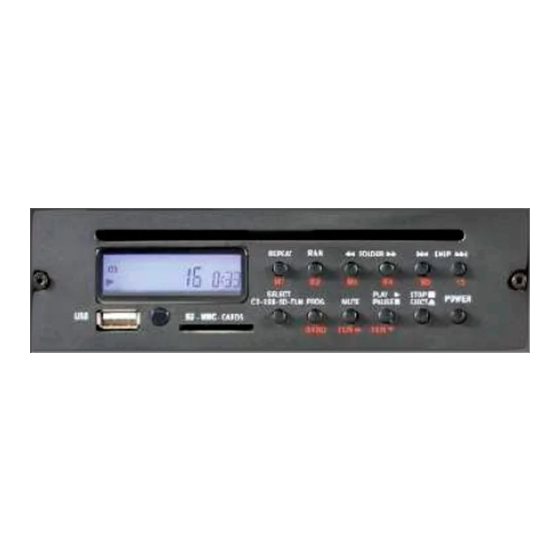
Página 9: Panel Frontal Cd-7
Serie A8000X 4. PANEL FRONTAL CD-7 (1) Conector de entrada USB. (2) Receptor IR. (3) Ranura para tarjeta SD. (4) Selector de fuente CD / USB / SD / TUN. (5) Selector de cambio de programa/banda de radio. (6) Botón Mute / incremento sintonía de radio. (7) Botón de reproducción / pausa o decrementa la sintonía de radio. -
Página 10: Panel Frontal Awp-06
Serie A8000X 5. PANEL FRONTAL AWP-06 (1) Interruptores y LEDs selectores (5) Controlador del nivel de mezcla. de zonas y llamada general. (6) Pulsador de encendido. (2) Selector de fuente de sonido / (7) Regulador de volumen general. AUX 1~3. (8) Conector de datos (Panel posterior). -
Página 11: Panel Frontal Aps-06
Serie A8000X 6. PANEL FRONTAL APS-06 (1) Conector para micrófono. (5) Botón de hablar con enclavamiento. (2) Botones de zona. (6) Botón de pulsar para hablar PTT. (3) Botón de llamada general. (4) Indicadores LED de Talk / Busy. 7. PANEL POSTERIOR APS-06 (7) Regulador de nivel del audio de salida. -
Página 12: Aps-Ex
Serie 8000 8. APS-EX (1) Pulsadores de zona. (2) Indicadores LED de zona. (3) Conector de entrada (4) Conector de salida. 9. PANEL FRONTAL AEX-8000 (1) Pulsadores de selección de zona. (5) Indicadores LED de fallo Amp1 / Amp2. (Sin uso) (2) Indicadores LED de zona. -
Página 13: Panel Posterior Aex-8000
Serie 8000 10. PANEL POSTERIOR AEX-8000 (7) Entrada de alimentación de corriente (15) Terminal RJ-45 de salida. alterna. (16) Terminal RJ-45 de entrada. (8) Fusible de protección. (17) Regulador de nivel auxiliar. (9) Interruptor de encendido. (18) Conector RCA de entrada auxiliar. (10) Toma de tierra. -
Página 14: Instalación Y Funcionamiento
Serie A8000X 11. INSTALACIÓN Y FUNCIONAMIENTO 11.1 Seleccionar tensión de alimentación CA Nunca utilice una tensión distinta a la de la red, hacerlo podría dañar el equipo. 11.2 Conectar cable de alimentación CA 11.3 Seleccionar modo de funcionamiento Ajuste el conmutador de selección de modo a la posición OFF (arriba) para utilizar el equipo en modo “Stand Alone”. -
Página 15: Seleccionar El Tipo De Gong
Serie A8000X 11.6 Seleccionar el tipo de Gong Existen 4 configuraciones distintas seleccionables en función de la tabla siguiente: GONG GONG OFF OFF OFF GONG 1 GONG 2 GONG 3 El gong es activado desde el conector RJ45 del conector MIC1. El Gong del APS-06 está incluido en la propia unidad y no es afectado por esta configuración. -
Página 16: Conexión Entradas Bgm
Serie A8000X 11.8 Conexión entradas BGM El equipo dispone de dos tipos de entrada para fuentes musicales, XLR/JACK para AUX1 y RCA para AUX2 y AUX3. Ambos conectores no son balanceados. También puede disponer, opcionalmente, de una fuente musical integrada (CD-7) con CD-MP3 USB/SD y radio. -
Página 17: Moh Música En Espera
Serie A8000X 11.11 MOH música en espera El equipo dispone de dos tipos de conectores para la música en espera, uno a nivel de auxiliar (0 dB) y otro de baja impedancia 8 Ω (1 W) para conectar directamente un altavoz. El volumen es controlado mediante el potenciómetro MOH Level. - Página 18 Serie A8000X Sensibilidad del micrófono: Pulse las teclas TALK y Z5 simultáneamente durante 3 segundos. Los LEDs TALK y Z5 se encenderán. Pulse la tecla Z5 y el estado de los LEDs cambiará secuencialmente incrementándose la ganancia en cada salto. (LED ON = 1, LED OFF = 0). Pulse la tecla TALK para salir de la configuración.
-
Página 19: Panel Remoto Awp-06
Serie A8000X Filtro de palabra: Pulse las teclas TALK y Z2 simultáneamente durante 3 segundos. Los LEDs TALK y Z3 se encenderán. Pulse la tecla Z3 y el estado de los LEDs cambiará secuencialmente activándose y desactivándose el filtro de palabra. (LED ON = 1, LED OFF = 0). Pulse la tecla TALK para salir de la configuración. -
Página 20: Aps-Ex Conexión Y Montaje
Serie A8000X 11.15 APS-EX conexión y montaje Pueden conectarse hasta 4 unidades a un APS-06. Conecte las unidades entre ellas utilizando el cable plano incluido. Una las unidades conforme al siguiente diagrama usando los anclajes incluidos. 11.16 External Amplifier OUT Salida de audio 0 dB 600Ω... -
Página 21: Salidas De 100 V
Serie A8000X 11.18 Salidas de 100 V El A-8240X incluye 6 salidas de 100 V controladas desde el frontal del equipo, desde el pupitre APS-6 y desde el panel remoto. La impedancia total no debe ser inferior a la impedancia nominal del equipo. 11.19 0 / 8 Ω... -
Página 22: Encendido Remoto
Serie A8000X 11.20 Encendido remoto El equipo dispone de unos terminales de encendido remoto. El equipo se encenderá automáticamente cuando se conecten 24 V en dichos terminales. Para realizar esta función el interruptor de alimentación debe estar apagado. 11.21 Conexión de alimentación por baterías Puede conectarse una batería de 24 V a los terminales DC24V para alimentar el equipo en caso de fallo de la alimentación principal en CA. -
Página 23: Conexión Aex-8000
Serie A8000X 11.22 Conexión AEX-8000 Pueden conectarse 4 AEX-8000 al A-8240X, expandiendo el sistema hasta 54 zonas. La configuración de las unidades debe realizarse siguiendo la tabla siguiente: En el caso de utilizar amplificadores para aumentar la potencia debe conectarse la salida “TO AMP1/2”... -
Página 24: Ejemplos De Instalación
Serie A8000X 12. EJEMPLOS DE INSTALACIÓN 12.1 Sistema de 1 canal 6 zonas 240 W A-8240X interruptor de modo en MODE1 (arriba), interruptor 20 kHz desconectado (arriba) 12.2 Sistema de 1 canal 18 zonas 240 W A-8240X interruptor de modo en MODE1 (arriba), interruptor 20 kHz desconectado (arriba). Podría ampliarse hasta 54 zonas utilizando 4 x AEX-8000. -
Página 25: Sistema De 1 Canal 18 Zonas Hasta 360 W
Serie A8000X 12.3 Sistema de 1 canal 18 zonas hasta 360 W A-8240X interruptor de modo en MODE1 (arriba), interruptor 20 kHz desconectado (arriba). Podría ampliarse hasta 54 zonas y 2240 W utilizando 4 x AEX-8000 y 4 etapas de potencia de 500 W. -
Página 26: Sistema De 2 Canales 18 Zonas 360 W
Serie A8000X 12.4 Sistema de 2 canales 18 zonas 360 W A-8240X interruptor de modo en MODE2 (abajo), interruptor 20 kHz desconectado (arriba). Podría ampliarse hasta 54 zonas y 2240 W utilizando 4 x AEX-8000, 8 etapas de potencia de 500 W y una de 240 W. -
Página 27: Modo Cd / Usb / Sd
Serie A8000X 13. FUNCIONAMIENTO CD-7 13.1 Modo CD / USB / SD El equipo soporta USB, tarjetas de memoria SD / SDHC y discos de 12 cm tales como CD, CD-R, CD-RW y MP3 disk. Los formatos admitidos son MP3 y WMA. Inserte un CD en su ranura. -
Página 28: Modo Radio
Serie A8000X la sección "PROG" para la función de programa operativo.). REPEAT: Repetir la reproducción. En caso de pistas de audio: Pulse una vez para repetir la pista en curso. La pantalla mostrara “REPEAT 1”. Pulse de nuevo para repetir el CD completo. Pulse otra vez para salir del menú de repetición. -
Página 29: Memoria
Serie A8000X Pulse <<M1>> ~ <<M5>> durante 3 segundos para guardar las primeras 5 emisoras. Para guardar una emisora de la 6 ~ 10 pulse <<+5>> y después <<M1>> ~ <<M5>> durante 3 segundos hasta que la pantalla muestre CH. Por ejemplo, para guardar la emisora nº 8, pulse <<+5>>... -
Página 30: Especificaciones Técnicas A-8240X
Serie A8000X 14. ESPECIFICACIONES TÉCNICAS A-8240X Alimentación 115 / 230 Vca, 50 / 60 Hz, 24 Vcc Potencia nominal de salida 240 W Analógico Tipo de amplificador Consumo 720 W Mic: 60 Hz ~ 15 kHz +1/-3dB Respuesta en frecuencia Aux: 50 Hz ~ 20 kHz +1/-3dB Distorsión <... -
Página 31: Especificaciones Técnicas Awp-06
Serie A8000X 6 conmutadores de zona y 1 de llamada general, Conmutadores Remoto / Fuente / AUX 1~3, y encendido Temperatura de -10 ~ 45 ºC funcionamiento Dimensiones 133 (altura) x 430 (anchura) x 365 (profundidad) mm Peso 18 Kg Opciones de montaje Sobremesa o en rack de 19”... -
Página 32: Especificaciones Técnicas Aps-06
Serie A8000X 16. ESPECIFICACIONES TÉCNICAS APS-06 Alimentación 24 Vcc, 500 mA Consumo de corriente < 50mA Nivel de salida 700 mV Impedancia de salida 200 Ω Respuesta en frecuencia 100 Hz ~ 15 kHz Expresión del filtro 315Hz (-3 dB), 6 dB / octava Distorsión <... -
Página 33: Especificaciones Técnicas Aex8000
Serie A8000X 18. ESPECIFICACIONES TÉCNICAS AEX8000 Alimentación 115/230 Vca, 50/60 Hz, 24Vcc Consumo 15 W 50 Hz ~ 20 KHz Respuesta en frecuencia Distorsión < 1 % RJ45 de entrada y salida: 1 V, balanceada AUX in: 500 mV, 10 kΩ, conector RCA, no balanceada Entradas AMP1, AMP2: Entrada de 100 V, terminal de regleta 24Vcc: Regleta de 2 bornas... -
Página 34: Certificado De Garantía
30 días. No obstante, se deja aclarado que el plazo usual no supera los OPTIMUS S.A. tampoco asumirá costes en el marco de la garantía por este tipo 30 días. -
Página 35: Safety Instructions
A8000X Series SAFETY INSTRUCTIONS: IMPORTANT: The wires in the mains lead are coloured in accordance with the following code: Green and Yellow Earth Blue Neutral Brown Live If the colours of the wires in the mains lead of this apparatus do not correspond with the colour markings identifying the terminals in your plug, proceed as follows: The wire which is coloured green and yellow must be connected to the terminal which is marked by the letter E, or by the safety earth symbol or coloured green and yellow. - Página 36 A8000X Series INDEX SYSTEM EQUIPMENTS....................4 A-8240X ......................4 CD-7 ......................... 4 AWP-06 ......................4 APS-06 ......................4 APS-EX ......................5 AEX-8000 ......................5 A-8240X FRONT PANEL ..................... 6 ...
- Página 37 A8000X Series CD-7 OPERATION..................... 26 13.1 CD / USB / SD Mode..................26 13.2 Radio Mode ....................27 13.3 Memory ......................28 A-8240X TECHNICAL SPECIFICATIONS ..............29 AWP-06 TECHNICAL SPECIFICATIONS..............30 ...
-
Página 38: System Equipments
A8000X Series 1. SYSTEM EQUIPMENTS 1.1 A-8240X • Six zones Mixer amplifier with six microphone inputs. • Each input has a potentiometer to adjust the signal level. • Each input has a Hi / Low frequencies regulator. • 5 & 6 inputs have a switch to select MIC / LINE level. •... -
Página 39: Aps-Ex
A8000X Series 1.5 APS-EX • 12 key expansion module for APS-06. • Status LED available for each zone. • Up to 4 units can be connected to an APS-06. 1.6 AEX-8000 • AEX-8000 is used as an expansion zones unit. •... -
Página 40: A-8240X Front Panel
A8000X Series 2. A-8240X FRONT PANEL (1) Mic 1~4 Volume controls. (8) General control volume. (2) Tone controls bass/treble for MIC 1~4. (9) Power LED indicator. (3) Volume controls of MIC 5/LINE1 & (10) Failure LED indicator. MIC6/LINE2. (11) All call switch. (4) Tone controls bass/treble for MIC5/LINE1 (12) Level indicator. -
Página 41: A-8240X Rear Panel
A8000X Series 3. A-8240X REAR PANEL (16) Power switch. (39) XLR connector for MIC1 input. (17) AC power input. (40) RJ45 connector for MIC1 input. (18) Protection fuse. (41) MOH level control. (19) 24 Vdc input terminal. (42) 8Ω MOH output terminal. (20) Power output terminals. -
Página 42: Front Panel
A8000X Series 4. CD-7 FRONT PANEL (1) USB input connector. (2) IR receiver. (3) SD input slot. (4) Device selector button CD / USB / SD / TUN. (5) Program / band selector button. (6) Mute button, or increase a radio program. (7) Play / Pause button or decrease a radio program. -
Página 43: Awp-06 Front Panel
A8000X Series 5. AWP-06 FRONT PANEL (1) Switch & LEDs for individual (6) Power switch. zones and all-call. (7) Overall volume control. (2) Source / AUX 1~3 Selector (8) Data connector (real panel) button. (3) Microphone input. (4) Line input. (5) Mix level controller. -
Página 44: Aps-06 Front Panel
Serie A8000X 6. APS-06 FRONT PANEL (1) Microphone connector. (4) Talk / Busy LED indicators. (2) Zone buttons. (5) Lock button. (3) All-call button. (6) PTT button (Push to talk). 7. APS-06 REAR PANEL (7) Level control for audio output. (9) RJ45 connector of audio input. -
Página 45: Aps-Ex
Serie A8000X 8. APS-EX (1) Zone buttons. (2) Zone LED indicators. (3) Input connector. (4) Output connector. 9. AEX-8000 FRONT PANEL (1) Zone buttons. (5) Amp1 / Amp2 LED fault indicators. (Not used) (2) Zone LED indicators. (6) Power LED indicator. (3) Auxiliary device button. -
Página 46: Aex-8000 Rear Panel
Serie 8000 10. AEX-8000 REAR PANEL (7) AC power input. (16) RJ-45 connector input. (8) Protection fuse. (17) Auxiliary level control. (9) Power switch. (18) RCA connector Aux input. (10) Ground screw. (19) XLR connector to amplifier 2. (11) AC voltage selector input. (20) XLR connector to amplifier 1. -
Página 47: Installation And Operation
Serie 8000 11. INSTALLATION AND OPERATION 11.1 Set AC line in voltage Never set the switch to wrong AC line voltage. It will cause damage to the unit. 11.2 Plug in AC cord 11.3 Set the mode Dip switch Set the Mode switch to OFF (up) to operate the equipment in Stand Alone mode. -
Página 48: Set Chime Mode
Serie 8000 11.6 Set Chime mode There are 4 different options according to the following configuration: CHIME TYPE CHIME OFF OFF OFF CHIME 1 CHIME 2 CHIME 3 This chime is activated from MIC1 RJ45 connector only. The APS-06 chime is embedded in the unit itself and it is not affected by this configuration. -
Página 49: Bgm Connection
Serie 8000 11.8 BGM connection There are two kinds of input terminals for music source, XLR/JACK for AUX1 and RCA for AUX2 and AUX3. Both connectors are unbalanced. There is also an optional embedded audio input source (CD-7) which includes CD-MP3 USB/SD and Tuner. -
Página 50: Moh Music On Hold
Serie 8000 11.11 MOH music on hold There are two types of MOH outputs, one at AUX level (0 dB), to connect to an amplifier, and one at 8 Ω (1 W), to connect directly to a speaker. The volume is controlled by MOH Level potentiometer. -
Página 51: Microphone Sensitivity
Serie 8000 Microphone sensitivity: Press TALK and Z5 at the same time for more than 3 seconds. TALK and Z5 LEDs will flash. Press Z5 key, LED status will change sequentially and the sensitivity will increase each step. (LED ON = 1, LED OFF = 0). -
Página 52: Wall Control Panel Awp-06
Serie 8000 Speech filter: Press TALK and Z2 at the same time for more than 3 seconds. TALK and Z2 LEDs will flash. Press Z2 key, there will be a sequential change, filter ON / filter OFF. (LED ON = 1, LED OFF = 0). Press TALK key to exit. -
Página 53: Aps-Ex Connection And Mounting
Serie 8000 11.15 APS-EX connection and mounting Up 4 units can be connected to each APS-06. Connect the units among them using the included flat cable. Join the units according to next diagram, using included brackets. 11.16 External Amplifier OUT An external amplifier can be connected to EXT Amplifier XLR output to expand the system. - Página 54 Serie 8000 11.18 100 V output zones A-8240X includes 6 output zones of 100 V. These zones are controlled from the front panel selector keys, APS-6 zones keys, and Wall panel keys. The total load impedance should not be lower than the rated load impedance. 11.19 0 / 8 Ω...
-
Página 55: Power Remote Control
Serie 8000 11.20 Power remote control Power remote control terminal can switch on the A-8240X by external control switch. The equipment will be switched on automatically when 24 V are connected to these terminals. To implement this function, the power switch should be at OFF position. 11.21 Back up battery connection A 24 V battery can be connected to DC24V terminal to backup power source when AC power fails. -
Página 56: Aex-8000 Connection
Serie 8000 11.22 AEX-8000 connection Up to 4 AEX-8000 can be connected to the A-8240X, expanding the system up to 54 zones. Units have to be set following the next table: In case of using power amplifiers to increase system total power, the output “TO AMP1/2” have to be connected to the input of power amplifier, and the 100V output of power amplifier have to be connected to “AMP1/2 0-100V”. -
Página 57: Installation Tipology
Serie 8000 12. INSTALLATION TIPOLOGY 12.1 1 channel 6 zones 240 W system A-8240X mode switch set to MODE1 (up), 20 kHz switch disconnected (up). 12.2 1 channel 18 zones 240 W system A-8240X mode switch set to MODE1 (up), 20 kHz switch disconnected (up). Expandable to 54 zones using 4 x AEX-8000. -
Página 58: Channel 18 Zones Up To 360 W System
Serie 8000 12.3 1 channel 18 zones up to 360 W system A-8240X mode switch set to MODE1 (up), 20 kHz switch disconnected (up). Expandable to 54 zones and 2240 W using 4 x AEX-8000 and 4 x 500 W power units. A8000X Series Version 1.4 Página 24 de 33... -
Página 59: Channels 18 Zones Up To 360 W System
Serie 8000 12.4 2 channels 18 zones up to 360 W system A-8240X mode switch set to MODE2 (down), 20 kHz switch disconnected (up). Expandable to 54 zones and 2240 W using 4 x AEX-8000 and 8 x 500 W and 1 x 240 W power units. -
Página 60: Operation
Serie 8000 13. CD-7 OPERATION 13.1 CD / USB / SD Mode This unit accepts USB, SD / SDHC memory cards and 12 cm disc, such as CD, CD-R, CD-RW and MP3 disk. Compatible audio formats are MP3 and WMA. Insert a CD in its socket. -
Página 61: Radio Mode
Serie 8000 REPEAT: Repeat play. In case of playing CD tracks: Press once to repeat current track. The LCD displays shows “REPEAT 1”. Press again to repeat whole CD. The LCD display shows “REPEAT ALL” .Press again to cancel repeat function. In case of MP3 files of CD, USB, or SD Card: Press to repeat current track. -
Página 62: Memory
Serie 8000 on LCD, then press <<M1>> ~ <<M5>> button. To play the stored station, directly press <<M1>> ~ <<M5>> button or <<+5>> button and then <<M1>> ~ <<M5>> button under Radio mode. 13.3 Memory The last function used is saved, either if the equipment is turned off or mode is changed. For example, for radio mode the last station will remain, while for CD, USB and SD modes the last song will remain. -
Página 63: A-8240X Technical Specifications
Serie 8000 14. A-8240X TECHNICAL SPECIFICATIONS Power supply 115 / 230 Vac, 50 / 60 Hz, 24 Vdc Rated Output Power 240 W Analog Amplifier type Power Consumption 720 W Mic: 60 Hz ~ 15 kHz +1/-3 dB Frequency response Aux: 50 Hz ~ 20 kHz +1/-3 dB Distortion <... -
Página 64: Awp-06 Technical Specifications
Serie 8000 Operating temperature -10 ~ 45 ºC Dimensions 133 (height) x 430 (width) x 365 (depth) mm Weight 18 Kg Mounting options Table top or Rack 19” 15. AWP-06 TECHNICAL SPECIFICATIONS Microphone input Balanced, XLR connector, 2 mV / 600 Ω MICRO Frequency Response 100 Hz ~ 15 kHz MICRO THD... -
Página 65: Aps-06 Technical Specifications
Serie 8000 16. APS-06 TECHNICAL SPECIFICATIONS Power supply 24 Vdc, 500 mA Power Consumption < 50 mA Output Level 700 mV Output Impedance 200 Ω Frequency Response 100 Hz ~ 15 kHz Filter 315 Hz (-3 dB), 6 dB / octave Distortion <... -
Página 66: Aex8000 Technical Specifications
Serie 8000 18. AEX8000 TECHNICAL SPECIFICATIONS Power supply 115/230 Vac, 50/60 Hz, 24Vdc Power Consumption 15 W Frequency Response 50 Hz ~ 20 KHz Distortion < 1 % Input&output RJ45 connector: 1 V, balanced AUX in: 500 mV, 10 kΩ, RCA connector , Inputs unbalanced AMP1, AMP2: 100 V input, strip terminals... -
Página 67: Guarantee Certificate
If, within this guarantee period, defects appear which are not due to factors outlined in section 2, OPTIMUS S.A. shall replace or repair the unit using 10. Products not covered by the guarantee shall only be repaired once equivalent, new or reconstructed replacement parts, as it deems fit.