Publicidad
Enlaces rápidos
Montageanleitung
Installation Instruction
7
1
IN
3
9
5
11
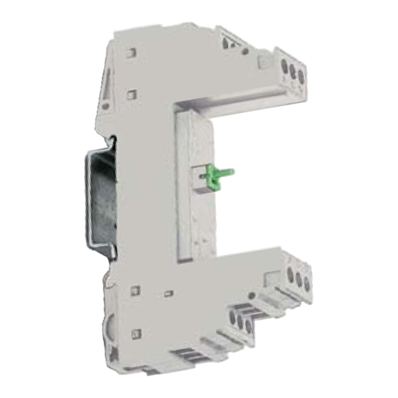
DE – Basiselement
EN – Base element
8 mm
Ø max. 1 ... 12
Ø min. 1 ... 12
DE – Am Basiselement werden alle ankommenden und weiterführenden Leitungen
angeschlossen. Der Metallfuss stellt beim Aufrasten auf die metallische Tragschiene
die Erdverbindung her. Die Schutzelemente sind im Steckteil integriert.
EN – All the incoming and outgoing conductors are connected to the base element. The
decoupling elements of the protective circuit are installed in the base element. The
contact to protective earth is made by snapping the metal foot onto the metal moun-
ting rail. The protection elements are integrated in the protective plug.
DE
Sicherheitshinweise
Beachten Sie bei der Montage die nationalen Vorschriften und Sicherheitsbestimmungen.
Vor der Montage ist das Basiselement auf äußere Beschädigung zu kontrollieren.
Wird eine Beschädigung oder ein anderer Mangel festgestellt, darf das Basiselement
nicht montiert werden.
Bei bestimmungswidrigen Eingriffen und Veränderungen am Gerät erlischt der
Gewährleistungsanspruch.
Potentialausgleich
Führen Sie die Verbindungsleitung vom Fußpunkt des Ableiters (Klemmen 3, 4 oder
Tragschiene) auf kürzestem Wege zum geerdeten Potentialausgleich der Anlage. Der
Potentialausgleich muss nach dem Stand der Technik ausgeführt sein.
Isolationsmessungen
Ziehen Sie vor einer Isolationsmessung in der Anlage das Steckteil, da sonst Fehlmes-
sungen möglich sind. Setzen Sie das Steckteil nach der Isolationsmessung wieder in
das Basiselement ein.
Anschluss
Die ankommenden ungeschützten Leitungen werden an den Eingangsklemmen 1,
3, 5, 7, 9 und 11 (IN) angeschlossen. Die Leitungen zum zu schützenden Gerät werden
an den Abgangsklemmen 2, 4, 6, 8, 10, 12 (OUT) angeschlossen.
In Kombination mit dem Basiselement eines Steckteils kommt es zu unterschiedlichen
Anschlussmöglichkeiten bei den Eingangs- und Ausgangsklemmen. Hierdurch kann ein
Leitungsschirm am Basiselement direkt oder indirekt auf Erde gelegt werden.
Die Klemmen 3 und 4 sind bei allen Basiselementen direkt mit dem metallischen Monta-
gefuß des Ableiters verbunden. Eine zusätzliche Verbindungsleitung zwischen den
Klemmen 3, 4 und der Tragschiene ist nicht erforderlich.
Hinweis:
Bei den Basiselementen 5SD7 512-1, 5SD7 522-1, 5SD7 500-0 und 5SD7
( )
3
4
( )
541-1 sind die Anschlüsse 9 und 10 (GND) direkt über den metallischen Mon-
tagefuß mit der Tragschiene verbunden.
9
10
Beim Basiselement 5SD7 522-0 sind die Anschlüsse 9 und 10 (GND) über
( )
3
4
( )
einen Gasableiter mit dem metallischen Montagefuß verbunden.
9
10
Safety
instructions
see back view
5SD7 512-1, 5SD7 522-1, 5SD7 522-0, 5SD7 541-1, 5SD7 500-0
0,5 Nm
8
2
10
4
OUT
6
12
8 mm
2
4 mm
2
0,2 mm
MLFB
Basiselement
5SD7 512-1
5SD7 522-1
5SD7 522-0
5SD7 541-1
5SD7 500-0
DE – Selbstkodierung des Basiselementes
EN – Self-coding of the base element
2
2,5 mm
2
0,2 mm
EN
Safety note
For mounting, please observe the national regulations and safety regulations.
Before assembly, the base element must be checked for external damage.
If damage or any other defect is detected, the base element must not be mounted.
The manufacturer's warranty no longer applies if the equipment is tampered with in any
way.
Equipotential bonding
Route the connecting conductor from the base point of the arrester (terminals 3, 4 or
DIN rail) along the shortest possible route to the grounded equipotential bonding of the
system. The equipotential bonding must be state-of-the-art.
Insulation measurements
Remove the plug before measuring the insulation in the plant, since otherwise faulty
measurements are possible. Replace the plug in the base element after the insulation
measurement.
Connection
The incoming unprotected lines are connected to the input terminals 1, 3, 5, 7, 9 and 11
(IN). The lines to the protected device are connected to the output terminals 2, 4, 6, 8, 10
and 12 (OUT).
In combination with the base element of a plug, there are various ways of connecting the
input and output terminals. As a result, a conductor shield on the base element can be
directly or indirectly connected to ground.
Terminals 3 and 4 are directly connected with the metallic mounting foot of the arrester
on all base elements. An additional connecting line between terminals 3, 4 and the DIN
rail is not necessary.
Note:
On base elements 5SD7 512-1, 5SD7 522-1, 5SD7 500-0 and 5SD7 541-1,
( )
3
4
( )
connections 9 and 10 (GND) are directly connected with the DIN rail via the
metallic mounting foot.
9
10
On base element 5SD7 522-0, connections 9 and 10 (GND) are connected to
( )
3
4
( )
the metallic mounting foot via a gas-filled surge arrester.
9
10
MLFB
Steckteil
• •
–
• •
–
–
• •
–
–
–
–
–
–
–
–
90
45
Z-NR: 9661727_00/31.07.08 Printed in Germany
253676.41.21 "01"
–
–
–
–
–
–
–
•
–
–
•
–
–
Publicidad

Resumen de contenidos para Siemens 5SD7 512-1
- Página 1 Klemmen 3, 4 und der Tragschiene ist nicht erforderlich. Note: Hinweis: On base elements 5SD7 512-1, 5SD7 522-1, 5SD7 500-0 and 5SD7 541-1, Bei den Basiselementen 5SD7 512-1, 5SD7 522-1, 5SD7 500-0 und 5SD7 connections 9 and 10 (GND) are directly connected with the DIN rail via the 541-1 sind die Anschlüsse 9 und 10 (GND) direkt über den metallischen Mon-...
- Página 2 Remarque : Medições do isolamento Dans le cadre des éléments de base 5SD7 512-1, 5SD7 522-1, 5SD7 500-0 et Antes de efectuar uma medição do isolamento na instalação, retire a peça macho, pois 5SD7 541-1, les raccordements 9 et 10 (GND) sont directement reliés avec le em caso contrário é...


