SOMFY FREEROLL RTS Manual De Instalación
Ocultar thumbs
Ver también para FREEROLL RTS:
- Guia de inicio rapido (2 páginas) ,
- Guia de inicio rapido (2 páginas)
Tabla de contenido
Publicidad
Idiomas disponibles
Idiomas disponibles
Enlaces rápidos
www.somfy.com
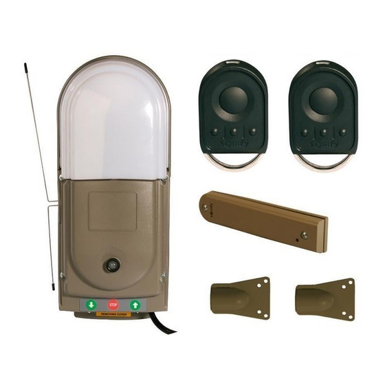
FREEROLL RTS
FR – Manuel d'installation
Récepteur de commande et de sécurité pour portes de
garage enroulables
EN – Installation Manual
Remote control system for rolling garage doors
DE – Montageanleitung
Empfänger
für
die
Steuerung
und
Sicherheit
von
Garagenrolltoren
ES – Manual de instalación
Receptor de mando y de seguridad para puertas de garaje
enrollables
Ref. 5053274A
01/2008
1
Publicidad
Capítulos
Tabla de contenido

Manuales relacionados para SOMFY FREEROLL RTS


Resumen de contenidos para SOMFY FREEROLL RTS
- Página 1 FREEROLL RTS FR – Manuel d’installation Récepteur de commande et de sécurité pour portes de garage enroulables EN – Installation Manual Remote control system for rolling garage doors DE – Montageanleitung Empfänger für Steuerung Sicherheit Garagenrolltoren ES – Manual de instalación...
-
Página 3: Tabla De Contenido
2. Position the TOP and BOTTOM Magnets on the door guide ............26 3. Door position..........................26 4. FREEROLL RTS: Fit the unit to the wall and wire the control unit ..........27 5. Wire and Fit the Safety Edge Transmitter..................27 6. -
Página 4: General Presentation
FREEROLL is a product that must be installed inside the garage with an integrated back-up control system (refer to the instructions of RDO CSI motors). Somfy hereby declares that the device is compliant with the essential demands and other relevant requirements of directive 1999/5/CE. -
Página 5: Type Of Door
RDO CSI motor. If the garage door opens on to a public road, we recommend the installation of a warning light, such as the Somfy orange warning light (ref. 9011084). Make sure that the door does not comprise of any accessible parts. -
Página 6: Quick Installation Guide
QUICK INSTALLATION GUIDE Warning ! From Step 1 to Step 3, you must use a test lead to operate the rolling garage door. Do not connect the FREEROLL control unit until the end-limits have been set. 1. Set Motor end-limits Set the UP and DOWN end-limits of the RDO CSI motor with a test lead (not-provided). -
Página 7: Freeroll Rts: Fit The Unit To The Wall And Wire The Control Unit
4. FREEROLL RTS: Fit the unit to the wall and wire the control unit . Fit the FREEROLL unit to wall. . Unplug the test lead from the motor. . Connect the 4-wires from the motor to the FREEROLL (refer to wiring diagram). -
Página 8: Full Installation
FULL INSTALLATION Warning! From Step 1 to Step 3, you must use a test lead to operate the rolling garage door. Do not connect the FREEROLL control unit until the end-limits have been set. Standard connections for right hand mount and rolling door cover internal garage mount. -
Página 9: Position The Top And Bottom Magnets On The Door Guide
2. Position the TOP and BOTTOM Magnets on the door guide Warning! Position the Magnets, the Safety Edge Transmitter and the FREEROLL control unit on the same side of the door Remove the Safety Edge Transmitter from the box. Back of the Back of the safety edge safety edge... -
Página 10: Door Position
4. FREEROLL RTS: Fit the unit to the wall and wire the control unit a. Wall mounting of the control unit Carefully remove the control unit from its box. Remove the light cover from the top of the unit by pressing in at the bottom on both sides (see arrows) and lifting it away from the unit. - Página 11 Take the two aerials from the packaging and connect them to the unit (See entry point and terminals in top left hand corner). Make sure that the aerials are not touching and that they po int in opposite directions (one up and one down parallel with the side of the control unit).
-
Página 12: Wire And Fit Wire The Safety Edge Transmitter
Re-connect the front cover buttons connector lead to the circuit board socket and the LED into the cover as illustrated in the pictures. Warning! The control buttons will not function correctly if the connector is connected the wrong way. NB: The cover LED connects to the white 3 pin terminal block on the printed circuit board. -
Página 13: Commission The Safety Edge
If the safety edge is active, the door will stop and reverse partially. If not, stop the door (STOP button) manually and please refer to the troubleshooting guide page 38. AT THIS STAGE OF THE INSTALLATION PROCESS, THE FREEROLL RTS CONTROL SYSTEM IS NOW READY-TO-USE. PROGRAMMING Warning! The remote controls provided with the kit are factory pre-programmed on the left first channel button. -
Página 14: Operating Test
OPERATING TEST 1. Use the remote controls cover LED flashing green « BIP » cover LED permanent amber cover LED flashing red cover LED permanent amber cover LED flashing green « BIP » 2. Obstacle detection function The detection of excessive weight during door opening will stop the door (anti-lift function) Warning! The torque of the motor must be selected according the size and weight of the rolling garage door. -
Página 15: Connecting Peripherals
CONNECTING PERIPHERALS 1. Description of the various peripherals Key Description Reference 230 V Integrated blinking Orange Warning Light 9011084 Reflex Photo-electric Cells 9013647 1841028 Key-switch 1841036 Alarm buzzer 9014397 2. Electrical connections for the various peripherals Warning! Switch off the electric power supply to the control unit before connecting any peripherals. - Página 16 Two types of connections can be made: Standard (without self test) With self test Push Switch 1 of the block DIP 1 to the ON position (PEC self-check software on; cf. Necessity to check correct functioning every 6 SETTINGS part page 37). months This means that an automatic test is conducted to check cell operation every time the door operates.
-
Página 17: Settings
SETTINGS RESET Warning! To validate and take into account the new settings for the Switch 1 of DIP1 and all the switches of DIP 2, press the RESET button on the top of the electronic board. Dip Switch Settings Standard operating mode DIP 1 PEC self-check software on (always Switch 1 ON... -
Página 18: Troubleshooting
TROUBLESHOOTING 1. System Status Indication The cover control unit LED indicates the status of the control unit and rolling door. The cover LED is a three-colour: RED, GREEN and AMBER lamp mounted on the front of the control unit. The status indications are detailed below: Door Positions Cover LED signal Status... -
Página 19: Program The Safety Edge Transmitter
System Status Cover LED signal and cause Solution A rapid RED, GREEN then AMBER single flash Load the transmitter on to the system as per the Indicates that a signal has been received "Programming” page 39 from a transmitter that has not been loaded onto the system. - Página 20 3. Push and hold the CLOSE (down) button, the cover LED will go: Warning! Release the button WHILE the LED is SOLID GREEN FLASHING RED - SOLID RED (5 sec) - SOLID AMBER (2 sec) - SOLID GREEN (2 sec). The Safety Edge Transmitter is deleted.
-
Página 21: Technical Specifications
TECHNICAL SPECIFICATIONS FREEROLL RTS control unit Power supply 220-240 Vac / 50 Hz Fuse T6.3AH 250V Motor power 230 Vac 5A Protection rating IP20 Ambient operation temperature -20 to +70 °C Radio frequency RTS 433,42 MHz Safety Input Yes - 1 for photocells... -
Página 23: Índice
2. Fijación de los imanes SUPERIOR e INFERIOR a la guía de la puerta ........66 3. Colocación de la puerta en posición....................66 4. Fijación del receptor FREEROLL RTS a la pared y cableado............67 5. Conexión y fijación del emisor de barra sensible ................67 6. -
Página 24: Aspectos Generales
El producto FREEROLL debe instalarse en el interior del garaje con un sistema de mando de emergencia integrado (consulte las instrucciones de los motores RDO CSI). Somfy declara que este producto cumple los requisitos básicos y demás disposiciones pertinentes de la directiva 1999/5/CE. -
Página 25: Ámbito De Aplicación
2. Ámbito de aplicación Puertas de garaje enrollables para uso residencial. PUNTOS QUE DEBEN VERIFICARSE ANTES DE LA INSTALACIÓN 1. Controles preliminares No moje el dispositivo. No instale el FREEROLL en un lugar donde exista riesgo de caída de agua. La parte baja de la puerta debe incorporar una barra sensible de seguridad compatible con el sistema FREEROLL. -
Página 26: Guía De Instalación Rápida
GUÍA DE INSTALACIÓN RÁPIDA Atención: del paso 1 al paso 3, es obligatorio utilizar un cable de ajuste para controlar la puerta de garaje enrollable. El receptor FREEROLL no está conectado a la corriente. 1. Ajuste de los finales de carrera del motor Ajuste los finales de carrera SUPERIOR e INFERIOR del motor RDO CSI con el cable de ajuste (no incluido). -
Página 27: Fijación Del Receptor Freeroll Rts A La Pared Y Cableado
. Vuelva a abrir la puerta completamente pulsando el botón . Pulse el botón de la tapa para cerrar la puerta completamente y probar el buen funcionamiento de la barra sensible simulando un obstáculo. EN ESTE ESTADIO DE LA INSTALACIÓN, EL RECEPTOR FREEROLL RTS ESTÁ LISTO PARA FUNCIONAR. -
Página 28: Guía De Instalación Completa
GUÍA DE INSTALACIÓN COMPLETA Atención: del paso 1 al paso 3, es obligatorio utilizar un cable de ajuste para controlar la puerta de garaje enrollable. El receptor FREEROLL no está conectado a la corriente. Las conexiones estándar para el montaje del motor a la derecha y la caja dentro son: Negro: cierre Azul: neutro... -
Página 29: Fijación De Los Imanes Superior E Inferior A La Guía De La Puerta
2. Fijación de los imanes SUPERIOR e INFERIOR a la guía de la puerta. Atención: sitúe los imanes, el emisor de barra sensible y el receptor FREEROLL en el mismo lado de la puerta. Placa Plaque de Plaque de fijación del fixation de fixation de Sitúe la placa de fijación del emisor de barra sensible en la... -
Página 30: Colocación De La Puerta En Posición
Aimant Aimant Imán INFERIOR 4. Fijación del receptor FREEROLL RTS a la pared y cableado a. Montaje en pared del receptor Saque el receptor del embalaje con mucho cuidado. Quite la cubierta de protección superior de la luz integrada presionando sobre su base por ambos lados (como se indica con las flechas de la imagen). - Página 31 Saque las dos antenas del embalaje y atorníllelas al receptor (en la foto de la izquierda pueden verse las antenas y el conector en la parte superior izquierda de la tarjeta electrónica). Asegúrese de que las dos antenas no se tocan, de que no se cruzan y de qu e apuntan en direcciones opuestas (una hacia arriba y otra hacia abajo pero ambas paralelas a un lado del producto).
-
Página 32: Conexión Y Fijación Del Emisor De Barra Sensible
Conecte con precaución el cable plano de los botones de mando exteriores a la regleta de bornes de la tarjeta electrónica y vuelva a introducir el indicador luminoso en la tapa tal y como se indica en las fotos. Atención: si el cable plano de los botones exteriores se conecta en el sentido equivocado, los botones exteriores no funcionarán bien. -
Página 33: Aprendizaje De La Barra Sensible
Si se activa la barra sensible, la puerta se para y se reabre parcialmente. Si esto no ocurre, detenga la puerta (botón STOP) y consulte la guía de diagnóstico página 77. EN ESTE ESTADIO DE LA INSTALACIÓN, EL RECEPTOR FREEROLL RTS ESTÁ LISTO PARA FUNCIONAR. PROGRAMACIÓN Atención: los mandos a distancia suministrados con el kit vienen preconfigurados de fábrica... -
Página 34: Prueba De Funcionamiento
PRUEBA DE FUNCIONAMIENTO 1. Utilización de los mandos a distancia Indicador luminoso exterior verde intermitente Indicador luminoso exterior naranja fijo Indicador luminoso exterior rojo intermitente Indicador luminoso exterior naranja fijo Indicador luminoso exterior verde intermitente "BIP" 2. Funcionamiento de la detección de obstáculos La detección de un sobrepeso durante la apertura detiene la puerta (función anti-lift). -
Página 35: Conexión De Los Periféricos
CONEXIÓN DE LOS PERIFÉRICOS 1. Descripción de los distintos periféricos Rep. Descripción Referencia Luz naranja 230 V con intermitente integrado 9011084 Células réflex 9013647 1841028 Interruptor con llave 1841036 Timbre de alarma 9014397 2. Conexión eléctrica de los distintos periféricos Atención: desconecte el receptor de la corriente eléctrica antes de realizar cualquier intervención en los periféricos. - Página 36 Existe la posibilidad de hacer dos tipos de conexión: Estándar (sin auto-test) Con auto-test Ponga el interruptor 1 del bloque DIP 1 del receptor en la posición ON (Células réflex activas; ver CONFIGURACIÓN DE PARÁMETROS página 76). Hay que comprobar su buen funcionamiento Se realiza un test automático para comprobar el buen cada seis meses funcionamiento de las células cada vez que se acciona...
-
Página 37: Configuración De Parámetros
CONFIGURACIÓN DE PARÁMETROS Atención: para tener en cuenta y validar los nuevos RESET parámetros del interruptor 1 de DIP1 y de los cuatro interruptores de DIP 2, pulse el botón RESET de la tarjeta electrónica. Modo de funcionamiento Parámetros interruptor Dip estándar DIP 1 Células réflex activas (debe... -
Página 38: Diagnóstico
DIAGNÓSTICO 1. Indicaciones de funcionamiento del sistema Las indicaciones de funcionamiento de la puerta las facilita el indicador luminoso exterior del receptor. Puede ponerse de tres colores: ROJO, VERDE y NARANJA. Las indicaciones de funcionamiento se detallan a continuación. Posiciones de la puerta Indicador luminoso exterior Estado VERDE FIJO... -
Página 39: Configuración Del Emisor De Barra Sensible
Estados del sistema Indicaciones del indicador luminoso Solución exterior y causas PARPADEO ÚNICO EN ROJO, VERDE Y NARANJA RÁPIDO Configure el emisor conectándolo al receptor Indica que se ha recibido una señal de un siguiendo el procedimiento descrito en la página 78. emisor que no está... - Página 40 3. Pulse de manera sostenida el botón DESCENSO hasta que el indicador luminoso cambie a VERDE FIJO el indicador luminoso exterior pasara por la siguiente secuencia: ROJO INTERMITENTE – ROJO FIJO (5 seg.) – NARANJA FIJO (2 seg. – VERDE FIJO (2 seg.) el indicador luminoso exterior se pondrá...
-
Página 41: Características Técnicas
CARACTERÍSTICAS TÉCNICAS Receptor FREEROLL RTS Alimentación 220-240 VCA/50 Hz Fusible T6.3AH 250V Potencia del motor 230 VCA 5A Índice de protección IP20 Temperatura ambiente de funcionamiento -20° C a +70 °C Frecuencia de radio RTS 433,42 MHz Entrada de seguridad Sí... - Página 43 NOTES...
- Página 44 Somfy SAS dans un souci constant d’évolution et d’amélioration peut modifier le produit sans préavis. Photos non contractuelles. Somfy SAS in a constant concern of evolution and improvement may modify the product without prior notice. Non contractual pictures. Somfy SAS, capital 20.000.000 Euros, RCS Bonneville 303.970.230 01/2008...