Tabla de contenido
Publicidad
Idiomas disponibles
Idiomas disponibles
Enlaces rápidos
12" (305 mm)
Dovetail jig
Gabarit de queues d'aronde
de 305 mm (12 po)
Guí de 305 mm (12 pulg)
para cola de milano
Instruction manual
Manuel d'instructions
Manual de'instrucciones
Française : Page 28
Español: Página 53
www.deltaportercable.com
INSTRUCTIVO DE OPERACIÓN, CENTROS
DE SERVICIO Y PÓLIZA DE GARANTÍA.
LÉASE ESTE INSTRUCTIVO
ANTES DE USAR EL PRODUCTO.
4210
4212
4216
Publicidad
Tabla de contenido
Solución de problemas

Manuales relacionados para Porter Cable 4210


Resumen de contenidos para Porter Cable 4210
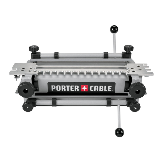
- Página 1 Guí de 305 mm (12 pulg) para cola de milano Instruction manual Manuel d'instructions Manual de'instrucciones Française : Page 28 Español: Página 53 www.deltaportercable.com INSTRUCTIVO DE OPERACIÓN, CENTROS 4210 DE SERVICIO Y PÓLIZA DE GARANTÍA. LÉASE ESTE INSTRUCTIVO 4212 ANTES DE USAR EL PRODUCTO. 4216...
-
Página 2: Tabla De Contenido
TABLE OF CONTENTS SAFETY GUIDELINES IMPORTANT SAFETY INSTRUCTIONS ADDITIONAL SPECIFIC SAFETY RULES BACKGROUND INFORMATION Dovetail and Box Joint Overview Product Capabilities 4200 Series Dovetail Jig Overview Carton Contents Assembly Additional Tools Required Mounting Instructions OPERATION Clamps Template Mounting Template Support Positioning the Wood Half-Pins Vs. -
Página 3: Safety Guidelines
SAFETY GUIDELINES - DEFINITIONS This manual contains in for ma tion that is im por tant for you to know and un der stand. This in for ma tion re lates to pro- tect ing YOUR SAFE TY and PRE VENT ING EQUIP MENT PROB LEMS. To help you rec og nize this in for ma tion, we use the symbols to the left. -
Página 4: Additional Specific Safety Rules
16. AVOID UNINTENTIONAL STARTING. Do not carry a plugged-in tool with finger on switch. Be sure switch is off when plugging in. Keep hands, body and clothing clear of blades, bits, cutters, etc. when plugging in the tool. 17. OUTDOOR USE EXTENSION CORDS. When tool is used outdoors, use only extension cords marked “Suitable for use with outdoor appliances –... - Página 5 THROUGH DOVETAILS Tails Pins HALF-BLIND DOVETAILS RABBETED HALF-BLIND DOVETAILS BOX (FINGER) JOINT A similar joint, called a box or finger joint, has straight protrusions called fingers on both boards. This joint is used on jewelry boxes and other small boxes. The box joint is strong because it has a large surface area for glue.
-
Página 6: Product Capabilities
Accessory Kit - includes the template, router bit, and templet guide included with the model 4210. 4213 Accessory kit - incudes all items necessary to provide the 4210 jig with the same capabilities as the 4212 deluxe dovetail jig. 4215 Accessory kit - contains the template, router bits, and templet guides to make miniature through dovetails and half-blind dovetails. -
Página 7: Carton Contents
CARTON CONTENTS DOVETAIL JIGS 4210 4212 Base Base Half-blind & Sliding Dovetail Template Half-blind & Sliding Dovetail Template Through & Box Template Dovetail Bit Dovetail Bit Template Guide Straight Bit Lock nut Template Guide (2) T-handle Hex Wrench Lock Nuts (2) -
Página 8: 4200 Series Dovetail Jig Overview
ACCESSORY KITS 4211 4213 4215 Half-blind & Sliding Dovetail Through and Box Joint 1. Miniature Half-blind, Through, & Template Template Box Template Brackets (2) Brackets (2) 2. Brackets (2) Dado Depth Bracket Half-Blind Depth Bracket 3. Template Guide and Lock Nut (2) Half-blind Depth Bracket Straight Bit 4. -
Página 9: Additional Tools Required
must accept the Porter-Cable template guides supplied with the jig. (Adapters and sub-bases are available for most routers.) must have a 1/2" collet for use with 4210 and 4212 jigs and the 4211 and 4213 accessory kits. ... -
Página 10: Clamps
CLAMPS The 4200 series jigs are equipped with two cam-action clamps (A) Fig. C1 with knobs (B) to adjust for workpiece thickness, and levers (C) for quick clamping and releasing of workpieces. NOTE: Use a scrap board (A) Fig. C2 to prevent misalignment (A) Fig. C3. TEMPLATE MOUNTING You can mount the templates in two positions on the jig(s) which allows the production of multiple types of joints with each template. -
Página 11: Template Support
TEMPLATE SUPPORT For every type of joint, place wood in the top clamp, whether a workpiece or a scrap piece, to provide support for the router on the template. You can add extra support by inserting a second board (A) Fig. E1 (of the same thickness) in the top clamp to ensure that the template is parallel to the base across its length. -
Página 12: Half-Pins Vs. Half-Tails
HALF-PINS VS. HALF-TAILS Traditionally, dovetails have half-pins cut on both ends (Fig. G1). Half-tails will be just as strong, but will not be as attractive (Fig. G2). If your joints are half-tails and you want half-pins, move the vertical board 1/2" either left or right, then move the horizontal board accordingly. -
Página 13: Template Guides
TEMPLATE GUIDES Use the correct template guides provided with this unit to guide the router against the template fingers. To determine the proper guide for a given joint, place the template guide in the slot on the left side of the corresponding template. The guide should have a snug fit in the slot. -
Página 14: Wood Preparation
WOOD PREPARATION Properly preparing the materials for your project is the key to good-looking and tight-fitting joints. You must cut your wood at perfect right angles (Fig. L1). Cuts that are off even one degree will not align correctly (Fig. L2). Also, your workpieces must be flat and not cupped. -
Página 15: Project Layout
PROJECT LAY OUT Keeping track of the outer and inner face of each workpiece and how the different parts mate with each other is very important. Step 1 - Lay out the workpieces face down and label the inside faces with an “I” (Fig. N1). Step 2 - Label the corners “A”, “B”, “C”, and “D”... -
Página 16: Basic Joints
Use two routers (if possible) - one for the pins and the other for the tails - to make the process quicker and easier. If you are using the 4210 dovetail jig, you will need the 4213 accessory kit to make this joint. ITEMS NEEDED... -
Página 17: Cutting The Pins
Step 4 - Reposition the offset guide (A) Fig. P4 flush to the vertical board and secure it. Step 5 - Reposition the scrap board(A) Fig. P5 so that it is flush with the rear edge of the vertical board (B). Step 6- Align the template using the “tails/box”... -
Página 18: Fitting And Troubleshooting
Step 5- Rout between the fingers of the template (Fig. P12). Step 6 - Remove the pin board and check the fit with the tailboard (Fig. P13). THROUGH DOVETAIL TROUBLESHOOTING For joints that are too loose, move the template toward you slightly. For joints that are too tight, move the template away from you slightly. -
Página 19: Fitting And Troubleshooting
Clamp the tailboard (drawer side) in lower clamp (vertical Step 4 - position) on the left side of the base with the outside of the board CENTER facing the jig (A) Fig. Q3. Step 5 - Center the board between the farthest finger on the left and the nearest finger on the right of the board. -
Página 20: Half-Blind Dovetail With A Lipped Front
RABBETED HALF-BLIND DOVETAILS To produce rabbeted half-blind dovetails (drawer front), cut the pins for a half-blind joint after the drawer front has been rabbeted. The depth of the rabbet must be deeper than the half-blind router bit depth guide. NOTE: Cut the tails first. -
Página 21: Cutting The Pins
Step 7 - Mount the dovetail bit and template guide to the router and set the router bit depth using the “half-blind” bit depth guide (Fig. R6). Step 8 - Make a climb-cut from right to left across the outer edge of the tail board to reduce tear-out (Fig. R7). Step 9 - Rout in and out of the fingers of the template from left to right (Fig. -
Página 22: Box Joints
NOTE: If you are using the 4210 dovetail jig, you will need the 4213 accessory kit to make this joint. You will need the 4215 accessory kit for the miniature box joints. Box joint fingers are spaced in 1" increments (1/2" for miniature). -
Página 23: Cutting The Second Workpiece
Step 4 - Reposition the left offset guide (A) Fig. S4 flush against the workpiece (B). Step 5 - Align the template, using the “tails/Box” template line with the line formed where the scrap board and the workpiece meet. Step 6 - Mount the straight bit and template guide on the router and set the router bit depth using the “tails/box”... -
Página 24: Sliding Dovetails
( 1/4", 3/8" and 1/2"), but you can manually set your router bit depth to any setting. NOTE: Be certain that the router bit will not cut into the base or offset guides during this cut.Everything is provided for this cut in both the 4210 and 4212 jigs. ITEMS NEEDED Dado Template ●... -
Página 25: Tenon Board
Step 4 - Set your router bit depth by using either of the three choices (A, B, or C) Fig. T3 on the left side of the template, or by manually setting the router to another depth. Step 5 - Slowly rout along the slot from left to right (Fig. -
Página 26: Maintenance
Customer Care Center at 1-888-848-5175 to receive personalized support from highly-trained technicians. FREE WARNING LABEL REPLACEMENT If your warning labels become illegible or are missing, call 1-800-223-7278 for a free replacement. Model 4210 TO REDUCE THE RISK OF INJURY, USER 12" Dovetail Jig MUST READ INSTRUCTION MANUAL BEFORE OPERATING PRODUCT. -
Página 27: Warranty
WARRANTY PORTER-CABLE will repair, without charge, any defects due to faulty materials or workmanship for three years from the date of purchase. This warranty does not cover part failure due to normal wear or tool abuse. For further detail of warranty coverage and warranty repair information, visit www.deltaportercable.com or call (888) 848-5175. -
Página 28: Mesures De Sécurité - Définitions
La Porter-Cable recommande avec force que ce produit n'ait pas modifié et/ou utilisé pour l'application autrement que pour lequel il a été conçu.If you have any questions relative to its application DO NOT use the product until you have written Porter Cable and we have advised you. -
Página 29: Précautions Supplémentaires
16. ÉVITEZ LA MISE EN MARCHE ACCIDENTELLE. Ne transportez pas un outil branché avec le doigt appuyé sur l’interrupteur. Assurez-vous que l’interrupteur est en position d’arrêt avant de brancher l’outil. Tenez les mains, le corps et les vêtements à l’écart des lames, mèches, couteaux, etc., en branchant l’outil. 17. - Página 30 JOINTS EN QUEUES D'ARONDE TRAVERSANTES Queues Tenons JOINTS EN QUEUES D'ARONDE SEMI-AVEUGLES JOINTS EN QUEUES D'ARONDE SEMI-AVEUGLES AVEC UNE PARTIE AVANT À REBORD JOINT À EMBOÎTEMENT (JOINT À QUEUES DROITES) Un joint similaire, appelé joint à emboîtement ou joint à queues droites, est pourvu de protubérances droites appelées «...
- Página 31 Kit d'accessoires - comprend le gabarit, la mèche de défonceuse et le guide de gabarits qui accompagnent le modèle standard 4210. 4213 Kit d'accessoires - comprend tous les instruments nécessaires pour conférer à l'appareil 4210 les mêmes capacités que l'appareil à queues d'aronde supérieur 4212. 4215 Kit d'accessoires - comprend le gabarit, les mèches de défonceuse et les guides de gabarits...
-
Página 32: Contenu Du Carton
CONTENU DU CARTON APPAREILS À QUEUES D'ARONDE 4210 4212 1. Embase Embase 2. Gabarit pour queues d'aronde semi-aveugles et lambris Gabarit pour queues d'aronde semi-aveugles et lambris 3. Gabarit pour queues d'aronde traversantes et joints à Mèche à queues d'aronde emboîtement... -
Página 33: Ajustement De Taille
KITS D'ACCESSOIRES 4211 4213 4215 Gabarit pour queues d'aronde Gabarit pour queues d'aronde Gabarit pour joints à semi-aveugles et lambris traversantes et joints à emboîtement et queues d'aronde Supports (2) emboîtement traversantes et semi-aveugles en Support de profondeur pour Supports (2) miniature lambris Support de profondeur pour... -
Página 34: Instructions Pour Le Montage
à pince de 1/2 po pour emploi avec les appareils 4210 et 4212, ainsi qu'avec les kits d'accessoires 4211 et 4213. 4211 and 4213 accessory kits. doit avoir un mandrin à pince de 1/4 po pour emploi avec le kit ... -
Página 35: Brides De Fixation
UTILISATION Montez correctement votre pièce à travailler sur l'appareil. Si la pièce à travailler n'est pas solidement en place, elle risque d'être endommagée lorsqu'elle sera déplacée. Les appareils utilisent deux positions de montage pour les pièces à travailler - une position horizontale et une position verticale. - Página 36 SUPPORT DES GABARITS Pour chaque type de joint, placez du bois dans la bride du haut, soit une pièce à travailler, soit un morceau de bois sans valeur supplémentaire, afin de fournir un support pour la défonceuse sur le gabarit. Vous pouvez ajouter un soutien supplémentaire en insérant une deuxième planche (A, sur la Fig.
- Página 37 DEMI-TENONS OU DEMI-QUEUES Traditionnellement, les joints en queues d'aronde ont des entailles de type demi-tenon aux deux extrémités (Fig. G1). Des demi-queues seront tout aussi solides, mais elles ne seront pas aussi plaisantes sur le plan esthétique (Fig. G2). Si vos joints ont des demi-queues et si vous voulez des demi-tenons, déplacez la planche verticale de 1/2 po vers la gauche ou vers la droite, puis faites glisser la planche horizontale en conséquence.
-
Página 38: Guides De Gabarits
GUIDES DE GABARITS Utilisez les guides de gabarits corrects qui sont fournis avec cet appareil pour guider la défonceuse contre les queues droites du gabarit. Pour déterminer le guide correct pour un joint donné, placez le guide de gabarit dans la fente située sur le côté gauche du gabarit correspondant. - Página 39 PRÉPARATION DU BOIS Une préparation correcte des matériaux pour vos projets est la clé du succès pour produire des joints bien ajustés et d'une esthétique agréable. Vous devez couper votre bois à des angles droits parfaits (Fig. L1). Les coupes qui sont inexactes ne serait-ce que d'un seul degré...
- Página 40 CONFIGURATION DES PROJETS Il est très important de toujours suivre la surface extérieure et la surface intérieure de chaque pièce à travailler, ainsi que la façon dont les différents composants s'emboîtent les uns dans les autres. Placez les pièces à travailler face orientée vers le bas et étiquetez les surfaces intérieures avec la lettre «...
-
Página 41: Joints De Base
Utilisez deux toupies (si possible), une pour les goupilles et l’autre pour les queues d’aronde afin d’accélérer et de faciliter le processus. Si vous utilisez le gabarit de montage pour queue d’aronde 4210, il vous faudra utiliser la trousse d’accessoires 4213 pour effectuer ce joint. - Página 42 4. Repositionnez le guide excentré (A, sur la Fig. P4) de façon à ce qu'il repose contre la planche verticale et assujettissez- 5. Repositionnez le morceau de bois supplémentaire (A, sur la Fig. P5) de façon à ce qu'il repose contre le bord arrière de la planche verticale (B).
- Página 43 Coupez entre les queues droites du gabarit (Fig. P12). Retirez la planche à tenons et assurez-vous que cette planche est bien ajustée par rapport à la planche à queues (Fig. P13). RÉSOLUTION DES PROBLÈMES CONCERNANT LES QUEUES D'ARONDE TRAVERSANTES Pour les joints qui ne sont pas suffisamment serrés, faites glisser légèrement le gabarit en le rapprochant de vous. Pour les joints qui sont trop serrés, faites glisser légèrement le gabarit en l'éloignant de vous.
- Página 44 Bridez la planche à queues (côté du tiroir) dans la bride du bas (position verticale) sur le côté gauche de l'embase, avec l'extérieur de la planche CENTRER faisant face à l'appareil (A, sur la Fig. Q3). Centrez la planche entre la queue droite la plus éloignée vers la gauche et la queue droite la plus proche vers la droite de la planche.
- Página 45 QUEUES D'ARONDE SEMI-AVEUGLES AVEC UNE PARTIE AVANT À REBORD Pour produire des avants de tiroir, coupez les goupilles après que l'avant de tiroir ait été découpé en tranches. La profondeur de la tranche doit être plus profonde que le guide de profondeur. REMARQUE Coupez les queues en premier.
- Página 46 Montez la mèche à queues d'aronde et le guide de gabarit sur la défonceuse, et ajustez la profondeur de pénétration de la mèche de la défonceuse en utilisant le guide de profondeur de la mèche « semi-aveugle » (Fig. R6). Faites une «...
-
Página 47: Coupe De La Première Pièce À Travailler
REMARQUE Si vous utilisez l'appareil à queues d'aronde 4210, vous aurez besoin du kit d'accessoires 4213 pour produire ce joint. Vous aurez besoin du kit d'accessoires 4215 pour les joints à emboîtement en miniature. -
Página 48: Coupe De La Deuxième Pièce À Travailler
Repositionnez le guide excentré de gauche de façon à ce qu'il repose contre la pièce à travailler. Alignez le gabarit en utilisant la ligne de gabarit « queues/ emboîtement » avec l'intersection du morceau de bois supplémentaire et de la pièce à travailler. Montez la mèche droite et le guide de gabarit sur la défonceuse, et ajustez la profondeur de pénétration de la mèche de la défonceuse en utilisant le guide de profondeur de la mèche «... - Página 49 REMARQUE Assurez-vous que la mèche de la défonceuse ne pénétrera pas dans l'embase ou dans les guides excentrés pendant cette coupe. Les appareils 4210 et 4212 contiennent tout ce qu'il faut pour cette coupe. PIÈCES NÉCESSAIRES Gabarit pour joint à...
-
Página 50: Coupe De Planches À Tenons
4. Ajustez la profondeur de pénétration de la mèche de votre défonceuse en utilisant l'une des trois options (A, B, ou C, sur la Fig. T3) sur le côté gauche du gabarit, ou en réglant manuellement la défonceuse sur une autre profondeur. 5. -
Página 51: Guide De Depannage
REMPLACEMENT GRATUIT DE L'ETIQUIETTE Si les étiquettes d’avertissement deviennent illisibles ou sont manquantes, composer le (888) 848-5175 pour en obtenir le remplacement gratuit. Model 4210 TO REDUCE THE RISK OF INJURY, USER 12" Dovetail Jig MUST READ INSTRUCTION MANUAL BEFORE OPERATING PRODUCT. -
Página 52: Garantie Limitée De Trois Ans
GARANTIE LIMITÉE DE TROIS ANS PORTER-CABLE réparera, sans frais, tout produit défectueux causé par un défaut de matériel ou de fabrication pour une période de trois ans à compter de la date d’achat. La présente garantie ne couvre pas les pièces dont la défectu- osité... -
Página 53: Pautas De Seguridad/Definiciones
PAUTAS DE SEGURIDAD/DEFINICIONES Es importante para usted leer y entender este manual. La información que lo contiene relaciona a proteger SU SEGURIDAD y PREVENIR los PROBLEMAS. Los símbolos debajo de son utilizados para ayudarlo a reconocer esta información. Indica una situación de inminente riesgo, la cual, si no es evitada, causará la muerte o lesiones serias. Indica una situación potencialmente riesgosa, que si no es evitada, podría resultar en la muerte o lesiones serias. -
Página 54: Normas De Seguridad Adicionales
16. EVITE EL ARRANQUE NO INTENCIONADO. No transporte una herramienta enchufada con el dedo en el interruptor. Asegúrese de que el interruptor esté en la posición de apagado cuando enchufe la herramienta. Mantenga las manos, el cuerpo y la ropa alejados de las hojas, las brocas, los cortadores, etc., cuando enchufe la herramienta. 17. -
Página 55: Junta De Caja (Dedos)
COLAS DE MILANO PASANTES Tails Pins COLAS DE MILANO SEMICIEGAS COLAS DE MILANO SEMICIEGAS CON UNA PARTE DELANTERA CON REBORDE JUNTA DE CAJA (DEDOS) Una junta similar, denominada junta de caja o de dedos, tiene salientes rectos llamados dedos en ambas tablas. -
Página 56: Capacidades Del Producto
Juego de accesorios: incluye la plantilla, la broca de fresadora y la guía de plantilla incluidas con el modelo 4210. 4213 Juego de accesorios: incluye todos los artículos necesarios para proporcionar al posicionador 4210 las mismas capacidades que el posicionador para colas de milano de lujo 4212. 4215 Juego de accesorios: contiene la plantilla, las brocas de fresadora y las guías de plantilla para hacer... -
Página 57: Contenido De La Caja De Cartón
CONTENIDO DE LA CAJA DE CARTÓN POSICIONADORES PARA COLAS DE MILANO 4210 4212 Base Base Plantilla para colas de milano semiciegas y de mortaja Plantilla para colas de milano semiciegas y de mortaja Plantilla para colas de milano pasantes y juntas de caja... -
Página 58: Juegos De Accesorios
JUEGOS DE ACCESORIOS 4211 4213 4215 1. Plantilla para colas de milano 1. Plantilla para colas milano 1. Plantilla para colas de milano semiciegas y de mortaja pasantes y juntas de caja semiciegas, colas de milano pasantes 2. Soportes (2) 2. -
Página 59: Herramientas Adicionales Necesarias
(Hay adaptadores y subbases disponibles para la mayoría de fresadoras.) debe tener un portaherramienta de 1/2" para utilizarse con los posicionadores 4210 y 4212, y los juegos de accesorios 4211 y 4213. debe tener un portaherramienta de 1/4" para utilizarse con el juego de accesorios 4215 NOTA: Aunque los posicionadores y los juegos de accesorios incluyen las brocas de fresadora y las guías de... -
Página 60: Utilización
UTILIZACIÓN Monte correctamente la pieza de trabajo en el posicionador. Si la pieza de trabajo no está sujeta firmemente, se puede dañar cuando se mueva. Los posicionadores utilizan dos posiciones de montaje para las piezas de trabajo: horizontal y vertical. Algunas juntas requieren ambas posiciones, mientras que otras requieren el uso de una tabla de desecho en posición horizontal (abrazadera superior) y la pieza de trabajo en posición vertical (abrazadera inferior). -
Página 61: Soporte De Las Plantillas
SOPORTE DE LAS PLANTILLAS Para cada tipo de junta, coloque madera en la abrazadera superior, tanto si se trata de una pieza de trabajo como si se trata de un pedazo de desecho, con el fin de proporcionar soporte para la fresadora sobre la plantilla. Se puede añadir soporte adicional insertando una segunda tabla (A) Fig. -
Página 62: Medias Espigas Frente A Medias Colas
MEDIAS ESPIGAS FRENTE A MEDIAS COLAS Tradicionalmente, las colas de milano tienen medias espigas cortadas en ambos extremos (Fig. G1). Las medias colas serán igual de fuertes, pero no serán tan atractivas (Fig. G2). Si las juntas son medias colas y usted quiere medias espigas, mueva la tabla vertical 1/2"... -
Página 63: Guías De Plantilla
GUÍAS DE PLANTILLA Use las guías de plantilla correctas suministradas con esta unidad para guiar la fresadora contra los dedos de la plantilla. Para determinar la guía apropiada para una junta dada, coloque la guía de plantilla en la ranura ubicada en el lado izquierdo de la plantilla correspondiente. -
Página 64: Preparación De La Madera
PREPARACIÓN DE LA MADERA La preparación apropiada de los materiales para el proyecto que usted va a realizar es la clave para lograr juntas que luzcan bien y encajen firmemente. Usted debe cortar la madera en ángulos rectos perfectos (Fig. L1). Los cortes que estén desviados incluso un grado no se alinearán correctamente (Fig. -
Página 65: Disposición Del Proyecto
DISPOSICIÓN DEL PROYECTO Es muy importante dar seguimiento a la cara exterior y la cara interior de cada pieza de trabajo y cómo las distintas partes encajan unas con otras. Paso 1: Extienda las piezas de trabajo con la cara orientada hacia abajo y marque las caras interiores con una "I"... -
Página 66: Colas De Milano Pasantes
Si usted está usando el posicionador para colas de milano 4210, necesitará el juego de accesorios 4213 para hacer esta junta. ARTÍCULOS NECESARIOS PARA COLAS ARTÍCULOS NECESARIOS... -
Página 67: Corte De Las Espigas
Paso 4 - Reposicione la guía excéntrica (A) Fig. P4 al ras con la tabla vertical y sujétela firmemente. Paso 5 - Reposicione la tabla de desecho (A) Fig. P5 de modo que quede al ras con el borde trasero de la tabla vertical (B). -
Página 68: Resolución De Problemas Para Colas De Milano Pasantes
Paso 4- Frese entre los dedos de la plantilla (Fig. P12). Paso 5 - Retire la tabla de espigas y compruebe el encaje con la tabla de colas (Fig. P13). RESOLUCIÓN DE PROBLEMAS PARA COLAS DE MILANO PASANTES En el caso de juntas que estén demasiado flojas, mueva la plantilla ligeramente hacia usted. En el caso de juntas que estén demasiado apretadas, mueva la plantilla alejándola ligeramente de usted. -
Página 69: Ajuste Y Resolución De Problemas
Paso 4 - Fije la tabla de colas (lado del cajón) en la abrazadera inferior (posición vertical) ubicada en el lado izquierdo de la base, con el exterior de la CENTRO tabla orientado hacia el posicionador (A) Fig. Q3. Paso 5 - Centre la tabla entre el dedo más alejado ubicado a la izquierda y el dedo más cercano ubicado a la derecha de la tabla. -
Página 70: Colas De Milano Semiciegas Con Una Parte Delantera Con Reborde
COLAS DE MILANO SEMICIEGAS CON UNA PARTE DELANTERA CON REBORDE Para producir un frente del cajón, corte los pernos después de que se haya rebanado el frente del cajón. La profundidad de la rebanada debe ser más profunda que la guía de la profundidad. - Página 71 Paso 7 - Monte la broca para colas de milano y la guía de plantilla en la fresadora y ajuste la profundidad de la broca de fresadora utilizando la guía de profundidad de la broca para colas de milano "semiciegas" (Fig. R6).
-
Página 72: Juntas De Caja
NOTA: Si usted está usando el posicionador para colas de milano 4210, necesitará el juego de accesorios 4213 para hacer esta junta. Necesitará el juego de accesorios 4215 para las juntas de caja miniatura. -
Página 73: Corte De La Segunda Pieza De Trabajo
Paso 4 - Reposicione la guía excéntrica izquierda (A) Fig. S8 al ras contra la pieza de trabajo (B). Paso 5 - Alinee la plantilla, usando la línea de la plantilla para "colas/caja", con la intersección de la tabla de desecho y la pieza de trabajo. -
Página 74: Colas De Milano Deslizantes
NOTA: Asegúrese de que la broca de fresadora no corte en la base ni en las guías excéntricas durante la realización de este corte.Se proporciona todo lo necesario para realizar este corte tanto en los posicionadores 4210 como 4212. ARTÍCULOS NECESARIOS Plantilla para mortajas ●... -
Página 75: Mantenimiento
Paso 4 - Ajuste la profundidad de la broca de fresadora utilizando cualquiera de las tres opciones (Fig. T3) ubicadas en el lado izquierdo de la plantilla o ajustando manualmente la fresadora a otra profundidad. Paso 5 - Frese lentamente a lo largo de la ranura de izquierda a derecha (Fig. T4). (Es posible que algunas mortajas profundas requieran cortar la mayor parte del material con una broca recta.) Paso 6 - Retire la pieza de trabajo. -
Página 76: Mantenimiento Y Reparaciones
REEMPLAZO DE LAS ETIQUETAS DE ADVERTENCIA Si sus etiquetas de advertencia se vuelven ilegibles o faltan, llame al (888) 848-5175 para que se las reemplacen gra- tuitamente. Model 4210 TO REDUCE THE RISK OF INJURY, USER 12" Dovetail Jig MUST READ INSTRUCTION MANUAL BEFORE OPERATING PRODUCT. -
Página 77: Póliza De Garantía
PÓLIZA DE GARANTÍA IDENTIFICACIÓN DELPRODUCTO: Sello o firma del Distribuidor.Nombre del producto: _______________________ Mod./Cat.: ________________________Marca: _____ __________________________ Núm. de serie:________________________(Datos para ser llenados por el distribuidor)Fecha de com- pra y/o entrega del producto: _______________________________________Nombre y domicilio del distribuidor donde se adquirió el producto:__________________________________________________________________________Este producto está... - Página 78 NOTAS...
- Página 79 NOTAS...
- Página 80 ® ® ® ™ ® ® ® ® Crew , Performance Gear , Pocket Cutter , Porta-Band , Porta-Plane , Porter Cable , Porter-Cable Professional Power Tools , Powerback , POZI- ™ ® ® ® ® ® ® ® STOP ™...