Tabla de contenido
Publicidad
Idiomas disponibles
Idiomas disponibles
INSTALLATION, USE AND MAINTENANCE MANUAL
EN
DE
RU
Unità Terminali Idronici Canalizzabili
IT
a-HWD2 102-902 a due tubi
a-HWD2 104-804 a quattro tubi
i-HWD2 102-902 a due tubi
i-HWD2 104-804 a quattro tubi
Ductable Hydronic Terminal Units
a-HWD2 102-902 two-pipe
a-HWD2 104-804 four-pipe
i-HWD2 102-902 two-pipe
i-HWD2 104-804 four-pipe
Unités terminales à eau gainables
FR
a-HWD2 102-902 à deux tubes
a-HWD2 104-804 à quatre tubes
i-HWD2 102-902 à deux tubes
i-HWD2 104-804 à quatre tubes
Hydronik-Endgeräte mit Kanalanschluss
a-HWD2 102-902 mit zwei Rohren
a-HWD2 104-804 mit vier Rohren
i-HWD2 102-902 mit zwei Rohren
i-HWD2 104-804 mit vier Rohren
Unidades terminales hidrónicas canalizables
ES
a-HWD2 102-902 con dos tubos
a-HWD2 104-804 con cuatro tubos
i-HWD2 102-902 con dos tubos
i-HWD2 104-804 con cuatro tubos
Unidades terminais hidrónicas canalizáveis
PT
a-HWD2 102-902 de dois tubos
a-HWD2 104-804 de quatro tubos
i-HWD2 102-902 de dois tubos
i-HWD2 104-804 de quatro tubos
Жидкостной канальный терминал
a-HWD2 102-902 двухтрубный
a-HWD2 104-902 четырехтрубный
i-HWD2 102-902 двухтрубный
i-HWD2 104-902 четырехтрубный
Publicidad
Tabla de contenido

Manuales relacionados para CLIMAVENETA a-HWD2 102


Resumen de contenidos para CLIMAVENETA a-HWD2 102
- Página 1 INSTALLATION, USE AND MAINTENANCE MANUAL Unità Terminali Idronici Canalizzabili a-HWD2 102-902 a due tubi a-HWD2 104-804 a quattro tubi i-HWD2 102-902 a due tubi i-HWD2 104-804 a quattro tubi Ductable Hydronic Terminal Units a-HWD2 102-902 two-pipe a-HWD2 104-804 four-pipe i-HWD2 102-902 two-pipe i-HWD2 104-804 four-pipe Unités terminales à...
- Página 3 MANUALE D’INSTALLAZIONE - USO - MANUTENZIONE Unità Terminali Idronici Canalizzabili a-HWD2 102-902 a due tubi a-HWD2 104-804 a quattro tubi i-HWD2 102-902 a due tubi i-HWD2 104-804 a quattro tubi...
-
Página 4: Simboli Di Sicurezza
OSSERVAZIONI Ai fini di un utilizzo corretto e sicuro dell’unità l’installatore, l’utente ed il manutentore, per le rispettive competenze, sono tenuti ad osservare scrupo- losamente quanto indicato nel presente manuale. • Conservare questo libretto in luogo asciutto, per evitare il deterioramento, per almeno 10 anni per eventuali riferimenti futuri. •... -
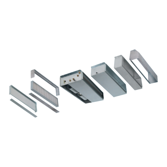
Página 5: Componenti Principali
▪ Non usare l’unità come sostegno di qualsiasi altro macchinario. ▪ Non lasciare all’interno dell’unità utensili, stracci, parti di ricambio, ecc. ▪ Non lasciare i pannelli di ispezione parzialmente chiusi: accertarsi che tutte le viti siano perfettamente serrate. ▪ Non esporre l’unità a gas infiammabili. ▪... - Página 6 DIMENSIONI HWD2 DLIO Versione orizzontale, Aspirazione aria posteriore 2-Tubi HWD2 DLIO 4-Tubi Dimensioni principali 1.200 1.200 1.200 1.600 1.600 1.600 1.280 1.280 1.280 1.680 1.680 1.680 1.160 1.160 1.160 1.560 1.560 1.560 Bocche aspirazione/ mandata 2-Tubi Peso netto 4-Tubi (1) Attacchi canale a BAIONETTA: Bocca mandata maschio; Bocca aspirazione femmina HWD2 DFIO Versione orizzontale, Aspirazione aria frontale 2-Tubi...
- Página 7 DIMENSIONI HWD2 DLIV Versione verticale, Aspirazione aria inferiore 2-Tubi HWD2 DLIV 4-Tubi Dimensioni principali 1.200 1.200 1.200 1.600 1.600 1.600 1.280 1.280 1.280 1.680 1.680 1.680 1.160 1.160 1.160 1.560 1.560 1.560 Bocche aspirazione/ mandata 2-Tubi Peso netto 4-Tubi (1) Attacchi canale a BAIONETTA: Bocca mandata maschio; Bocca aspirazione femmina HWD2 DFIV Versione verticale, Aspirazione aria frontale 2-Tubi...
- Página 8 IMbALLO Le unità vengono spedite con imballo standard costituito da uno scatolone in cartone e pallets; gli accessori vengono forniti sfusi imballati a parte o già montati sull’unità (su richiesta). All’interno dell’unità si trova una busta contenente il manuale di installazione, uso e manutenzione. Su ogni singola unità è applicata l’etichetta di identificazione riportante: •...
- Página 9 STOCCAGGIO IN CANTIERE Le unità devono essere immagazzinate al coperto al riparo da raggi solari, pioggia, vento e sabbia. INSTALLAZIONE: POSIZIONAMENTO UNITà L’INSTALLAZIONE DEVE AVVENIRE NEL RISPETTO DELLE NORME VIGENTI • Verificare la corrispondenza dell’unità e delle sue caratteristiche tecniche rispetto a quanto previsto dal progetto o da altri documenti. •...
-
Página 10: Limiti Di Funzionamento
INSTALLAZIONE: SPAZI TECNICI PER LA MANUTENZIONE 550 mm L’unità deve essere installata in posizione tale da consentire facilmente la manutenzione ordinaria e straordinaria ! • L’eventuale controsoffitto deve prevedere la possibilità di accesso alla pannellatura inferiore dell’unità per l’ispezione dei filtri e dei ven- tilatori. - Página 11 INSTALLAZIONE: SCARICO CONDENSA ▪ Si consiglia di isolare adeguatamente le tubazioni dell’acqua per evita- Scarico condensa dell’unità Scarico condensa dell’unità re gocciolamenti durante il funzionamento in raffreddamento. Ø 30 mm Ø 30 mm ▪ La rete di scarico condensa deve essere opportunamente dimensiona- ta e le tubazioni posizionate in modo da mantenere lungo il percorso una adeguata pendenza (min.
- Página 12 ASSORbIMENTO ELETTRICO: Fare riferimento ai valori di assorbimento elettrico riportati sull’etichetta matricolare dell’unità. OGNI PANNELLO COMANDI PUÓ CONTROLLARE UNA SOLA UNITÁ Per il collegamento dei controlli remoti Climaveneta con le unità, fare riferimento alla tabella sotto con l’indicazione della scheda di interfaccia (kit SPB), da utilizzare in funzione alle taglie.
-
Página 13: Prima Accensione
NOTA: Per controllare più unità (oppure una unità con 2 motori) si raccomanda di tenere le alimentazioni elettriche dei diversi motori SEPARATE ED INDIPENDENTI. Per fare questo, si raccomanda di installare 3 relays (uno per ogni velocità) con contatti indipendenti (un contatto per ogni motore da controllare) o installare la SCHEDA DI INTERFACCIA (accessorio): in questo modo qualsiasi anomalia dovesse intervenire in un motore, non va ad interferire od influenzare gli altri !! Il luogo di montaggio del pannello comandi deve essere scelto in modo che il limite di temperatura ambiente massimo e minimo venga rispettato... - Página 14 NORME PER L’UTENTE: USO AVVIAMENTO E SPEGNIMENTO DELL’UNITÁ ▪ ATTENZIONE! La prima accensione dell’unità è di competenza esclusiva di personale tecnico specializzato ed in particolare della ditta installatrice che, avendo completato i lavori dell’impianto, è in grado di verificarne la sicurezza e la funzionalità nel suo complesso. ▪...
-
Página 15: Smaltimento
NORME PER L’UTENTE: ASSISTENZA ATTENZIONE ! Per tutte le operazioni di installazione, messa in funzione, manutenzione, ecc.. avvalersi sempre dell’opera di personale professionalmente qualificato. Prima di telefonare al Servizio Tecnico accertarsi di avere a portata di mano la documentazione della macchina e possibilmente: ▪... -
Página 16: Smontaggio Gruppo Ventilante
INVERSIONE ATTACCHI IDRAULICI SMONTAGGIO GRUPPO VENTILANTE ▪ Svitare le viti, 3 sul fianco Dx e 3 sul fianco sx sul pannello inferiore ▪ La bacinella, batteria,deflettore restano solidali alla macchina. e togliere il pannello inferiore. ▪ Svitare le viti, 2 sul fianco dx e 2 sul fianco sx che tengono fissato Per il montaggio seguire il percorso contrario. -
Página 17: Ricerca Guasti
RICERCA GUASTI ATTENZIONE! Prima di accedere alla macchina, TOGLIERE TENSIONE mediante l’interruttore omnipolare posto a monte dell’unità. Per anomalie non contemplate, interpellare tempestivamente il Servizio Assistenza. GUASTO POSSIbILI CAUSE - VERIFICHE - RIMEDI ▪ Errata impostazione della velocità sul pannello comandi: Scegliere la velocità corretta sul pannello comandi ▪... -
Página 18: Avvertenze Generali
AVVERTENZE GENERALI Dopo aver tolto l’imballo assicurarsi dell’integrità e della completezza del contenuto. In caso di non rispondenza rivolgersi al Servizio Tec- nico di assistenza che ha venduto l’apparecchio. L’installazione degli apparecchi deve essere effettuata da impresa abilitata che, a fine lavoro, rilasci al proprietario la dichiarazione di conformità... - Página 19 INSTALLATION, USE AND MAINTENANCE MANUAL Ductable Hydronic Terminal Units a-HWD2 102-902 two-pipe a-HWD2 104-804 four-pipe i-HWD2 102-902 two-pipe i-HWD2 104-804 four-pipe...
-
Página 20: Safety Symbols
OBSERVATIONS In order to use the unit correctly and safely, the fitter, the user and the maintenance man, within the limits of their respective skills, must scrupulously observe the contents of this manual. • Keep this manual in a dry place, to prevent it from deteriorating, for at least 10 years for future reference. •... -
Página 21: Main Components
▪ If the unit is faulty or works incorrectly, switch it off, do not attempt to repair it and call in the fitter. ▪ When it is decided to no longer use the unit, those parts that could be sources of danger must be made harmless. The warranty becomes invalid if the instructions are not observed and if any electrical or mechanical changes are made. - Página 22 DIMENSIONS HWD2 DLIO Horizontal version, air intake from rear 2-pipe HWD2 DLIO 4-pipe Main dimensions 1.200 1.200 1.200 1.600 1.600 1.600 1.280 1.280 1.280 1.680 1.680 1.680 1.160 1.160 1.160 1.560 1.560 1.560 Intake/outlet opening 2-pipe Net weight 4-pipe (1) BAYONET duct connectors: Male outlet opening; female intake opening HWD2 DfIO Horizontal version, air intake from front 2-pipe...
- Página 23 DIMENSIONS HWD2 DLIV Vertical version, air intake from bottom 2-pipe HWD2 DLIV 4-pipe Main dimensions 1.200 1.200 1.200 1.600 1.600 1.600 1.280 1.280 1.280 1.680 1.680 1.680 1.160 1.160 1.160 1.560 1.560 1.560 Intake/outlet opening 2-pipe Net weight 4-pipe (1) BAYONET duct connectors: Male outlet opening; female intake opening HWD2 DfIV Vertical version, air intake from front 2-pipe...
- Página 24 PACKAGING The units are shipped in standard packaging comprising a large cardboard box and pallets; the accessories ares sup- plied loose packed separately or mounted on the unit (on request). An envelope containing the installation, use and maintenance manual is placed inside the unit. An identity label is placed on each unit indicating: •...
- Página 25 STORAGE ON THE WORKSITE INSTALLATION: POSITIONING THE UNIT INSTALLATION: POSITIONING THE UNIT INSTALLATION MUST BE PERfORMED IN OBSERVANCE Of CURRENT REGULATIONS • Make sure the unit and its technical specifications match the design or other documents. • Do not leave any packaging within the reach of children as it is a source of danger. •...
-
Página 26: Operating Range
INSTALLATION: CLEARANCE fOR MAINTENANCE 550 mm The unit must be installed in a position that allows routine and unscheduled maintenance to be carried out easily! • Any false-ceilings must allow the possibility to access the bottom panelling of the unit so as to inspect the filters and the fans. •... - Página 27 INSTALLATION: CONDENSATE DRAIN ▪ The water piping should be suitably insulated so as to avoid dripping Unit condensate drain Unit condensate drain during operation in cooling mode. Ø 30 mm Ø 30 mm ▪ The condensate drain line must be suitably sized and the piping laid so that there is a suitable incline (min.
- Página 28 POWER CONSUMPTION: See the power consumption values shown on the unit’s rating plate. EACH CONTROL PANEL CAN ONLy MANAGE ONE UNIT To connect Climaveneta remote controls to the unit, see the table below, listing the interface board (SPB kit) to be used, according to unit size. SIZES...
- Página 29 NOTE: To control multiple units (or one unit with two motors), the power supply to the different motors should be SEPARATE AND INDE- PENDENT. To do this, it is recommended to install three relays (one for each speed) with independent contacts (one contact for each motor being controlled) or install the INTERfACE BOARD (accessory): in this way, any faults will only affect one motor, and should not interfere with or affect the others !! The place where the control panel is mounted must be chosen so that the maximum and minimum room temperature limits are not exceeded (0-45°C;...
- Página 30 USER REQUIREMENTS: USE STARTING AND STOPPING THE UNIT ▪ WARNING! The unit must only be started for the first time by specialist technical personnel, or specifically by the installer who, having completed the work on the system, can verify its safety and overall operation. ▪...
- Página 31 USER INSTRUCTIONS: ASSISTANCE ATTENTION ! Always ensure that all installation, start-up and maintenance operations, etc. are performed by professionally qualified people. Before calling the Technical Assistance Service, make sure you have the following machine documentation to hand: ▪ Model of unit and Serial number ▪...
- Página 32 REVERSING THE HyDRAULIC CONNECTIONS DISMANTLING THE fAN UNIT ▪ Unscrew the screws on the bottom panel, 3 on the right and 3 on the ▪ The pan, coil and louver will remain attached to the unit. left, and remove the panel. ▪...
- Página 33 RICERCA GUASTI ATTENTION ! Before accessing the unit, DISCONNECT IT fROM THE MAINS POWER SUPPLy using the upline multi-pole switch. In case any unexpected problems arise, promptly call in the Technical Assistance Service. fAULT POSSIBLE REASONS - CONTROL - REMEDIES ▪...
-
Página 34: General Information
GENERAL INfORMATION After removing the packaging, make sure the contents are undamaged and complete. If this is not the case, contact the Technical Assist- ance Service the unit was purchased from. The equipment must be installed by an authorised company which must also give the owner a declaration of conformity of installation performed according to the rules of good workmanship, that is, in compliance with current regulations and the instructions given by the company in this booklet. - Página 35 MANUEL D’INSTALLATION - UTILISATION - ENTRETIEN Unités terminales à eau gainables a-HWD2 102-902 à deux tubes a-HWD2 104-804 à quatre tubes i-HWD2 102-902 à deux tubes i-HWD2 104-804 à quatre tubes...
-
Página 36: Symboles De Sécurité
OBSERVATIONS Pour une utilisation correcte et sûre de l’unité, l’utilisateur et personnel d’entretien, pour leurs domaines respectifs de compétence, sont tenus de respecter scrupuleusement les indications de ce manuel. • Conserver ce manuel dans un endroit sec pour éviter qu’il ne se détériore, pendant au moins 10 ans en vue de toute consultation future. •... -
Página 37: Composants Principaux
▪ Ne pas utiliser l'unité comme support pour quelque machine que ce soit. ▪ Ne pas laisser à l'intérieur de l'unité des outils, chiffons, pièces de rechange, etc. ▪ Ne pas laisser les panneaux d'inspection partiellement fermés : s'assurer que toutes les vis sont bien serrées. ▪... - Página 38 DIMENSIONS HWD2 DLIO Version horizontale, aspiration air à l’arrière 2 tubes HWD2 DLIO 4 tubes Dimensions principales 1.200 1.200 1.200 1.600 1.600 1.600 1.280 1.280 1.280 1.680 1.680 1.680 1.160 1.160 1.160 1.560 1.560 1.560 Bouches aspiration/ soufflage 2 tubes Poids net 4 tubes (1) Raccords gaine à...
- Página 39 DIMENSIONS HWD2 DLIV Version verticale, Aspiration air en bas 2 tubes HWD2 DLIV 4 tubes Dimensions principales 1.200 1.200 1.200 1.600 1.600 1.600 1.280 1.280 1.280 1.680 1.680 1.680 1.160 1.160 1.160 1.560 1.560 1.560 Bouches aspiration/ soufflage 2 tubes Poids net 4 tubes (1) Raccords gaine à...
- Página 40 EMBALLAGE Les unités sont expédiées avec un emballage standard constitué d’une grosse boîte en carton et de palettes ; les acces- soires sont livrés en vrac ou emballées séparément ou déjà montés sur l’unité (sur demande). Le manuel d’installation, utilisation et entretien est dans un sachet à l’intérieur de l’unité. Chaque unité est muni d’une étiquette d’identification indiquant : •...
- Página 41 STOCKAGE SUR SITE Les unités doivent être entreposées à l’intérieur et à l’abri du soleil, de la pluie, du vent et du sable. INSTALLATION : POSITIONNEMENT DE L’UNITé L’INSTALLATION DOIT ÊTRE CONFORME AUX NORMES EN VIGUEUR • Vérifier la correspondance de l’unité et de ses caractéristiques techniques par rapport à ce qui est prévu par le projet ou d’autres documents. •...
-
Página 42: Limites De Fonctionnement
INSTALLATION: DéGAGEMENTS POUR L’ENTRETIEN 550 mm L’unité doit être installée de façon à permettre aisément l’entretien courant et exceptionnel! • L’éventuel faux-plafond doit permettre d’accéder au panneau infé- rieur de l’unité pour l’inspection des filtres et des ventilateurs. • Du côté des raccords hydrauliques prévoir un espace d’au moins 400 400 mm mm pour le montage des tuyaux et des vannes. - Página 43 INSTALLATION: éCOULEMENT DES CONDENSATS ▪ Il est conseillé d’isoler les tuyauteries de l’eau afin d’éviter la formation Évacuation des condensats Évacuation des condensats de gouttes pendant le fonctionnement en refroidissement. de l'unité Ø 30 mm de l'unité Ø 30 mm ▪...
- Página 44 PUISSANCE ABSORBéE: Se reporter aux valeurs de puissance absorbée indiquées sur l’étiquette de l’unité. CHAqUE PANNEAU DE COMMANDES NE PEUT COMMANDER qU’UNE SEULE UNITé Pour le raccordement des commandes déportées Climaveneta aux unités, se reporter au tableau ci-dessous avec l’indication de la carte d’interface (kit SPB) à utiliser en fonction des tailles.
-
Página 45: Première Mise En Marche
NOTE: Pour commander plusieurs unités (ou une unité avec 2 moteurs) les alimentations électriques des différents moteurs doivent être SéPARéES ET INDéPENDANTES. Pour cela il est recommandé d’installer 3 relais (un par vitesse) avec des contacts indépendants (un contact par moteur à commander) ou d’installer la CARTE D’INTERFACE (accessoire): de cette façon toute anomalie se produisant dans un moteur n’aura aucune répercussion sur les autres! L’emplacement de montage du panneau de commandes doit être choisi de façon à... - Página 46 NORMES POUR L’UTILISATEUR: UTILISATION MISE EN MARCHE ET ARRÊT DE L’UNITé ▪ ATTENTION! La première mise en marche de l’unité doit être effectuée exclusivement par un professionnel spécialisé et en particulier par un technicien de l’installateur qui, après avoir terminé les travaux d’installation, est en mesure d’en vérifier la sécurité et le fonction- nement dans son ensemble.
- Página 47 NORMES POUR L’UTILISATEUR : ASSISTANCE ATTENTION ! Pour les opérations d’installation, mise en service, entretien, etc. veuillez toujours faire appel à un personnel professionnel qualifié. Avant d’appeler le Service Technique, assurez-vous d’avoir sous la main la documentation de la machine et, si possible : ▪...
-
Página 48: Démontage Groupe De Ventilation
INVERSION DES RACCORDS HyDRAULIqUES DéMONTAGE GROUPE DE VENTILATION ▪ Dévisser les vis, 3 sur le flanc Dt et 3 sur le flanc gche, sur le pan- ▪ Le bac, la batterie et le déflecteur restent solidaires de la machine. neau inférieur et retirer le panneau inférieur. ▪... -
Página 49: Recherche Des Pannes
RECHERCHE DES PANNES ATTENTION ! Avant d’entrer dans la machine, METTRE HORS TENSION en appuyant sur le disjoncteur multipolaire installé en amont de l’unité. Pour les anomalies non prévues, contacter immédiatement le Service d’Assistance. PANNE CAUSES POSSIBLES - CONTRÔLES - SOLUTIONS ▪... -
Página 50: Avertissements Généraux
AVERTISSEMENTS GéNéRAUX Après avoir enlevé l'emballage, vérifier l'intégrité et l'intégralité du contenu. En cas de problème, veuillez contacter le Service Technique qui a vendu l'appareil. L'installation des appareils doit être effectuée par une société habilitée qui, à la fin du travail, délivrera au propriétaire la déclaration de conformité... - Página 51 HANDBUCH FÜR INSTALLATION - GEBRAUCH - WARTUNG Hydronik-Endgeräte mit Kanalanschluss a-HWD2 102-902 mit zwei Rohren a-HWD2 104-804 mit vier Rohren i-HWD2 102-902 mit zwei Rohren i-HWD2 104-804 mit vier Rohren...
-
Página 52: Sicherheitsvorschriften
HINWEISE Für den korrekten und sicheren Gebrauch des Geräts müssen der Installateur, der Benutzer und der Wartungsfachmann im Rahmen ihrer Kompe- tenzen die Angaben dieses Handbuchs streng einhalten. • Dieses Handbuch an einem trockenen Ort (um es nicht zu beschädigen) mindestens 10 Jahre lang für den künftigen Gebrauch aufbewahren. •... - Página 53 ▪ Das Gerät nicht als Abstützung für andere Geräte verwenden. ▪ Im Gerät keine Werkzeuge, Lappen, Ersatzteile u.ä. zurücklassen. ▪ Die Inspektionsplatten nicht halb geschlossen lassen: sicherstellen, dass alle Schrauben gut festgezogen sind. ▪ Das Gerät keinen entflammbaren Gasen aussetzen. ▪...
- Página 54 ABMESSUNGEN HWD2 DLIO Horizontale Version, Luftansaug hinten 2 Rohre HWD2 DLIO 4 Rohre Hauptabmessungen 1.200 1.200 1.200 1.600 1.600 1.600 1.280 1.280 1.280 1.680 1.680 1.680 1.160 1.160 1.160 1.560 1.560 1.560 Ansaug-/Ausblasöffnungen 2 Rohre Nettogewicht 4 Rohre (1) Kanal mit BAJONETTVERSCHLUSS: Ausblasöffnung Stecker; Ansaugöffnung Buchse HWD2 DFIO Horizontale Version, Luftansaug vorne 2 Rohre...
- Página 55 ABMESSUNGEN HWD2 DLIV Vertikale Version, Luftansaug unten 2 Rohre HWD2 DLIV 4 Rohre Hauptabmessungen 1.200 1.200 1.200 1.600 1.600 1.600 1.280 1.280 1.280 1.680 1.680 1.680 1.160 1.160 1.160 1.560 1.560 1.560 Ansaug-/Ausblasöffnungen 2 Rohre Nettogewicht 4 Rohre (1) Kanal mit BAJONETTVERSCHLUSS: Ausblasöffnung Stecker; Ansaugöffnung Buchse HWD2 DFIV Vertikale Version, Luftansaug vorne 2 Rohre...
- Página 56 VERPACKUNG Die Geräte werden mit Standardverpackung, bestehend aus Karton und Palette, geliefert; das Zubehör wird lose und getrennt verpackt oder bereits am Gerät montiert (auf Wunsch) geliefert. Im Gerät befindet sich eine Hülle mit dem Handbuch für Installation, Gebrauch und Wartung. An jedem einzelnen Gerät befin- det sich ein Typenschild mit folgenden Angaben: •...
-
Página 57: Lagerung Auf Der Baustelle
LAGERUNG AUF DER BAUSTELLE Die Geräte müssen in einem überdachten und vor Sonnenstrahlen, Regen, Wind und Sand geschützten Raum gelagert werden. INSTALLATION: ANORDNUNG DES GERäTS DIE INSTALLATION MUSS UNTER EINHALTUNG DER GÜLTIGEN VORSCHRIFTEN AUSGEFÜHRT WERDEN • Prüfen, ob das Gerät und seine technischen Eigenschaften mit den Vorgaben des Projekts oder anderer Dokumente übereinstimmen. •... - Página 58 INSTALLATION: TECHNISCHE FREIRäUME FÜR DIE WARTUNG 550 mm Das Gerät muss bei der Installation so platziert werden, dass die planmäßige und außerplanmäßige Wartung problemlos möglich ist! • Bei einer abgehängten Decke muss der Zugang zur unteren Ver- kleidung des Gerätes möglich sein, um Filter und Ventilatoren zu inspektionieren.
- Página 59 MAX 15 BAR INSTALLATION: KONDENSWASSERAUSLASS ▪ Es wird empfohlen, die Wasserrohrleitungen gut zu isolieren, um wäh- Kondensatablauf des rend des Kühlbetriebs Tropfenbildung zu vermeiden. Gerätes Ø 30 mm ▪ Das Kondensatablaufnetz muss richtig bemessen sein und die Lei- Kondensatablauf des tungen müssen so verlegt werden, dass ihr Verlauf ein ausreichendes Gerätes Ø...
- Página 60 STROMAUFNAHME: Auf die Stromaufnahmewerte Bezug nehmen, die auf dem Leistungsschild des Gerätes angegeben sind. JEDES BEDIENFELD KANN NUR EIN GERäT STEUERN Für den Anschluss der Fernsteuerungen Climaveneta an die Geräte wird auf die nachfolgende Tabelle verwiesen, mit Angabe der Schnittstellenkarte (Kit SPB), die je nach Baugröße zu verwenden ist.
-
Página 61: Erstes Einschalten
HINWEIS: Um mehrere Geräte zu steuern (oder ein Gerät mit 2 Motoren) muss die Stromversorgung der einzelnen Motoren SEPARAT UND UNABHäNGIG VONEINANDER erfolgen. Dazu müssen 3 Relais (eines für jede Drehzahl) mit unabhängigen Kontakten (ein Kontakt für je- den zu steuernden Motor) oder die SCHNITTSTELLENKARTE (Zubehör) installiert werden: auf diese Weise hat eine Störung, die bei einem Motor auftritt, keinerlei Einfluss auf die anderen Motoren !! Der Ort für die Montage des Bedienfelds muss so gewählt werden, dass die Höchst- und Mindestgrenze der Raumtemperatur eingehalten werden 0÷45°C ;... - Página 62 NORMEN FÜR DEN BENUTZER: GEBRAUCH EIN- UND AUSSCHALTEN DES GERäTES ▪ ACHTUNG! Die erste Inbetriebnahme des Gerätes unterliegt der ausschließlichen Zuständigkeit von technischem Fachpersonal und insbesondere der Installationsfirma, die, da sie die Arbeiten an der Anlage zu Ende geführt hat, in der Lage ist, ihre Sicherheit und Funk- tionstüchtigkeit insgesamt zu überprüfen.
- Página 63 VORSCHRIFTEN FÜR DEN BENUTZER: KUNDENDIENST ACHTUNG ! Für alle Installations-, Inbetriebnahme- und Wartungsarbeiten usw. muss immer qualifiziertes Fachpersonal herangezogen werden. Bevor Sie den Kundendienst anrufen, legen Sie sich die Maschinendokumentation bereit, und zwar: ▪ Gerätemodell und Herstellnummer ▪ Beschreibung, auch nur generell, der Art der Installation VORSCHRIFTEN FÜR DEN BENUTZER: ERSATZTEILE Zur Erhaltung von Sicherheit und Qualität wird empfohlen, immer Original-Komponenten und -Ersatzteile zu verwenden.
- Página 64 FEHLERSUCHE AUSBAU DER LÜFTEREINHEIT ▪ Die Schrauben losschrauben, 3 an der rechten Seite und 3 an der linken ▪ Kondensatschale, Register und Leitblech bleiben fest mit dem Gerät Seite an der unteren Verkleidung, und die untere Verkleidung entfernen. verbunden. ▪ Die Schrauben losschrauben, 2 an der rechten Seite und 2 an der linken Seite, mit denen die Lüftereinheit befestigt ist.
- Página 65 FEHLERSUCHE ACHTUNG! Vor dem Arbeiten am Gerät die SPANNUNG mit dem Allpolschalter vor dem Gerät ABSCHALTEN. Bei Auftreten hier nicht angegebener Störungen rechtzeitig den Kundendienst verständigen. FEHLER MÖGLICHE URSACHEN - KONTROLLEN - ABHILFE ▪ Falsche Geschwindigkeitseinstellung am Bediengerät: richtige Geschwindigkeit am Bediengerät einstellen ▪...
-
Página 66: Allgemeine Hinweise
ALLGEMEINE HINWEISE Nach dem Auspacken prüfen, ob der Inhalt unversehrt und vollständig ist. Bei Mängeln den technischen Kundendienst verständigen, der Ihnen das Gerät verkauft hat. Die Installation der Geräte muss von einer befugten Fachfirma vorgenommen werden, die dem Besitzer bei Arbeitsende eine Konformi- tätserklärung für die fachgerecht ausgeführte Installation ausstellt, d.h. - Página 67 MANUAL DE INSTALACIÓN - USO - MANTENIMIENTO Unidades terminales hidrónicas canalizables a-HWD2 102-902 con dos tubos a-HWD2 104-804 con cuatro tubos i-HWD2 102-902 con dos tubos i-HWD2 104-804 con cuatro tubos...
-
Página 68: Observaciones
OBSERVACIONES A fin de utilizar la unidad de modo correcto y seguro, el instalador, el usuario y el encargado del mantenimiento, según les corresponda, tienen que respetar atentamente lo que se indica en este manual. • Guardar este manual en un lugar seco, para evitar su deterioro, durante por lo menos 10 años para eventuales referencias futuras. •... -
Página 69: Componentes Principales
▪ No utilizar la unidad como un soporte para cualquier otra máquina. ▪ No dejar herramientas, trapos, piezas de repuesto, etc. en el interior de la unidad. ▪ No dejar los paneles de inspección parcialmente cerrados: asegurarse de que todos los tornillos estén apretados perfectamente. ▪... - Página 70 MEDIDAS HWD2 DLIO Versión horizontal, aspiración de aire posterior 2-Tubos HWD2 DLIO 4-Tubos Medidas principales 1.200 1.200 1.200 1.600 1.600 1.600 1.280 1.280 1.280 1.680 1.680 1.680 1.160 1.160 1.160 1.560 1.560 1.560 Bocas de aspiración/ descarga 2-Tubos Peso neto 4-Tubos (1) Conexiones del canal en BAYONETA: Boca de descarga macho;...
- Página 71 MEDIDAS HWD2 DLIV Versión vertical, Aspiración del aire inferior 2-Tubos HWD2 DLIV 4-Tubos Medidas principales 1.200 1.200 1.200 1.600 1.600 1.600 1.280 1.280 1.280 1.680 1.680 1.680 1.160 1.160 1.160 1.560 1.560 1.560 Bocas de aspiración/ descarga 2-Tubos Peso neto 4-Tubos (1) Conexiones del canal en BAYONETA: Boca de descarga macho;...
- Página 72 EMBALAjE Las unidades se envían con un embalaje estándar constituido por una caja grande de cartón y palets; los accesorios se suministran a granel, embalados por separado, o ya instalados en la unidad (bajo pedido). En el interior de la unidad hay un sobre que contiene el manual de instalación, uso y mantenimiento. En cada unidad está aplicada la etiqueta de identificación con la indicación de: •...
-
Página 73: Almacenamiento En La Obra
ALMACENAMIENTO EN LA OBRA Las unidades se deben almacenar en un ambiente cubierto y protegidas contra los rayos solares, la lluvia, el viento y la arena. INSTALACIÓN: COLOCACIÓN DE LAS UNIDADES LA INSTALACIÓN SE DEBE REALIZAR RESPETANDO LAS NORMAS VIGENTES •... - Página 74 INSTALACIÓN: ESPACIOS TÉCNICOS PARA EL MANTENIMIENTO 550 mm La unidad debe instalarse en una posición tal que permita realizar fácilmente el mantenimiento ordinario y extraordinario. • El eventual falso techo debe prever la posibilidad de acceder al re- vestimiento de paneles inferior de la unidad para la inspección de los filtros y los ventiladores.
-
Página 75: Instalación: Descarga Del Condensado
INSTALACIÓN: DESCARGA DEL CONDENSADO ▪ Se recomienda aislar adecuadamente las tuberías del agua para evitar Desagüe del agua de Desagüe del agua de que goteen durante el funcionamiento en refrigeración. condensación de condensación de la unidad Ø 30 mm la unidad Ø 30 mm ▪... -
Página 76: Instalación: Conexión Eléctrica
CADA PANEL DE MANDOS PUEDE CONTROLAR UNA ÚNICA UNIDAD Para la conexión de los controles a distancia Climaveneta con las unidades, hacer referencia a la tabla siguiente con la indicación de la tarjeta de interfaz (kit SPB) a utilizar en función de los tamaños. -
Página 77: Instalación: Conexiones Aeráulicas
NOTA: Para controlar más unidades (o bien una unidad con 2 motores) se aconseja tener los suministros eléctricos de los distintos moto- res SEPARADOS E INDEPENDIENTES. Para ello se aconseja instalar 3 relés (uno para cada velocidad) con contactos independientes (un contacto para cada motor que deba controlarse) o instalar la TARjETA DE INTERFAZ (accesorio): así... -
Página 78: Normas Para El Usuario: Uso
NORMAS PARA EL USUARIO: USO PUESTA EN MARCHA Y APAGADO DE LA UNIDAD ▪ ¡ATENCIÓN! El primer encendido de la unidad deberá realizarlo únicamente personal técnico especializado y en concreto de la empresa instaladora que, una vez finalizados los trabajos de instalación, está capacitado para verificar la seguridad y la funcionalidad del con- junto de la instalación. - Página 79 NORMAS PARA EL USUARIO: ASISTENCIA ¡ATENCIÓN! Para todas las operaciones de instalación, puesta en funcionamiento, mantenimiento, etc. dirigirse siempre a personal calificado profesionalmente. Antes de llamar el Servicio Técnico, asegurarse de tener a disposición la documentación de la máquina y, de ser posible: ▪...
-
Página 80: Desmontaje Del Grupo Ventilador
INVERSIÓN EMPALMES HIDRáULICOS DESMONTAjE DEL GRUPO VENTILADOR ▪ Desatornillar los tornillos, 3 en el lado derecho y 3 en el izquierdo en ▪ La bandeja, la batería y el deflector quedan sujetos a la máquina. el panel inferior y retirar dicho panel. ▪... -
Página 81: Identificación De Las Averías
IDENTIFICACIÓN DE LAS AVERíAS ¡ATENCIÓN! Antes de acceder a la máquina, CORTAR LA TENSIÓN mediante el interruptor omnipolar situado antes de la unidad. En lo que se refiere a las anomalías no previstas, dirigirse prontamente al Servicio de Asistencia. AVERíA POSIBLES AVERíAS - CONTROLES - REMEDIOS ▪... -
Página 82: Advertencias Generales
ADVERTENCIAS GENERALES Tras haber quitado el embalaje, asegurarse de que el contenido se encuentre intacto y completo. En caso contrario, dirigirse al Servicio Técnico de asistencia que ha vendido el aparato. La instalación de los aparatos la debe efectuar una empresa habilitada que, al final del trabajo, entregará al propietario la declaración de conformidad de instalación realizada según las reglas del arte, es decir con arreglo a las Normas vigentes y las indicaciones que la empresa ha facilitado en este manual. - Página 83 MANUAL DE INSTALAÇÃO - USO - MANUTENÇÃO Unidades terminais hidrónicas canalizáveis a-HWD2 102-902 de dois tubos a-HWD2 104-804 de quatro tubos i-HWD2 102-902 de dois tubos i-HWD2 104-804 de quatro tubos...
-
Página 84: Símbolos De Segurança
OBSERVAÇÕES A fim de garantir uma utilização correta e segura da unidade, o instalador, o utilizador e o técnico de manutenção, dentro das respetivas competên- cias, devem respeitar escrupulosamente quanto indicado neste manual. • Guardar este manual num local enxuto, para evitar a deterioração, por pelo menos 10 anos, para eventual referência futura. •... - Página 85 ▪ Não utilizar a unidade como suporte de qualquer outra máquina. ▪ Não deixar ferramentas, farrapos, peças de reposição, etc. dentro da unidade. ▪ Não deixar os painéis de inspeção parcialmente fechados: verificar que todos os parafusos estejam perfeitamente apertados. ▪...
- Página 86 DIMENSÕES HWD2 DLIO Versão horizontal, Aspiração de ar traseira 2 Tubos HWD2 DLIO 4 Tubos Dimensões principais 1.200 1.200 1.200 1.600 1.600 1.600 1.280 1.280 1.280 1.680 1.680 1.680 1.160 1.160 1.160 1.560 1.560 1.560 Bocas de aspiração/ saída 2 Tubos Peso líquido 4 Tubos (1) Uniões de canal de BAIONETA: Boca de saída macho;...
- Página 87 DIMENSÕES HWD2 DLIV Versão horizontal, Aspiração de ar inferior 2 Tubos HWD2 DLIV 4 Tubos Dimensões principais 1.200 1.200 1.200 1.600 1.600 1.600 1.280 1.280 1.280 1.680 1.680 1.680 1.160 1.160 1.160 1.560 1.560 1.560 Bocas de aspiração/ saída 2 Tubos Peso líquido 4 Tubos (1) Uniões de canal de BAIONETA: Boca de saída macho;...
- Página 88 EMBALAGEM As unidades são fornecidas com embalagem standard constituída por uma caixa de papelão e pallets; os acessórios são fornecidos a granel, embalados separadamente ou já montados na unidade (sob pedido) No interior da unidade encontra-se um envelope que contém o manual de instalação, uso e manutenção. Em cada unidade está...
- Página 89 ARMAZENAMENTO NA OBRA As unidades devem ser armazenadas num local coberto ao abrigo da luz direta do sol, da chuva, do vento e da areia. INSTALAÇÃO: POSICIONAMENTO DA UNIDADE A INSTALAÇÃO DEVE SER EFETUADA DE ACORDO COM AS NORMAS VIGENTES •...
-
Página 90: Limites De Funcionamento
INSTALAÇÃO: ESPAÇOS TÉCNICOS PARA A MANUTENÇÃO 550 mm A unidade deve ser instalada numa posição que permita facilmen- te a manutenção de rotina e extraordinária! • O eventual tecto falso deve prever a possibilidade de acesso aos painéis inferiores da unidade para a inspecção dos filtros e dos ven- tiladores. - Página 91 INSTALAÇÃO: DESCARGA DO CONDENSADO ▪ Recomendamos que isole devidamente as tubagens da água para evi- Descarga da condensação Descarga da condensação tar gotejamentos durante o funcionamento no modo de arrefecimento. da unidade Ø 30 mm da unidade Ø 30 mm ▪...
- Página 92 CONSUMO ELÉCTRICO: Consulte os valores de consumo eléctrico indicados na etiqueta do número de série da unidade. CADA PAINEL DE COMANDOS PODE CONTROLAR UMA ÚNICA UNIDADE Para a ligação dos controlos remotos Climaveneta com as unidades, consulte a tabela abaixo com a indicação da placa de interface (kit SPB), a utilizar em função dos tamanhos.
-
Página 93: Primeira Ligação
NOTA: Para controlar várias unidades (ou uma unidade com 2 motores) recomendamos que mantenha as alimentações eléctricas dos diversos motores SEPARADAS E INDEPENDENTES. Para tal, recomendamos que instale 3 relés (um por cada velocidade) com contactos independentes (um contacto por cada motor a controlar) ou que instale a PLACA DE INTERFACE (acessório): deste modo, qualquer ano- malia que ocorra num motor, não interferirá... - Página 94 NORMAS PARA O UTILIZADOR: UTILIZAÇÃO LIGAR E DESLIGAR A UNIDADE ▪ ATENÇÃO! A primeira ligação da unidade é da competência exclusiva de pessoal técnico especializado e em particular da empresa instaladora que, uma vez concluídos os trabalhos do sistema, está em condições de verificar a sua segurança e funcionalidade nas respectivas instalações.
- Página 95 NORMAS PARA O UTILIZADOR: ASSISTÊNCIA ATENÇÃO ! Para todas as operações de instalação, colocação em funcionamento, etc. servir-se sempre de pessoal qualificado profissionalmente. Antes de telefonar para o Serviço Técnico, acertar-se de ter ao alcance da mão a documentação da máquina e, possivelmente: ▪...
- Página 96 INVERSÃO DAS CONEXÕES HIDRáULICAS DESMONTAGEM DO GRUPO DE VENTILAÇÃO ▪ Desaperte os parafusos, 3 no lado Dir. e 3 no lado Esq., no painel ▪ O depósito, bateria, deflector ficam fixos à máquina. inferior e retire o painel inferior. ▪ Desaperte os parafusos, 2 no lado Dir. e 2 no lado Esq., que man- Para a montagem, siga o percurso contrário.
-
Página 97: Busca De Falhas
BUSCA DE FALHAS ATENÇÃO! Antes de aceder à máquina, CORTAR A TENSÃO mediante o interruptor omnipolar situado antes da unidade. Para anomalias não previstas, contactar imediatamente o Serviço de Assistência. FALHA CAUSAS PROVáVEIS - CONTROLOS - SOLUÇÕES ▪ Definição errada da velocidade no painel de comandos: escolher a velocidade correta no painel de comandos ▪... -
Página 98: Advertências Gerais
ADVERTÊNCIAS GERAIS Depois de ter retirado a embalagem, controlar que o conteúdo esteja intacto e completo. No caso contrário, contacte o Serviço Técnico de assistência que vendeu o aparelho. A instalação dos aparelhos deve ser efetuada por uma empresa habilitada que, no final do trabalho, entregue ao proprietário a declara- ção de conformidade da instalação feita segundo as regras da boa arte, isto é, no cumprimento das normas em vigor e das instruções fornecidas pela empresa com este manual. - Página 99 ИНСТРУКЦИЯ ПО УСТАНОВКЕ, ИСПОЛЬЗОВАНИЮ И ОБСЛУЖИВАНИЮ Жидкостной канальный терминал a-HWD2 102-902 двухтрубный a-HWD2 104-902 четырехтрубный i-HWD2 102-902 двухтрубный i-HWD2 104-902 четырехтрубный...
-
Página 100: Предупреждающие Знаки
ЗАМЕЧАНИЯ Для того, что бы эксплуатация прибора была безопасной и правильной, пользователь и ремонтник, в соответствии со своей компетенцией, обязаны тщательно выполнять все то, что указано в данной инструкции. • Храните данную инструкцию в сухом месте, чтобы избежать ее повреждения и последующего использования в течение не менее 10 лет. •... -
Página 101: Основные Компоненты
▪ Не используйте прибор, как подставку для другого оборудования. ▪ Не оставляйте в приборе инструменты, тряпки, запчасти и т.д. ▪ Не оставляйте инспекционные панели в частично приоткрытом виде, убедитесь, что все винты хорошо затянуты. ▪ Не помещайте устройство в среду с горючим газом. ▪... - Página 102 РАЗМЕРЫ HWD2 DLIO Горизонтальная модель, задний забор воздуха 2 трубы HWD2 DLIO 4 трубы мм мм Основные размеры мм 1.200 1.200 1.200 1.600 1.600 1.600 мм 1.280 1.280 1.280 1.680 1.680 1.680 мм 1.160 1.160 1.160 1.560 1.560 1.560 Отверстия всасывания/ подачи...
- Página 103 РАЗМЕРЫ HWD2 DLIV Вертикальная модель, нижний забор воздуха 2 трубы HWD2 DLIV 4 трубы мм мм Основные размеры мм 1.200 1.200 1.200 1.600 1.600 1.600 мм 1.280 1.280 1.280 1.680 1.680 1.680 мм 1.160 1.160 1.160 1.560 1.560 1.560 Отверстия всасывания/ подачи...
- Página 104 УПАКОВКА Приборы отгружаются в стандартной упаковке, состоящей из картонной коробки и поддонов. Аксессуары постав- ляются россыпью в отдельной упаковке или уже установлены на приборе (по запросу). Внутри прибора находится конверт, содержащий инструкцию по монтажу, эксплуатации и обслуживанию. На каждый прибор установлена идентификационная этикетка с данными: •...
- Página 105 ХРАНЕНИЕ НА ПЛОЩАДКЕ Приборы должны храниться в месте, закрытом от солнечных лучей, дождя, ветра и песка. УСТАНОВКА: ПОЗИЦИОНИРОВАНИЕ ПРИБОРА МОНТАЖ ДОЛЖЕН ПРОИЗВОДИТЬСЯ С СОБЛЮДЕНИЕМ ДЕЙСТВУЮЩИХ НОРМ • Убедитесь в соответствии прибора и его технических характеристик по сравнению с тем, что предусмотрено в проекте или другой докумен- тации.
- Página 106 УСТАНОВКА: ТЕХНИЧЕСКИЕ ЗАЗОРЫ ДЛЯ ОБСЛУЖИВАНИЯ МИН. 550 mm Прибор должен быть установлен в положение, которое по- зволяет с легкостью производить плановое и внеплановое обслуживание! • Фальшпотолок, если он есть, должен предусматривать возмож- ность доступа к нижней панели прибора для проверки фильтров и...
- Página 107 УСТАНОВКА: СЛИВ КОНДЕНСАТА ▪ Рекомендуется тщательно изолировать трубы с водой, чтобы из- С С а а а а а а бежать появление капель влаги во время охлаждения. Ø 30 Ø 30 ▪ Сеть сброса конденсата должна надлежащим образом быть рас- считана, а...
-
Página 108: Подключение Электроэнергии
ПОТРЕБЛЕНИЕ ЭЛЕКТРОЭНЕРГИИ: См. значения потребляемой мощности, указанные на этикетке прибора. КАЖДАЯ ПАНЕЛЬ УПРАВЛЕНИЯ МОЖЕТ УПРАВЛЯТЬ ТОЛЬКО ОДНИМ БЛОКОМ Для подключения пульта дистанционного управления Climaveneta к приборам обратитесь к таблице, приведенной ниже с указанием платы интерфейса (комплект SPB), которая используется в зависимости от модели. -
Página 109: Информация Для Пользователя
ПРИМЕЧАНИЕ: Для управления несколькими устройствами (или прибором с 2 двигателями) рекомендуется поддерживать НЕЗА- ВИСИМОЕ И ОТДЕЛЬНОЕ питание двигателей. Для этой цели рекомендуется установить 3 реле (по одному на скорость) с неза- висимыми контактами (один контакт для каждого управляемого двигателя) или установить ИНТЕРФЕЙСНУЮ ПЛАТУ (аксессуар), чтобы... - Página 110 РУКОВОДСТВО ПОЛЬЗОВАТЕЛЯ: ЭКСПЛУАТАЦИЯ ЗАПУСК И ВЫКЛЮЧЕНИЕ ПРИБОРА ▪ ВНИМАНИЕ! Первое включение прибора является исключительной компетенцией квалифицированного технического персона- ла, и в частности компании, которая занимается монтажом, которая, завершив работу, имеет возможность проверки безопасно- сти и общего функционирования. ▪ Перед первым включением прибора, убедитесь, что компания-установщик произвела все требуемые от нее работы. ▪...
- Página 111 РУКОВОДСТВО ПОЛЬЗОВАТЕЛЯ: ОБСЛУЖИВАНИЕ ВНИМАНИЕ! При выполнении всех операций по монтажу, вводу в эксплуатацию, техническому обслуживанию и т.д. проконсультируйтесь у квалифицированного специалиста. Прежде чем позвонить в сервисную технической службу убедитесь, что под рукой у вас есть документация машины и, по возможности: ▪...
- Página 112 ПЕРЕНОС ПРИ ПОДВОДЕ ВОДЫ СНЯТИЕ БЛОКА ВЕНТИЛЯТОРА ▪ Отвинтите винты: 3 на правой и 3 на левой стороне нижней па- ▪ Поддон, батарея, дефлектор остаются закрепленными на при- нели, и снимите нижнюю панель. боре. ▪ Отвинтите винты: 2 на правой и 2 на левой стороне крепления вентилятора.
-
Página 113: Поиск Неисправностей
ПОИСК НЕИСПРАВНОСТЕЙ ВНИМАНИЕ! До того, как начать работать внутри прибора ОТКЛЮЧИТЕ НАПРЯЖЕНИЕ при помощи многополярного выключателя, расположенного до прибора. При неисправностях, не упомянутых в данной инструкции, своевременно свяжитесь с местной сервисной службой. НЕИСПРАВНОСТЬ ВОЗМОЖНЫЕ ПРИЧИНЫ - ПРОВЕРКИ - ИСПРАВЛЕНИЕ ▪ Неправильная регулировка скорости на панели управления: Задайте правильную скорость на панели управления. -
Página 114: Общие Предупреждения
ОБЩИЕ ПРЕДУПРЕЖДЕНИЯ После снятия упаковки, убедитесь в целостности и комплектности содержимого. В случае несоответствия обратитесь службу технического сервиса, компании которая продала прибор. Установка приборов должна осуществляться квалифицированным предприятием, которое в конце работы вместе с владельцем подписывает акт, что произведенная установка выполнена качественно, т.е. в соответствии с положениями, указанными в данной инструкции. - Página 116 Climaveneta S.p.A. Via Sarson 57/c 36061 Bassano del Grappa (VI) Italy Tel +39 0424 509 500 Fax +39 0424 509 509 info@climaveneta.com www.climaveneta.com Subsidiaries France www.climaveneta.fr Spain www.climaveneta.es Poland www.climaveneta.pl Germany www.climaveneta.de Great Britain www.climaveneta.co.uk Russia ru.climaveneta.com China www.climaveneta.com.cn India www.climaveneta.in...