Tabla de contenido
Publicidad
Idiomas disponibles
Idiomas disponibles
Enlaces rápidos
No: 23038 – 10/17 rev. 3
Catalog Number • Numéro de Catalogue • Número de Catálogo: ELCU-200-347
Country of Origin: Made in China • Pays d'origine: Fabriqué en Chine • País de origen: Hecho en China
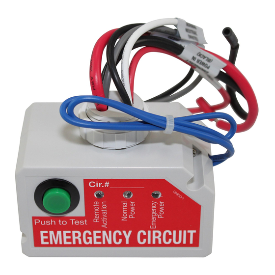
The ELCU-200-347 Emergency Lighting Control Unit allows lighting control devices for normal lighting to also control emergency
lighting installed within the area. The ELCU is designed for lighting control in areas where emergency lighting fixtures are connected
on dedicated emergency lighting circuits that are typically ON 24 hours per day. The ELCU allows ON/OFF control of the emergency
lighting along with the normal room lighting to save energy.
The intended operation of the ELCU is to guarantee that the emergency lighting is ON whenever normal power to the controlled circuit
is interrupted. While normal power is present, the ELCU allows control of the emergency lighting by a device such as an occupancy
sensor, a relay, a dimmer, or a wall switch.
Wiring Reference Table:
Emergency Power In
Emergency Neutral
Emergency Power Out
Normal Power Sense
Normal Neutral
Normal Switch Sense
When using electrical equipment always follow basic safety precautions, including:
• READ AND FOLLOW ALL SAFETY INSTRUCTIONS–SAVE THESE INSTRUCTIONS.
• Mount only to an approved electrical enclosure.
• Do not use near gas or electric heaters.
• Equipment should be mounted in locations and at heights where it will not readily be subjected to tampering by unauthorized
personnel.
• Use of accessory equipment not recommended by the manufacturer may cause an unsafe condition.
• Do not use this equipment for other than intended use.
DESCRIPTION AND OPERATION
AWG/Color
14 Black
18 Gray
14 Red
18 Black
18 White
18 Red
IMPORTANT SAFEGUARDS
Wattstopper
Emergency Lighting Control Unit
Dispositif de commande d'éclairage d'urgence
Unidad de control de iluminación de emergencia
Installation Instructions • Instructions d'Installation • Instrucciones de Instalación
SPECIFICATIONS
Voltages .............................................. 120–347VAC, 50/60Hz, single phase
Max Load Requirements
Ballast/ELV/MLV/Incandescent ...................................... 16A @120–347VAC
LED/E-Ballast/CFL ............................................................ 16A@120–277VAC
Motor ..................................................................... 1/4HP @120–347VAC
Plug Load ............................................................................15A @120VAC
Remote Activation ............................... 24VDC sourced, dry contact closure
Integral Control ................................................... Push-to-Test button on unit
Conformance ................UL924, NEC, OSHA, NFPA 101, "Life Safety Code,
.........................." Article700 of ANSI/NFPA 70, "National Electrical Code"
Operating Temperature ........................................ -4º to 131ºF (-20º to 55ºC)
Storage Temperature .......................................... -40º to 176ºF (-40º to 80ºC)
UL 2043 Plenum Rated
WARNING
TURN POWER OFF AT CIRCUIT
BREAKER BEFORE INSTALLING.
ONLY QUALIFIED ELECTRICIANS
SHOULD INSTALL THE ELCU-200-347.
®
Publicidad
Tabla de contenido

Resumen de contenidos para LEGRAND Wattstopper ELCU-200-347
- Página 1 Wattstopper ® Emergency Lighting Control Unit Dispositif de commande d’éclairage d’urgence Unidad de control de iluminación de emergencia No: 23038 – 10/17 rev. 3 Installation Instructions • Instructions d’Installation • Instrucciones de Instalación Catalog Number • Numéro de Catalogue • Número de Catálogo: ELCU-200-347 Country of Origin: Made in China •...
-
Página 2: Installation Procedure
CAUTION See instruction manual for installation, operation and - Fire alarm panel maintenance instructions - Security panel Emergency Line www.legrand.com/wattstopper • 800.879.8585 - Other 23033x1 “Always On” Emergency Lighting Emergency Neutral Alternate wiring for dimmer bypass on an emergency circuit... - Página 3 3. Connect the ELCU to the control device for the area controlled. Connect the ELCU’s Normal wiring leads to the normal lighting circuit as shown in the wiring diagram. Note that the Normal Power Sense connection should be made to the line side of the control device that serves the same area as the emergency lighting.
-
Página 4: Description Et Fonctionnement
- Panneau d'alarme incendie maintenance instructions 3. Si vous connectez des ELCU ensemble - Panneau de sécurité Circuit d'urgence www.legrand.com/wattstopper • 800.879.8585 23033x1 - Autre via leurs fils de boucle de test, vous «Toujours sur Marche» devez maintenir la polarité de leurs fils. -
Página 5: Procédure D'installation
16 A @120-277 VAC E-Ballast/CFL - Interrupteur de test CAUTION See instruction manual for installation, operation and - Panneau d'alarme incendie maintenance instructions - Panneau de sécurité www.legrand.com/wattstopper • 800.879.8585 - Autre 23033x1 Circuit d'urgence Éclairage Gradateur d'urgence «Toujours sur Marche»... -
Página 6: Descripción Y Funcionamiento
3. Mettez sur MARCHE le disjoncteur dans le panneau normal pour le circuit contrôlé. La DEL rouge s’allume, indiquant que l’alimentation normale est présente et que l’éclairage d’urgence n’est pas nécessaire. L’éclairage d’urgence doit se mettre sur ARRÊT. Confirmez la fonctionnalité de mise en MARCHE d’urgence automatique en mettant sur ARRÊT le disjoncteur du circuit normal. -
Página 7: Procedimiento De Instalación
- Panel de alarma de incendios maintenance instructions juntos, usando sus cables de prueba, - Panel de seguridad Línea de emergencia www.legrand.com/wattstopper • 800.879.8585 23033x1 - Otro asegúrese de mantener la polaridad "Siempre encendida" de los cables. -
Página 8: Instalación Del Dispositivo De Activación Remota Opcional
No. 23038 – 10/17 rev. 3 © Copyright 2017 Legrand All Rights Reserved. 800.879.8585 © Copyright 2017 Tous droits réservés Legrand. www.legrand.us/wattstopper © Copyright 2017 Legrand Todos los derechos reservados.


