
Manuales relacionados para De Dietrich VM iSystem - AD281

Resumen de contenidos para De Dietrich VM iSystem - AD281
- Página 1 FR - DE - EN - NL - IT - ES - PL - RU Régulation VM iSystem - AD281 Notice d'installation et d'entretien C003674-B Notice d'installation rapide 300027106-001-02 (0450281003)
- Página 2 La présence de ce logo sur le produit signifie la conformité de l’équipe ment avec les Directives de l’Union Européenne. The presence of this symbol on the product signifies that the equipment conforms with EU directives. Dieses Symbol am Produkt bedeutet, dass das Gerät den EU-Richtlinien entspricht De aanwezigheid van dit symbool op het product betekent dat de uitrus...
- Página 3 La présence de ce logo sur le produit indique qu'il ne doit pas être jeté avec les déchets ménagers mais orienté vers une structure de récupéra tion et de recyclage appropriée. The presence of this symbol on the product indicates that it must not be disposed of with household waste, but instead sent to appropriate recov...
-
Página 4: Description Des Touches
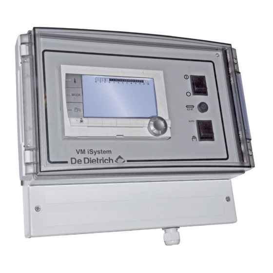
1. Description VM iSystem - AD281 Description Généralités La notice d'installation rapide est destinée au professionnel pour une installation et mise en service standard. ¼ Pour toute autre type d'installation ou pour plus d'informations, se référer à la notice d'installation et d'entretien et à la notice d'utilisation. -
Página 5: Raccordements Électriques
VM iSystem - AD281 2. Installation Installation Montage Le module VM iSystem peut être fixé au mur ou dans une armoire électrique. 1. Percer 3 trous. (1) Gabarit de perçage 2. Accrocher le module. 3. Ouvrir le capot de protection. -
Página 6: Accès Au Bornier De Raccordement
2. Installation VM iSystem - AD281 4 Italie : Les raccordements électriques doivent être conformes à la norme CEI. 4 Les indications des schémas électriques livrés avec la chaudière. 4 Les recommandations de la présente notice. ATTENTION Séparer les câbles de sondes des câbles 230 V. - Página 7 VM iSystem - AD281 2. Installation Raccordement du BUS cascade S.SYST Sonde système - Colis AD250 Câble BUS - Colis AD124 / AD134 / DB119 Commande à distance (Circuit C) - Colis AD254 / AD285 Sonde ECS - Colis AD212...
- Página 8 2. Installation VM iSystem - AD281 2.2.4. Régulation ou réseau de régulations VM iSystem raccordées à une ou plusieurs chaudières en cascade C003691-A (RX11) (RX11) 20... => 39 Sonde extérieure obligatoire Sondes extérieures facultatives Chaudière pilote Chaudières suiveuses VM iSystem 20...39...
- Página 9 VM iSystem - AD281 2. Installation 2.2.5. Raccordement de deux circuits chauffage et d'un ballon eau chaude sanitaire 0V + CDI C CDI B/ 0-10V/ ALIM S.SYST E.TEL 230V/50Hz C003685-D A Vanne 3 voies circuit B I Sonde ECS (Colis AD212) Ne pas utiliser le connecteur de simulation livré...
-
Página 10: Mise En Service
3. Mise en service VM iSystem - AD281 Mise en service Première mise sous tension 1. Appuyer sur la languette à ressort pour ouvrir le capot de protection. 2. Appuyer sur le bouton ON. 3. Appuyer sur le bouton AUTO. -
Página 11: Modification Des Réglages
VM iSystem - AD281 3. Mise en service Modification des réglages Le tableau de commande de la chaudière est réglé pour les installations de chauffage les plus courantes. Avec ces réglages, pratiquement toutes les installations de chauffage fonctionneront correctement. L'utilisateur ou l'installateur peut optimiser les paramètres selon ses besoins. - Página 12 3. Mise en service VM iSystem - AD281 11/10/2017 - 300027106-001-02 (0450281003)
- Página 13 Regelung VM iSystem - AD281 Installations- und Wartungsanleitung C003674-B Schnellinstallations- Anleitung 300027106-001-01 (0450281003)
-
Página 14: Allgemeine Angaben
1. Beschreibung VM iSystem - AD281 Beschreibung Allgemeine Angaben Die Schnellinstallationsanleitung ist für den Fachhandwerker für eine Standard-Installation und -Inbetriebnahme bestimmt. ¼ Für jeden anderen Anlagentyp bzw. weitere Informationen siehe die Installations- und Wartungsanleitung und die Bedienungsanleitung. WARNUNG Die Installation und die Inbetriebnahme darf nur durch einen qualifizierten Fachbetrieb erfolgen. -
Página 15: Elektrische Anschlüsse
VM iSystem - AD281 2. Anlage Anlage Montage Das VM iSystem-Modul kann an der Wand oder in einem Schaltschrank befestigt werden. 1. 3 Löcher bohren. (1) Bohrschablone 2. Das Modul befestigen. 3. Die Schutzabdeckung öffnen. 4. Die Einheit mit den 3 Schrauben befestigen. - Página 16 2. Anlage VM iSystem - AD281 4 Italien: Die elektrischen Anschlüsse müssen der Norm CEI entsprechen. 4 Die Angaben der mit dem Heizkessel gelieferten Schaltpläne. 4 Die Empfehlungen dieser Anleitung. ACHTUNG Fühler- und 230V-führende Kabel müssen voneinander getrennt verlegt werden.
- Página 17 VM iSystem - AD281 2. Anlage Anschluss des BUS Kaskadenschaltung S.SYST Systemfühler - Kolli AD250 Kabel BUS - Kolli AD124 / AD134 / DB119 Fernbedienung (Kreis C) - Kolli AD254 / AD285 WWE-Fühler - Kolli AD212 CDI C O r BF CDI B / CDR Fernbedienung (Kreis B) - Kolli AD254 / AD285 Außenfühler - Kolli FM46...
- Página 18 2. Anlage VM iSystem - AD281 2.2.4. Regelung oder VM iSystem Regelungsnetz an einen oder mehrere Heizkessel in Kaskadenschaltung angeschlossen C003691-A (RX11) (RX11) 20... => 39 Vorgeschriebener Außenfühler Außenfühler nach Wunsch Führungskessel Folgekessel VM iSystem 20...39 Das Schaltfeld des Heizkessels ist der Master des BUS. Die Funktion des/der Generators/en hängt vom vorliegenden Bedarf der...
- Página 19 VM iSystem - AD281 2. Anlage 2.2.5. Anschluss von zwei Heizungskreisen und einem Warmwasserspeicher 0V + CDI C CDI B/ 0-10V/ ALIM S.SYST E.TEL 230V/50Hz C003685-D A Dreiwegemischer Kreis B I WWE-Fühler (Kolli AD212) Der mit dem WWE-Fühler mitgelieferten Simulationsanschluss nicht benutzen.
- Página 20 3. Inbetriebnahme VM iSystem - AD281 Inbetriebnahme Erstmalige Einschaltung 1. Auf die gefederte Lasche drücken, um den Schutzdeckel zu öffnen. 2. Auf den Knopf ON drücken. 3. Auf den Knopf AUTO drücken. 4. Beim ersten Einschalten, wird das Menü SPRACHE angezeigt. Die gewünschte Sprache durch Drehen des Drehknopfs auswählen.
-
Página 21: Änderung Der Einstellungen
VM iSystem - AD281 3. Inbetriebnahme 7. Zum Bestätigen den Drehknopf drücken. 8. Die 2 Schrauben (geliefert im Beutel mit der Dokumentation) an der Vorderseite des Moduls anbringen, um die Schutzart IP21 zu garantieren. Änderung der Einstellungen Das Schaltfeld des Heizkessels ist für die häufigsten Heizungsanlagen voreingestellt. - Página 22 3. Inbetriebnahme VM iSystem - AD281 11/10/2017 - 300027106-001-02 (0450281003)
- Página 23 Regulation VM iSystem - AD281 Installation and Service Manual C003674-B Quick installation guide 300027106-001-01 (0450281003)
- Página 24 1. Description VM iSystem - AD281 Description General The quick installation instructions are intended for professionals for standard installation and commissioning. ¼ For all other types of installation or for more information, refer to the installation and service manual and the user guide.
-
Página 25: Electrical Connections
VM iSystem - AD281 2. Installation Installation Mounting The VM iSystem module can be affixed to the wall or in an electrical cabinet. 1. Drill 3 holes. (1) Drilling template 2. Affix the module. 3. Open the protective hood. 4. Secure the unit with the 3 screws. - Página 26 2. Installation VM iSystem - AD281 4 The recommendations in the instructions. CAUTION Separate the sensor cables from the 230 V cables. Use 2 pipes or cable guides at least 10 cm apart. Keep to the polarity shown on the terminals: phase (L), neutral (N) and earth *.
- Página 27 VM iSystem - AD281 2. Installation ALIM 230V/50Hz C003567-C L C Heating pump circuit C 3 way valve circuit B D.H.W. load pump Safety contact - Factory fitted bridge 3 way valve circuit C Auxiliary pump L AUX L B Heating pump circuit B...
- Página 28 2. Installation VM iSystem - AD281 2.2.4. VM iSystem control system or network of control systems connected to one or more boilers in cascade C003691-A (RX11) (RX11) 20... => 39 Compulsory outside sensor Optional outside sensors Master boiler Follower boilers VM iSystem 20...39...
- Página 29 VM iSystem - AD281 2. Installation 2.2.5. Connecting two circuits and a domestic hot water tank 0V + CDI C CDI B/ 0-10V/ ALIM S.SYST E.TEL 230V/50Hz C003685-D A 3 way valve circuit B I DHW sensor (Package AD212) Do not use the simulation connector delivered with the DHW sensor.
-
Página 30: Powering Up For The First Time
3. Commissioning VM iSystem - AD281 Commissioning Powering up for the first time 1. Press the spring-loaded tab to open the protective cover. 2. Press button ON. 3. Press button AUTO. 4. The first time the boiler is powered up, the LANGUAGE menu is displayed. -
Página 31: Changing The Settings
VM iSystem - AD281 3. Commissioning Changing the settings The boiler control panel is set for the most common heating systems. With these settings, practically all heating systems operate correctly. The user or installer can optimise the parameters according to own preferences. - Página 32 3. Commissioning VM iSystem - AD281 11/10/2017 - 300027106-001-02 (0450281003)
- Página 33 Regelaar VM iSystem - AD281 Installatie- en servicehandleiding C003674-B Snelle installatiehandleiding 300027106-001-01 (0450281003)
- Página 34 1. Beschrijving VM iSystem - AD281 Beschrijving Algemeen De snelle installatiehandleiding is bedoeld voor de vakman voor een standaard installatie en inbedrijfstelling. ¼ Zie voor alle andere soorten installatie of voor meer informatie de installatie- en onderhoudshandleiding en de gebruikshandleiding.
-
Página 35: Installatie
VM iSystem - AD281 2. Installatie Installatie Montage De module VM iSystem kan aan de muur of in een elektriciteitskast bevestigd worden. 1. Boor 3 gaten. (1) Boormal 2. Hang de module op. 3. Open de beschermkap. 4. Bevestig het geheel met de 3 schroeven. -
Página 36: Toegang Tot De Aansluitklemmenstrook
2. Installatie VM iSystem - AD281 4 Italië: De elektrische aansluitingen dienen te beantwoorden aan de norm CEI. 4 De aanwijzingen van de met de ketel meegeleverde elektrische schema's. 4 De aanbevelingen in de handleiding. OPGELET Scheid de sensorkabels van de 230V kabels. - Página 37 VM iSystem - AD281 2. Installatie Aansluiting van de cascade BUS S.SYST Systeemsensor - Colli AD250 Kabel BUS - Colli AD124 / AD134 / DB119 Afstandsbediening (Kring C) - Colli AD254 / AD285 SWW-sensor - Colli AD212 CDI C O...
- Página 38 2. Installatie VM iSystem - AD281 2.2.4. Regelaar of netwerk regelaars VM iSystem aangesloten op één of meerdere ketels in cascade C003691-A (RX11) (RX11) 20... => 39 Buitensensor verplicht Buitenvoelers facultatief Hoofdketel Volgketels VM iSystem 20...39 Het bedieningspaneel van de verwarmingsketel bestuurt de BUS. De werking van de generator(en) hangt af van de werkelijke behoeften van de secundaire kringen.
- Página 39 VM iSystem - AD281 2. Installatie 2.2.5. Aansluiting van twee kringen en een SWW- boiler 0V + CDI C CDI B/ 0-10V/ ALIM S.SYST E.TEL 230V/50Hz C003685-D A Driewegklep kring B I SWW-sensor (Colli AD212) Niet de met de SWW-voeler meegeleverde simulatiestekker gebruiken.
-
Página 40: Inbedrijfstelling
3. Inbedrijfstelling VM iSystem - AD281 Inbedrijfstelling Eerste keer onder spanning brengen 1. Druk op het verende lipje om de beschermkap te openen. 2. Druk op knop ON. 3. Druk op knop AUTO. 4. Bij de eerste keer onder spanning, het menu TAAL wordt weergegeven. -
Página 41: Instellingen Wijzigen
VM iSystem - AD281 3. Inbedrijfstelling 8. Plaats de 2 schroeven (meegeleverd in het zakje met documentatie) aan de voorzijde van de module om de beveiligingsindex IP21 te garanderen. Instellingen wijzigen De bedieningsautomaat van de ketel is ingesteld op de meest voorkomende cv-installaties. - Página 42 3. Inbedrijfstelling VM iSystem - AD281 11/10/2017 - 300027106-001-02 (0450281003)
-
Página 43: Istruzioni Per L'installazione E La Manutenzione
Regolazione VM iSystem - AD281 Istruzioni per l'installazione e la manutenzione C003674-B Istruzioni d'installazione rapida 300027106-001-01 (0450281003) -
Página 44: Descrizione Dei Tasti
1. Descrizione VM iSystem - AD281 Descrizione Generalità Il manuale di installazione rapida è destinato al professionista per il montaggio e la messa in funzione standard. ¼ Per qualunque altro tipo di impianto o per maggiori informazioni, fare riferimento al manuale di installazione/manutenzione e al manuale di utilizzo. -
Página 45: Collegamenti Elettrici
VM iSystem - AD281 2. Installazione Installazione Montaggio Il modulo VM iSystem può essere fissato al muro o in un armadio elettrico. 1. Realizzare 3 fori. (1) Maschera di foratura 2. Agganciare il modulo. 3. Aprire il coperchio di protezione. - Página 46 2. Installazione VM iSystem - AD281 4 Italia: I collegamenti elettrici devono essere conformi alla norma CEI. 4 Le indicazioni degli schemi elettrici in dotazione con la caldaia. 4 Le raccomandazioni contenute nelle istruzioni. ATTENZIONE Tenere i cavi delle sonde separati dai cavi 230 V.
- Página 47 VM iSystem - AD281 2. Installazione Collegamento del BUS cascata S.SYST Sonda sistema - Collo AD250 Cavo BUS - Collo AD124 / AD134 / DB119 Comando a distanza (Circuito C) - Collo AD254 / AD285 Sonda ACS - Collo AD212...
- Página 48 2. Installazione VM iSystem - AD281 2.2.4. Regolazione o rete di regolazioni VM iSystem collegate ad una o più caldaie a cascata C003691-A (RX11) (RX11) 20... => 39 Sonda esterna obbligatoria Sonde esterne facoltative Caldaia master Caldaie slave VM iSystem 20...39...
- Página 49 VM iSystem - AD281 2. Installazione 2.2.5. Collegamento di due circuiti e di un bollitore acqua calda sanitaria 0V + CDI C CDI B/ 0-10V/ ALIM S.SYST E.TEL 230V/50Hz C003685-D A Valvola a 3 vie circuito B I Sonda ACS (Collo AD212) Non utilizzare il connettore di simulazione fornito con la sonde ECS.
-
Página 50: Prima Messa In Tensione
3. Messa in servizio VM iSystem - AD281 Messa in servizio Prima messa in tensione 1. Premere la linguetta a molla per aprire il coperchio di protezione. 2. Premere il pulsante ON. 3. Premere il pulsante AUTO. 4. Alla prima alimentazione, il menù LINGUA è visualizzato. -
Página 51: Modifica Delle Impostazioni
VM iSystem - AD281 3. Messa in servizio 8. Montare le 2 viti (incluse nel sacchetto della documentazione) nella parte anteriore del modulo per garantire l'indice di protezione IP21. Modifica delle impostazioni La scheda di comando della caldaia è programmata per gli impianti di riscaldamento ordinari. - Página 52 3. Messa in servizio VM iSystem - AD281 11/10/2017 - 300027106-001-02 (0450281003)
- Página 53 Regulación VM iSystem - AD281 Instrucciones de instalación y de mantenimiento C003674-B La guía de instalación rápida 300027106-001-01 (0450281003)
-
Página 54: Generalidades
1. Descripción VM iSystem - AD281 Descripción Generalidades La guía de instalación rápida, dirigida al profesional, se emplea para efectuar una instalación y una puesta en servicio estándar. ¼ Para cualquier otro tipo de instalación o para obtener más información, consultar las instrucciones de instalación y mantenimiento y las instrucciones de uso. -
Página 55: Instalación
VM iSystem - AD281 2. Instalación Instalación Montaje El módulo VM iSystem se puede fijar a la pared o dentro de un armario eléctrico de distribución. 1. Hacer 3 agujeros. (1) Plantilla de taladrado 2. Colgar el módulo. 3. Abrir la tapa de protección. -
Página 56: Acceso Al Bornero De Conexiones
2. Instalación VM iSystem - AD281 4 Italia: Las conexiones eléctricas deben estar conformes con la norma CEI. 4 Las indicaciones de los esquemas eléctricos suministrados con la caldera. 4 Las recomendaciones de las instrucciones. ATENCION Separar los cables de sondas de los cables de 230 V. - Página 57 VM iSystem - AD281 2. Instalación Conexión del BUS cascada S.SYST Sonda de sistema - Bulto AD250 Cable BUS - Bulto AD124 / AD134 / DB119 Mando a distancia (Circuito C) - Bulto AD254 / AD285 Sonda a.c.s. - Bulto AD212...
-
Página 58: Regulación O Red De Regulaciones Vm Isystem Conectadas A Una O Varias Calderas En Cascada
2. Instalación VM iSystem - AD281 2.2.4. Regulación o red de regulaciones VM iSystem conectadas a una o varias calderas en cascada C003691-A (RX11) (RX11) 20... => 39 Sonda exterior obligatoria Sondas exteriores facultativas Caldera maestra Calderas esclava VM iSystem 20...39... -
Página 59: Conexión De Dos Circuitos Y Un Acumulador De Agua Caliente Sanitaria
VM iSystem - AD281 2. Instalación 2.2.5. Conexión de dos circuitos y un acumulador de agua caliente sanitaria 0V + CDI C CDI B/ 0-10V/ ALIM S.SYST E.TEL 230V/50Hz C003685-D A Válvula 3 vías circuito B I Sonda a.c.s. (Bulto AD212) No utilizar el conector de simulación suministrado con la sonda de ACS. -
Página 60: Primera Puesta En Tensión
3. Puesta en marcha VM iSystem - AD281 Puesta en marcha Primera puesta en tensión 1. Apretar la lengüeta de muelle para abrir la cubierta de protección. 2. Pulsar el botón ON. 3. Pulsar el botón AUTO. 4. La primera vez que se enciende aparece el menú IDIOMA. -
Página 61: Modificación De Los Ajustes
VM iSystem - AD281 3. Puesta en marcha 8. Colocar los 2 tornillos (suministrados en la bolsa de la documentación) en la parte delantera del módulo para garantizar el índice de protección IP21. Modificación de los ajustes El cuadro de mando de la caldera viene configurado para las instalaciones de calefacción más habituales. - Página 62 3. Puesta en marcha VM iSystem - AD281 11/10/2017 - 300027106-001-02 (0450281003)
- Página 63 Regulator VM iSystem - AD281 Instrukcja instalowania i konserwacji C003674-B Instrukcja szybkiej instalacji 300027106-001-01 (0450281003)
-
Página 64: Informacje Ogólne
1. Opis VM iSystem - AD281 Opis Informacje ogólne Instrukcje szybkiej instalacji są przeznaczone dla uprawnionych instalatorów dla standardowego instalowania i uruchomienia. ¼ Dla każdego innego typu instalacji lub dalszych informacji patrz Instrukcja instalowania i konserwacji oraz Instrukcja obsługi. OSTRZEŻENIE Instalacja i uruchomienie muszą... -
Página 65: Podłączenia Elektryczne
VM iSystem - AD281 2. Instalacja Instalacja Montaż Moduł VM iSystem może być zamontowany na ścianie lub w szafce rozdzielczej. 1. Wywiercić 3 otwory. (1) Szablon otworów do wywiercenia 2. Zamocować moduł. 3. Zdjąć osłonę zabezpieczającą. 4. Przykręcić zespół 3 śrubami. - Página 66 2. Instalacja VM iSystem - AD281 4 Włochy: Podłączenia elektryczne muszą być zgodne z normą CEI. 4 Danych zawartych na dostarczonych z kotłem schematach połączeń elektrycznych. 4 Zaleceń zawartych w tej instrukcji. UWAGA Kable czujników oraz pod napięciem 230V muszą być...
- Página 67 VM iSystem - AD281 2. Instalacja Podłączenie magistrali BUS w instalacji kaskadowej S.SYST Czujnik systemu - Pakiet AD250 Kabel BUS - Pakiet AD124 / AD134 / DB119 Zdalne sterowanie (Obieg C) - Pakiet AD254 / AD285 Czujnik c.w.u. - Pakiet AD212...
- Página 68 2. Instalacja VM iSystem - AD281 2.2.4. Regulator lub sieć regulatorów VM iSystem podłączona do jednego lub wielu kotłów w kaskadzie C003691-A (RX11) (RX11) 20... => 39 Obowiązkowy czujnik zewnętrzny Czujnik temperatury zewnętrznej na życzenie Kocioł prowadzący Kotły podrzędne VM iSystem 20...39...
- Página 69 VM iSystem - AD281 2. Instalacja 2.2.5. Podłączenie dwóch obiegów i podgrzewacza c.w.u. 0V + CDI C CDI B/ 0-10V/ ALIM S.SYST E.TEL 230V/50Hz C003685-D A 3-drogowy zawór mieszający obiegu B I Czujnik c.w.u. (Pakiet AD212) Nie używać wtyku symulacji dostarczonego z czujnikiem c.w.u..
- Página 70 3. Uruchomienie VM iSystem - AD281 Uruchomienie Pierwsze załączenie 1. Aby otworzyć pokrywę ochronną nacisnąć na języczek sprężynowy. 2. Nacisnąć na przycisk ON. 3. Nacisnąć na przycisk AUTO. 4. Przy pierwszym załączeniu wyświetlone zostanie menu JEZYK. Wybrać żądany język poprzez obracanie pokrętłem.
- Página 71 VM iSystem - AD281 3. Uruchomienie 8. Dla zapewnienia rodzaju ochrony IP21 umieścić z przodu modułu 2 śruby (dostarczone w torbie z dokumentacją). Zmiana nastaw Konsola sterownicza kotła jest nastawiona na najczęściej występujące rodzaje instalacji grzewczych. Przy tych nastawach pracują prawidłowo praktycznie wszystkie instalacje.
- Página 72 3. Uruchomienie VM iSystem - AD281 11/10/2017 - 300027106-001-02 (0450281003)
- Página 73 Система регулирования VM iSystem - AD281 Инструкция по установке и техническому обслуживанию C003674-B Инструкция по быстрой установке 300027106-001-01 (0450281003)
-
Página 74: Общие Сведения
1. Описание VM iSystem - AD281 Описание Общие сведения Краткая инструкция по установке предназначена для стандартного ввода в эксплуатацию квалифицированным специалистом. ¼ Для любого другого типа установки и для большей информации см. инструкцию по установке и техническому обслуживанию, а также инструкцию по эксплуатации. -
Página 75: Электрические Подключения
VM iSystem - AD281 2. Установка Установка Монтаж Модуль VM iSystem может быть закреплен на стене или в электрическом шкафу. 1. Просверлить 3 отверстия. (1) Лекало для просверливания 2. Навесить модуль. 3. Открыть защитную крышку. 4. Закрепить систему при помощи 3 винтов. - Página 76 2. Установка VM iSystem - AD281 4 Италия : Электрические подключения должны соответствовать стандарту CEI. 4 Обозначения электрических схем, поставляемых с котел. 4 Рекомендации инструкции. ВНИМАНИЕ Отделить кабели датчиков от кабелей 230 В. использовать 2 кабельных канала или кабелепровода, расположенных на расстоянии, как...
- Página 77 VM iSystem - AD281 2. Установка Подключение кабеля BUS каскада S.SYST Датчик системы - Ед. поставки AD250 Кабель BUS - Ед. поставки AD124 / AD134 / DB119 Дистанционное управление (контур C) - Ед. Датчик ГВС - Ед. поставки AD212 CDI C O r BF поставки...
- Página 78 2. Установка VM iSystem - AD281 2.2.4. Один модуль или сеть модулей VM iSystem , подключенных к одному котлу или каскаду котлов C003691-A (RX11) (RX11) 20... => 39 Обязательный датчик наружной температуры Необязательные датчики наружной температуры Ведущий котел Ведомые котлы...
- Página 79 VM iSystem - AD281 2. Установка 2.2.5. Подключение 2 контуров и водонагревателя горячей санитарно- технической воды CDI C CDI B/ 0V + 0-10V/ ALIM S.SYST E.TEL 230V/50Hz C003685-D A 3-ходовой клапан контура B I Датчик ГВС (Ед. поставки AD212) Не использовать разъём для симуляции из комплекта...
-
Página 80: Ввод В Эксплуатацию
3. Ввод в эксплуатацию VM iSystem - AD281 Ввод в эксплуатацию Первое включение 1. Нажать на защёлку с пружиной, чтобы открыть защитную крышку. 2. Нажать на кнопку ON. 3. Нажать на кнопку AUTO. 4. Во время первого включения отображается меню ЯЗЫК. -
Página 81: Изменение Настроек
VM iSystem - AD281 3. Ввод в эксплуатацию Параметры Описание Совместная работа с панелями управления Diematic - Нет VM/MR приоритета ГВС. Если параметр КОНФИГУРАЦИЯ установлен на VM/ MR : Удерживать нажатой клавишу - в течение 5 секунд. Выбрать меню #СИСТЕМА. - Página 82 3. Ввод в эксплуатацию VM iSystem - AD281 Неисправности В случае обнаружения неисправности во время работы на дисплее модуля мигает VM iSystem и отображается сообщение об ошибке и соответствующий код. 1. Записать отображаемый код. Код очень важен для быстрого и корректного выявления типа...
- Página 84 DE DIETRICH THERMIQUE S.A.S 129164, Россия, г. Москва Зубарев переулок, д. 15/1 Бизнес-центр «Чайка Плаза», офис 309 +7 (495) 221-31-51 DUEDI S.r.l. DE DIETRICH THERMIQUE Iberia S.L.U. www.duediclima.it www.dedietrich-calefaccion.es Distributore Ufficiale Esclusivo Av. Princep d’Astúries 43-45 De Dietrich-Thermique Italia 08012 BARCELONA...