Tabla de contenido
Publicidad
Idiomas disponibles
Idiomas disponibles
Enlaces rápidos
S
TAR
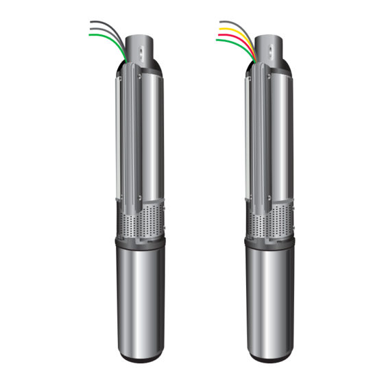
2 Wire Plus Ground
Questions, problems, missing parts? Before returning to your retailer, call our
customer service department at 1-800-742-5044, 7:30 a.m.-5:00 p.m., EST,
Monday-Friday.
4 INCH SUBMERSIBLE WELL PUMP
®
3 Wire Plus Ground
IL0655
MODELS:
4H05A05001
4H05A05005
4H05A05301
4H05A05305
4H05A07301
4H05A07305
4H05A10301
4H05A10305
4H05A15301
4H07G05005
4H07G05301
4H07G05305
4H10A05001
4H10A05005
4H10A05301
4H10A05305
4H10A07301
4H10A07305
4H10A10301
4H10A10305
4H10A15301
4H10A15305
IL0656
2 & 3 Wire
Español p. 30
4H10A20301
4H10G05001
4H10G05005
4H10G05301
4H10G05305
4H10G07301
4H10G07305
4H10G10301
4H10G10305
4H19A05001
4H19A05305
4H19A07301
4H19A07305
4H19A10301
4H19A10305
4H19A15301
4H19A15305
4H19A20301
4H19A30301
4H19G10301
4H19G10305
130583 D
Publicidad
Capítulos
Tabla de contenido
Solución de problemas

Manuales relacionados para Star 4H05A05001

Resumen de contenidos para Star 4H05A05001
- Página 1 4 INCH SUBMERSIBLE WELL PUMP 2 & 3 Wire ® Español p. 30 2 Wire Plus Ground 3 Wire Plus Ground MODELS: 4H05A05001 4H10A20301 4H05A05005 4H10G05001 4H05A05301 4H10G05005 4H05A05305 4H10G05301 4H05A07301 4H10G05305 4H05A07305 4H10G07301 4H05A10301 4H10G07305 4H05A10305 4H10G10301 4H05A15301 4H10G10305...
-
Página 2: Tabla De Contenido
RISK OF ELECTRIC SHOCK Failure to do so could result in fatal electrical These pumps have not been investigated for use shock. in swimming pool areas. Copyright © 2011 Star Water Systems. All rights reserved. -
Página 3: Electrical Shock Hazard
NOTE: Install all electrical equipment in protected area to provide adequate ventilation for pressure switch and controls to prevent moisture damage to components. NOTE: Install pump, pressure tank, pitless adaptor or well seal in accordance with state and local plumbing codes. Copyright © 2011 Star Water Systems. All rights reserved. -
Página 4: Preparation
(grounding) for additional information. adaptor for use with poly pipe, cable guards NOTE: All wiring should be done by a qualified to protect wire inside the well, thread tape and electrician. thread paste. Copyright © 2011 Star Water Systems. All rights reserved. - Página 5 1 outside fixture, the total fixture count is 11. Your pump should provide 10 GPM per the chart above. Typical 3 - 4 bedroom homes require 8 - 12 GPM. Copyright © 2011 Star Water Systems. All rights reserved.
- Página 6 WARNING: 3-WIRE SUBMERSIBLES ONLY: This submersible pump must be wired directly to a Franklin control box of the same horsepower and voltage rating in order to work properly. IT MUST BE USED WITH WITH A CONTROL BOX. Copyright © 2011 Star Water Systems. All rights reserved.
- Página 7 1-1/2 230 4H10A07301 4H19A15305 1-1/2 230 4H10A07305 4H19A20301 4H10A10301 4H19A30301 4H10A10305 4H19G10301 4H10A15301 1-1/2 230 4H19G10305 4H10A15305 1-1/2 230 *NOTE: Wire length is the total distance from power source to pump depth. Copyright © 2011 Star Water Systems. All rights reserved.
-
Página 8: Assembly Instructions
NOTE: All threaded joints and connections should have thread tape (not included) applied, tightened securely with a pipe wrench (not included) and then tightened an additional 1/4 turn. Copyright © 2011 Star Water Systems. All rights reserved. - Página 9 If using barbed 1 in. black poly pipe, install a 1-1/4 in. x adapter 1 in. reducer bushing (sold separately) as shown. (Fig. 2a) 1-1/4 in x 1 in. reducer bushing Copyright © 2011 Star Water Systems. All rights reserved.
- Página 10 Electrical cable - connects to house Torque Arrestor electricity Drop Pipe Torque arrestor - keeps pump stable Well Casing Drop pipe - connects pump to discharge Well casing - holds all components Copyright © 2011 Star Water Systems. All rights reserved.
-
Página 11: Electrical Hookup At The Pump
Then slide stripped end of wire from electrical cable into other end of metal connector. Connector should be centered over both wires. Squeeze metal connector until it closes tightly over both wire ends. (Fig 2) Copyright © 2011 Star Water Systems. All rights reserved. - Página 12 A cable guard or plastic zip ties may also be used. (Fig 5) Ground Wire Installation (REQUIRED) DANGER: The green ground wire from Pump motor must be connected to power supply ground or fatal electrical shock may result. Copyright © 2011 Star Water Systems. All rights reserved.
-
Página 13: Installation Instructions
(Fig 2) Top of Well Screen 10 Ft. Min. Bottom of Well 3. Use a pipe vise (not included) to prevent the pump and pipe from dropping into the well. (Fig 3) Copyright © 2011 Star Water Systems. All rights reserved. - Página 14 4b. Well Seal Installation: After the pump assembly is lowered into the well, mount the well seal onto the well casing and tighten the four bolts in the well seal evenly. (Fig. 4b) IL1148 Copyright © 2011 Star Water Systems. All rights reserved.
-
Página 15: Preliminary Test Run
(Fig. 3) NOTE: If the well is low capacity, use a low 20 Ft. water level control. Top of Well Screen 10 Ft. Min. Bottom of Well Copyright © 2011 Star Water Systems. All rights reserved. -
Página 16: Pressure Tank Installation Instructions
(Fig. 2) IL1149 3. Connect a 3/4 in. fitting (sold separately) to the 3/4 in. opening on the pipe tee. (Fig. 3) Tape IL1153 Copyright © 2011 Star Water Systems. All rights reserved. - Página 17 (all sold separately) as needed for your particular installation. (Fig. 5) IL1154 Glue 6. Connect a drain valve (sold separately) to one of the 1/2 in. openings in the tank tee. (Fig. 6) Tape Copyright © 2011 Star Water Systems. All rights reserved.
- Página 18 Tape IL115 9. Add additional couplings, unions and pipe (all sold separately) as necessary to reach the pump. (Fig. 9) 50 60 NOTE: Schedule 80 pipe recommended Schedule 80 Pipe Shown Copyright © 2011 Star Water Systems. All rights reserved.
-
Página 19: Electrical Hookup From The House To Pump And Pressure Tank
(sold separately) to pressure switch. (Fig. 1) IL1170 2. Remove cover from pressure switch and screw the switch into the 1/4 in. opening on the top of the pipe tee. (Fig. 2) Copyright © 2011 Star Water Systems. All rights reserved. -
Página 20: Strain Relief
5. Thread the cable from the pump through the remaining hole in the side of the pressure switch and tighten down the electric wire strain relief. CAUTION: Do not crush wire. Copyright © 2011 Star Water Systems. All rights reserved. - Página 21 7. Connect green ground wires from the pump cable and the house electric cable to the two ground green screws on base of pressure switch. Replace switch cover. (Fig 7) From From Power Source Pump Ground Screws Copyright © 2011 Star Water Systems. All rights reserved.
- Página 22 2. Remove the cover from the control box (sold separately) and mount it in an indoor location protected from moisture. (Fig. 2) Terminal Terminal Terminal Terminal Terminal Green Green Ground Ground Screw Screw Copyright © 2011 Star Water Systems. All rights reserved.
- Página 23 “B”, “Y” and “R”. (Fig. 4) 5. Connect the green ground wire from the pump to the green ground screw in the lower right corner of the control box. (Fig. 5) IL117 Copyright © 2011 Star Water Systems. All rights reserved.
- Página 24 8. Connect the green ground wire from the IL1179 pressure switch to the green ground screw in the lower left corner of the control box and re-install the control box cover. (Fig. 8) IL1180 Copyright © 2011 Star Water Systems. All rights reserved.
- Página 25 CAUTION: Do not crush wire. (Fig. 10) Strain Relief 1. Connect the two wires from the house IL1162 electrical service to the outside pressure switch terminals (L1 and L4). (Fig. 11) Copyright © 2011 Star Water Systems. All rights reserved.
- Página 26 Replace switch cover. (Fig 14) From From Power Source Control Box IL1182 Ground Screws Copyright © 2011 Star Water Systems. All rights reserved.
-
Página 27: Troubleshooting
Make necessary corrections 2. Defective drop cable or motor 2. Check motor winding resistance. Pump must be pulled to replace defective cable or motor Copyright © 2011 Star Water Systems. All rights reserved. - Página 28 3. Leak in drop pipe or worn pump 3. Throttle pump output at gate valve or readjust pressure switch to lower shut off pressure setting. If pump does not shut off, pump must be raised and defect repaired Copyright © 2011 Star Water Systems. All rights reserved.
- Página 29 28 lbs. 3. Check valve defect or leak in drop pipe 3. Throttle pump output at gate valve. If pump does not shut off, pump must be raised and defect repaired Copyright © 2011 Star Water Systems. All rights reserved.
-
Página 30: Bomba Para Pozos Sumergible De 10,16 Cm
¿Preguntas, problemas, piezas faltantes? Antes de volver a la tienda, comuníquese con nuestro Departamento de Servicio al Cliente al 1-800-742-5044, de lunes a viernes de 7:30 a.m. a 5:00 p.m., hora estándar del Este. 130583S D © 2011 Star Water Systems. Reservados todos los derechos. -
Página 31: Riesgo De Descarga Eléctrica
No manipule la bomba con las manos húmedas ni cuando esté parado en el agua, ya que podría ocurrir una descarga eléctrica fatal. SIN IMPORTAR EL MOTIVO, desconecte la alimentación principal antes de manipular la unidad. © 2011 Star Water Systems. Reservados todos los derechos. -
Página 32: Información De Seguridad
NOTA: Instale el adaptador desmontable del tanque de presión de la bomba o el sello para pozos de acuerdo con los códigos de plomería estatales y locales. © 2011 Star Water Systems. Reservados todos los derechos. -
Página 33: Preparación
Código Eléctrico Nacional polietileno, protectores de cable para proteger los (NEC). cables del interior del pozo, cinta para roscas y pasta NOTA: Todo el cableado debe realizarlo un para roscas. electricista calificado. © 2011 Star Water Systems. Reservados todos los derechos. -
Página 34: Cuadro A De Rendimiento De La Bomba
2 baños, más 3 juegos en la cocina y 1 juego en el exterior de la casa, en total tiene 10 juegos de grifería. Según el cuadro anterior, la bomba debe suministrar 10 GPM. Los hogares típicos con 3 o 4 habitaciones requieren entre 8 y 12 GPM. © 2011 Star Water Systems. Reservados todos los derechos. - Página 35 Franklin que tenga la misma clasificación de caballaje y voltaje, para que funcione adecuadamente. DEBE USARSE CON UN A CAJA DE CONTROL. © 2011 Star Water Systems. Reservados todos los derechos.
- Página 36 Reste 3,05 m a la profundidad de su pozo. Consulte la tabla de rendimiento de la página para asegurarse de que la bomba sea apta para esta profundidad. (Fig. 1) © 2011 Star Water Systems. Reservados todos los derechos.
-
Página 37: Instrucciones De Ensamblaje
Si se trata de un tubo de 1”, también necesitará una boquilla reductora de 1-1/4” x 1” (no se muestra en la imagen). (Fig. 1a) © 2011 Star Water Systems. Reservados todos los derechos. - Página 38 (Fig. 2a) Boquilla reductora de 1-1/4” x 1” 2b. Sujete el tubo en el extremo dentado del adaptador macho con dos abrazaderas de manguera (se venden por separado). IL1171 (Fig. 2b) © 2011 Star Water Systems. Reservados todos los derechos. IL1172...
-
Página 39: Conexión Eléctrica A La Bomba
PRECAUCIÓN: Siga las instrucciones cuidadosamente para hacer un empalme impermeable. Si el empalme tiene pérdidas, la bomba puede dañarse, los fusibles pueden fundirse, el protector contra sobrecargas puede desconectarse o puede producirse una descarga eléctrica. © 2011 Star Water Systems. Reservados todos los derechos. - Página 40 Apriete el conector de metal hasta que se cierre firmemente en ambos extremos del cable. (Fig. 2) 3. Deslice un tubo contraíble sobre cada junta Conector de metal corrugada. (Fig. 3) Tubo contraíble IL1145 © 2011 Star Water Systems. Reservados todos los derechos.
- Página 41 RECORDATORIO: La bomba y toda la tubería se deben ensamblar y conectar de manera segura antes de descender el ensamble hacia el interior del pozo. © 2011 Star Water Systems. Reservados todos los derechos.
-
Página 42: Instrucciones De Instalación
Parte inferior del pozo 3. Use una prensa para tuberías (no se incluye) para evitar que la bomba y el tubo se caigan en el pozo. (Fig. 3) © 2011 Star Water Systems. Reservados todos los derechos. - Página 43 (Fig. 4b) IL1148 © 2011 Star Water Systems. Reservados todos los derechos.
-
Página 44: Ejecución De Prueba Preliminar
6,10 m NOTA: Si el pozo tiene poca capacidad, use un control de nivel bajo de agua. Parte superior de 3,05 m (mínimo) la malla del pozo Parte inferior del pozo © 2011 Star Water Systems. Reservados todos los derechos. -
Página 45: Instrucciones De Instalación Del Tanque De Presión
T del tanque (se vende por separado) a través de IL1149 la abertura en la parte inferior del tanque de presión. Luego, apriete firmemente. (Fig. 2) © 2011 Star Water Systems. Reservados todos los derechos. - Página 46 3/4”. (Fig. 4) Pegamento 5. Conecte los codos, la tubería adicional y la válvula de bola (todo se vende por separado), según sea necesario para su instalación en IL1154 particular. (Fig. 5) Pegamento © 2011 Star Water Systems. Reservados todos los derechos.
- Página 47 8. Para conectar el tanque de presión a la bomba (A), comience ajustando un acoplador de 1” (se vende por separado) en la tubería en T. (Fig. 8) 50 60 Cinta IL115 © 2011 Star Water Systems. Reservados todos los derechos.
-
Página 48: Conexión Eléctrica De La Casa A La Bomba Y Al Tanque De Presión
1. Determine el voltaje adecuado de la caja de interruptores (se vende por separado) al interruptor de presión. (Fig. 1) IL1170 © 2011 Star Water Systems. Reservados todos los derechos. - Página 49 PRECAUCIÓN: No aplaste el cable. (Fig. 3) Aliviador de tensión 4. Conecte los dos cables del servicio eléctrico de la casa a las terminales del interruptor de presión IL1162 externas (L1 y L4). (Fig. 4) © 2011 Star Water Systems. Reservados todos los derechos.
- Página 50 Reemplace la tapa del interruptor. (Fig. 7) De la fuente De la de alimentación bomba Tornillos de puesta a tierra © 2011 Star Water Systems. Reservados todos los derechos.
- Página 51 área bajo techo protegida de la humedad. (Fig. 2) Terminal Terminal Terminal Terminal Terminal Tornillo Tornillo verde de verde de puesta puesta a tierra a tierra © 2011 Star Water Systems. Reservados todos los derechos.
- Página 52 “Y” y “R”. (Fig. 4) 5. Conecte el conductor de tierra verde de la bomba al tornillo verde de puesta a tierra en la esquina inferior derecha de la caja de control. (Fig. 5) IL117 © 2011 Star Water Systems. Reservados todos los derechos.
- Página 53 (Fig. 8) IL1180 © 2011 Star Water Systems. Reservados todos los derechos.
- Página 54 PRECAUCIÓN: No aplaste el cable. (Fig. 10) Aliviador de tensión 11. Conecte los dos cables del servicio eléctrico de IL1162 la casa a las terminales del interruptor de presión externas (L1 y L4). (Fig. 11) © 2011 Star Water Systems. Reservados todos los derechos.
- Página 55 Reemplace la tapa del interruptor. (Fig. 14). De la fuente De la caja de alimentación de control IL1182 Tornillos de puesta a tierra © 2011 Star Water Systems. Reservados todos los derechos.
-
Página 56: Solución De Problemas
2. El motor o el cable de bajada están 2. Revise la resistencia del bobinado defectuosos. del motor. Será necesario sacar la bomba del pozo para reemplazar el motor o el cable defectuoso. © 2011 Star Water Systems. Reservados todos los derechos. - Página 57 8. El eje del motor o el eje de la bomba 8. Saque la bomba, inspeccione están rotos o el acoplador está los ejes y el acoplador en desgastado. busca de daños. Reemplace los componentes defectuosos. © 2011 Star Water Systems. Reservados todos los derechos.
- Página 58 3. Regule la salida de la bomba hay una fuga en el tubo de salida. con la válvula de compuerta. Si la bomba no se apaga, será necesario sacarla y reparar el defecto. © 2011 Star Water Systems. Reservados todos los derechos.