Tabla de contenido
Publicidad
Idiomas disponibles
Idiomas disponibles
Enlaces rápidos
Harbor Breeze® is a registered trademark
of LF, LLC. All Rights Reserved.
ATTACH YOUR RECEIPT HERE
Serial Number _________________________
Questions, problems, missing parts? Before returning to your retailer, call our customer
service department at 1-800-643-0067, 8 a.m. - 6 p.m., EST, Monday - Thursday, 8 a.m. - 5 p.m.,
EST, Friday. p.m., EST, Monday - Friday.
XXXXX
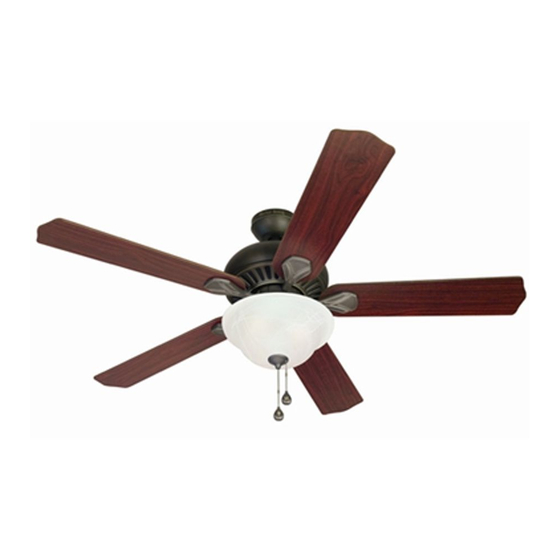
CROSSWINDS CEILING FAN
Purchase Date _________________________
1
ITEM #0044687, 0043676, 0044622
MODEL #40093, 40091, 40092
Lowes.com/harborbreeze
Español p. 25
Publicidad
Capítulos
Tabla de contenido
Solución de problemas

Manuales relacionados para Harbor Breeze 40093


Resumen de contenidos para Harbor Breeze 40093
- Página 1 ITEM #0044687, 0043676, 0044622 CROSSWINDS CEILING FAN MODEL #40093, 40091, 40092 Español p. 25 Harbor Breeze® is a registered trademark of LF, LLC. All Rights Reserved. ATTACH YOUR RECEIPT HERE Serial Number _________________________ Purchase Date _________________________ Questions, problems, missing parts? Before returning to your retailer, call our customer service department at 1-800-643-0067, 8 a.m.
-
Página 2: Tabla De Contenido
TABLE OF CONTENTS Package Contents ..............3 Hardware Contents . -
Página 3: Package Contents
PACKAGE CONTENTS PART DESCRIPTION QUANTITY Downrod Plastic Plug Button (preassembled to Switch Housing Cap (Q)) Canopy (preassembled to the Mounting Bracket (D)) Mounting Bracket Light Kit Motor Assembly Blade Arm Blade Bowl Bulb End Cap (preassembled to Light Kit (E)) Finial (preassembled to Light Kit (E)) Canopy Cover (preassembled to Canopy (C)) Remote Control... -
Página 4: Hardware Contents
HARDWARE CONTENTS Motor Screw Wire Pull Chain Downrod Clip Downrod Pin Qty. 10 Connector Extension Qty. 1 Qty. 1 (preassembled to Qty. 5 Qty. 2 (preassembled to (preassembled to Motor Assembly + 1 extra Downrod (A)) Downrod (A)) (F)) + 1 extra Motor Housing Set Closemount Screw Mounting Bracket... -
Página 5: Safety Information
SAFETY INFORMATION Please read and understand this entire manual before attempting to assemble, operate, or install the product. • Before you begin installing the fan, disconnect the power by removing fuses or turning off the circuit breakers. • Make sure that all electrical connections comply with local codes, ordinances, the National Electrical Code, and ANSI/NFPA 70-199. Hire a qualified electrician or consult a do-it-yourself wiring handbook if you are unfamiliar with installing electrical wiring. -
Página 6: Preparation
SAFETY INFORMATION CAUTION: Read all instructions and safety information before installing your new fan. Review the accompanying assembly diagrams. CAUTION: Be sure the outlet box is properly grounded or that a ground (green or bare) wire is present. CAUTION: Carefully check all screws, bolts, and nuts on the fan motor assembly to ensure that they are secured. -
Página 7: Initial Installation
INITIAL INSTALLATION 1. Turn off the circuit breakers and the wall switch to the fan supply line leads. DANGER: Failure to disconnect the power supply prior to installation may result in serious injury or death. 2. Determine the mounting method to use. Note: Flushmount installation is not available for this item. - Página 8 INITIAL INSTALLATION 4. Remove the two mounting bracket screws (HH) from the round holes of the canopy (C). Set aside for later use. Detach mounting bracket (D) from canopy (C). Secure the mounting bracket (D) to the outlet box (not included) using screws and washers provided with the outlet box.
-
Página 9: Standard Or Angle Mounting Instructions
STANDARD OR ANGLE MOUNTING INSTRUCTIONS 1. Remove the downrod pin (EE) and downrod clip (DD) from the downrod (A). Then partially loosen the motor-housing set screws (FF) in the yoke at the top of the motor assembly (F). Helpful Hiat: Downrod style mounting is best suited for ceilings 8 ft. - Página 10 STANDARD OR ANGLE MOUNTING INSTRUCTIONS 3. Slide the downrod (A) into the yoke of the motor assembly (F), align the holes, and re-install the downrod clip (DD) and downrod pin (EE). Then tighten the motor housing set screws (FF). Haodwaoe Used Downrod Clip Downrod Pin Motor Housing...
- Página 11 STANDARD OR ANGLE MOUNTING INSTRUCTIONS 5. If you decided to cut back the lead wire in Step 4, strip 1/2 in. of insulation from the end of the white wire. Twist the stripped ends of each strand of wire within the insulation with pliers. Repeat this step for black, blue (if applicable) and green wires.
-
Página 12: Closemount Instructions
CLOSEMOUNT INSTRUCTIONS 1. Remove the canopy cover (M) from the bottom of the canopy (C). Helpful Hiat: Closemount-style mounting is more suitable for ceilings lower than 8 ft. high. The downrod (A) and canopy cover (M) are not used in this type of installation. -
Página 13: Wiring
WIRING WARNING: To reduce the risk of fire, electrical shock, or personal injury, wire connectors provided with this fan are designed to accept only one 12-gauge house wire and two lead wires from the fan. If your house wire is larger than 12 gauges and there is more than one house wire to connect to the two fan lead wires, consult an electrician for the proper size wire connectors to use. -
Página 14: Final Installation
WIRING 3. Turn the spliced/taped wires upward and gently push the wires and wire connectors (BB) into the outlet box. WARNING: Ensure that no bare wire or wire strands are visible after making connections. Place the Green and White wire connections on opposite sides of the outlet box from the Black and Blue (if applicable) wire connections. - Página 15 FINAL INSTALLATION 3. Align the holes in a blade (H) over the locating pins on a blade arm (G). Push the pins through the blade and twist the lock on the blade arm (G) counterclockwise to secure the blade (H). 4.
- Página 16 FINAL INSTALLATION Note: If you wish to install the fan without the light kit, proceed to step 13. Remove the nut (KK) from the rod on light kit (E). Remove the switch housing screws (II) and the plastic plug button (B) from the switch housing cap (Q). Haodwaoe Used Switch Housing Screw...
- Página 17 FINAL INSTALLATION 8. Assemble the light kit (E) to the switch housing (P) using the previously removed switch housing screws (II). Haodwaoe Used Switch Housing Screw 9. Install the bulbs (J) into the sockets on the light kit (E). IMPORTANT: Make sure you allow the bulbs (J) and light kit (E) to cool before you replace the bulbs.
- Página 18 FINAL INSTALLATION 11. Feed pull chain coming from the center of the light kit (E) through the center hole in the glass shade (I). Feed the pull chain coming from the switch housing (P) through the off-center hole in the glass shade (I). Re-install rubber washer (JJ) and secure with nut (KK).
-
Página 19: Operating Instructions
OPERATING INSTRUCTIONS 1. The pull chain labeled FAN has four positions to control fan speed. One pull is HIGH, two is MEDIUM, three is LOW and four turns the fan OFF. 2. Use the fan reverse switch, located on the switch housing (P) to optimize your fan for seasonal performance. -
Página 20: Important
OPERATING INSTRUCTIONS 3. Remove the battery cover from the back of the remote control (N) and insert the 12-volt battery (O). Replace the battery cover. D/CFL Switch: Located inside the battery compartment in remote control (N), this switch should be moved from “D” for dimmer or “CFL” for compact fluorescent bulbs depending on which type of bulbs you’ve installed in the fan. -
Página 21: Care And Maintenance
CARE AND MAINTENANCE At least twice each year, lower the canopy to check the downrod assembly, and then tighten all screws on the fan. Clean the motor housing with only a soft brush or lint-free cloth to avoid scratching the finish. Clean the blades with a lint-free cloth. You may occasionally apply a light coat of furniture polish to wood blades for added protection. - Página 22 TROUBLESHOOTING PROBLEM POSSIBLE CAUSE CORRECTIVE ACTION 1. The blades and/or blade are 1. Check and tighten all screws that loose. hold the fan blades to the blade arms and the blade arms to the motor. 2. The blades are unbalanced. 2.
-
Página 23: Limited Lifetime Warranty
LIFETIME LIMITED WARRANTY The manufacturer warrants this fan to be free from defects in workmanship and materials present at time of shipment from the factory for a lifetime from the date of purchase by the original purchaser. The retailer also warrants that all other fan parts, excluding any glass or plexiglas blades, to be free from defects in workmanship and material at the time of shipment from the factory for a period of one year after the date of purchase by the original purchaser. -
Página 24: Replacement Parts List
End Cap 0044687-K 0043676-K 0044622-K Finial 0044687-L 0043676-L 0044622-L 0044687-M 0043676-M 0044622-M Canopy Cover Remote Control 0044687-N 0043676-N 0044622-N Hardware Kit 0044687-HW 0043676-HW 0044622-HW Printed in China Harbor Breeze® is a registered trademark of LF, LLC. All Rights Reserved. Lowes.com/harborbreeze... -
Página 25: Adjunte Su Recibo Aquí
ARTÍCULO #0044687, 0043676, 0044622 VENTILADOR DE TECHO CROSSWINDS MODELO #0040093, 0040091, 0040092 Harbor Breeze® es una marca registrada de LF, LLC. Todos los derechos reservados. ADJUNTE SU RECIBO AQUÍ Número de serie_________________________ Fecha de compra_________________________ ¿Preguntas, problemas, piezas faltantes? Antes de volver a la tienda, llame a nuestro Departamento de Servicio al Cliente al 1-800-643-0067, de lunes a jueves de 8 a.m. - Página 26 ÍNDICE Contenido del paquete ..............28 Aditamentos.
-
Página 27: Contenido Del Paquete
CONTENIDO DEL PAQUETE PIEZA DESCRIPCIÓN CANTIDAD Varilla Botón de tapón plástico (preensamblada en la tapa de la carcasa del interruptor (Q)) Base (preensamblado en la abrazadera de montaje [D]) Soporte de montaje (preensamblado en la base [C]) Kit de iluminación Ensamble del motor Brazo del aspa Aspa... -
Página 28: Aditamentos
ADITAMENTOS Tornillo del motor Conector de Extensión para la Sujetador de Pasador de Cant. 10 cables cadena de tiro la varilla la varilla (preensamblado en Cant. 5 Cant. 2 Cant. 1 Cant. 1 el ensamblaje del y 1 adicional (preensamblado en (preensamblado motor [F]) la varilla [A]) -
Página 29: Información De Seguridad
INFORMACIÓN DE SEGURIDAD Lea y comprenda completamente este manual antes de intentar ensamblar, usar o instalar el producto. • Antes de comenzar a instalar el ventilador, desconecte la alimentación eléctrica; para esto retire los fusibles o coloque el interruptor de circuito en la posición de apagado. •... -
Página 30: Preparación
INFORMACIÓN DE SEGURIDAD PRECAUCIÓN: Lea todas las instrucciones y la información de seguridad antes de instalar el nuevo ventilador. Revise los diagramas de ensamblaje adjuntos. PRECAUCIÓN: asegúrese de que la caja de salida cuente con la puesta a tierra adecuada o de que haya un conductor (verde o desnudo) de tierra. -
Página 31: Instalación Inicial
INSTALACIÓN INICIAL Gire las abrazaderas de circuito y el interruptor de pared hacia los conductores de la línea de suministro del ventilador. PELIGRO: si no interrumpe el suministro de electricidad antes de la instalación, pueden producirse lesiones graves o la muerte. Determine el método de instalación que utilizará. - Página 32 INSTALACIÓN INICIAL Retire los dos tornillos de la abrazadera de montaje (HH) de los orificios redondos de la base. Déjelos a un lado para usarlos posteriormente. Retire la abrazadera de montaje (D) de la base (C). Asegure la abrazadera de montaje (D) a la caja de salida (no se incluye) con los tornillos y las arandelas que se proporcionan con la caja de salida.
-
Página 33: Instrucciones Estándares Y De Montaje En Ángulo
INSTRUCCIONES ESTÁNDARES Y DE MONTAJE EN ÁNGULO Retire el pasador de la varilla (EE) y el sujetador de la varilla (DD) de la varilla (A). Luego afloje parcialmente los tornillos de ajuste de la carcasa del motor (FF) que se encuentran en la horquilla de la parte superior del ensamblaje del motor (F). - Página 34 INSTRUCCIONES ESTÁNDARES Y DE MONTAJE EN ÁNGULO Deslice la varilla (A) por la horquilla del ensamblaje del motor (F), alinee los orificios y vuelva a instalar el sujetador (DD) y el pasador (EE) de la varilla. Luego vuelva a apretar los tornillos de ajuste de la carcasa del motor (FF).
- Página 35 INSTRUCCIONES ESTÁNDARES Y DE MONTAJE EN ÁNGULO Si decidió cortar los cables conductores en el paso 4, pele 1,27 cm del aislamiento del extremo del conductor blanco. Tuerza los extremos pelados de cada filamento de cable dentro del aislamiento con pinzas. Repita este paso para los cables negro, azul (si corresponde) y verde.
-
Página 36: Instrucciones Para Montaje Cerrado
INSTRUCCIONES PARA MONTAJE CERRADO Retire la cubierta de la base (M) de la parte inferior de la base (C). Consejo útil: El estilo de montaje cerrado es más adecuado para los techos de menos de 2,44 m de alto. La varilla, la bola para colgar y la cubierta de la base no se utilizan en este tipo de instalación. -
Página 37: Cableado
CABLEADO ADVERTENCIA: para reducir el riesgo de incendios, descargas eléctricas o lesiones personales, los conectores de cables proporcionados con este ventilador están diseñados para soportar solo un cable de la casa de calibre 12 y dos cables conductores del ventilador. Si el cable interior es de un calibre superior a 12 o hay más de un cable interior para conectar los dos cables conductores del ventilador, pregúntele a un electricista cuál es el tamaño adecuado de los conectores de cables que debe utilizar. -
Página 38: Instalación Final
CABLEADO Gire los cables empalmados o cubiertos con cinta hacia arriba y empuje suavemente los cables y los conectores de cables (BB) hacia dentro de la caja de salida. ADVERTENCIA: Asegúrese de que no haya conductores desnudos ni filamentos de cablesvisibles después de realizar las conexiones. - Página 39 INSTALACIÓN FINAL Alinee los orificios en un aspa (H) sobre los pasadores de ubicación del brazo del aspa (G). Empuje los pasadores a través del aspa y gire el seguro del brazo del aspa (G) en sentido contrario a las manecillas del reloj para asegurar el aspa (H).
- Página 40 INSTALACIÓN FINAL Nota: Si desea instalar el ventilador sin el kit de iluminación, continúe con el Paso 13. Retire la tuerca (KK) de la varilla del kit de iluminación (E). Retire los tornillos de la carcasa del interruptor (II) y el tapón de plástico (B) de la tapa de la carcasa del interruptor (Q).
- Página 41 INSTALACIÓN FINAL Coloque el kit de iluminación (E) en la carcasa del interruptor (P ) con los tornillos de la carcasa del interruptor (II) que retiró previamente. Hardware Used Tornillos de la carcasa del interruptor 9. Instale las bombillas (J) en los portalámparas del kit de iluminación (E).
- Página 42 INSTALACIÓN FINAL 11. Pase la cadena de tiro que viene del centro del kit de iluminación (E) por el orificio central en la pantalla de vidrio (I). Pase la cadena de tiro que viene de la carcasa del interruptor (P) por el orificio descentrado en la pantalla de vidrio (I).
- Página 43 INSTRUCCIONES DE FUNCIONAMIENTO La cadena de tiro marcada como “FAN” (VENTILADOR) tiene cuatro posiciones para controlar la velocidad. Jale una vez para la posición ALTA; dos para la posición MEDIA; tres para la posición BAJA; y cuatro para la posición APAGADO, la que apaga el ventilador.
-
Página 44: Instrucciones De Funcionamiento
INSTRUCCIONES DE FUNCIONAMIENTO Retire la cubierta de la batería de la parte posterior del control remoto (N) e inserte la batería de 12 voltios (O). Coloque de nuevo la cubierta de la batería. D / CFL interruptor en el compartimiento de la batería Se debe establecer para la bombilla incandescente (D) o una bombilla fluorescente (CFL), según sea necesario. -
Página 45: Cuidado Y Mantenimiento
CUIDADO Y MANTENIMIENTO Al menos dos veces al año, baje la base para revisar el ensamble de la varilla, y luego apriete todos los tornillos en el ventilador. Limpie la carcasa del motor solo con un cepillo suave o un paño sin pelusas para evitar rayar el acabado. - Página 46 SOLUCIÓN DE PROBLEMAS PROBLEMA CAUSA POSIBLE ACCIÓN CORRECTIVA 1. Una o varias aspas están flojas. 1. Revise y apriete todos los tornillos que sostienen las aspas del ventilador en los brazos de las aspas y en el motor. 2. Las aspas no están equilibradas. 2.
-
Página 47: Garantía Limitada De Por Vida
GARANTÍA LIMITADA DE POR VIDA El fabricante garantiza que este ventilador no presenta defectos de mano de obra ni de materiales en el momento del transporte desde la fábrica durante un período de por vida a partir de la fecha de compra del comprador original. -
Página 48: Lista De Piezas De Repuesto
0044622-K Remate 0044687-L 0043676-L 0044622-L Cubierta de la base 0044687-M 0043676-M 0044622-M Control remoto 0044687-N 0043676-N 0044622-N Paquete de aditamentos 0044687-LL 0043676-LL 0044622-LL Impreso en China Harbor Breeze® es una marca registrada de LF, LLC. Todos los derechos reservados. Lowes.com/harborbreeze...