
Manuales relacionados para Megger TDR1000/2


Resumen de contenidos para Megger TDR1000/2
- Página 1 TDR1000/2 Time Domain Reflectometers User Guide Guide de l’utilsateur Benutzerhandbuch Guía del Usuario Guida per l’utente Användarmanual...
-
Página 2: Safety Warnings
For use on energised systems rated up to 300V Installation Category III* the fused clip set Megger Part Number 6111-218, must be used. -
Página 3: Tabla De Contenido
Contents Safety Wa rn i n g s Guide de l’utilsateur Benutzerhandbuch Introduction General description Guía del Usuario Battery replacement Guida per l’utente User Controls and Display Användarmanual Layout and functions Operation General Testing procedure Symbols used on the instrument are: Line Feed Connection to cable under test Measuring distance to fault... - Página 4 TDR1000/2 has an adjustable gain setting. factor, the actual distance to the reflection point can increasing the gain small reflections become more be established. obvious. Reflections are caused by changes in the cables The TDR1000/2 can be used on any cable consisting...
-
Página 5: Introduction
The TDR1000/2 has internal matching networks to allow testing of 25, 50, 75 and 100 cables. (These typically correspond to power, coaxial data and data/telecoms cable). - Página 6 Battery fitting and replacement When the low battery symbol appears in the display window the cells are nearly exhausted and should be replaced as soon as possible. Use alkaline cells IEC LR6 (AA) 1.5V or 1.2V rechargeable cells only. To install or replace the cells, switch the instrument off.
-
Página 7: User Controls And Display
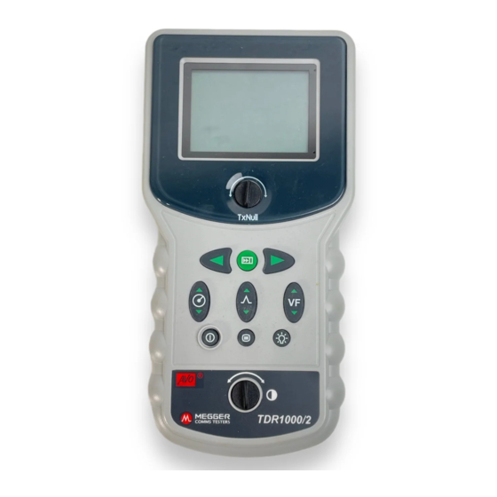
User controls and display The controls of the TDR have been arranged such that Instrument Display: The display shows the user the the instrument is easy to learn and use. The instrument c u r rent settings of the instrument and the re fle c t e d c o n t rols consist of the following e n e rgy trace from the cable connected. -
Página 8: Important
User controls and display Find key: Automatically moves the cursor to Menu: Allows the user to change the units of the first potential fault (change of impedance). measurement for Distance, Velocity Factor, Impedance and Test Rate. Refer to menu section later in this text. Power: Pressing this button will turn the instrument on or off depending on its current... - Página 9 Ensure that the whole length of the cable can be seen sockets of the instrument. on the display, and that the range selected is correct. Switch on the instrument. The TDR1000/2 will display Find key the start screen for a couple of seconds, followed by...
-
Página 10: Operation
Operation In the event of no reflections being visible, increase gain until any reflection can be easily identified. (If no reflections can be seen, try shorting or earthing the far end of the cable to ensure that you are “seeing” the whole length of the cable). The cursor can also be moved using the LEFT and RIGHT cursor keys. -
Página 11: Menu
The Menu key allows the user to change the units of keys. m e a s u rement Distance, Velocity factor, Impedance and Test Rate. By pressing the Menu key the TDR1000/2 will display: Distance Unit VF Format RATIO Impedance 75Ω... -
Página 12: Tx Null
Operation TX Null Velocity Factor Without the “TX Null” control, the transmitted pulse would The velocity factor is used by the instrument to be visible at the beginning of the trace, swamping any convert the measured time for a pulse to be reflected, re flections within the pulse length (the dead zone). -
Página 13: Pulse Widths
To improve on the accuracy of the measurement, Megger Limited repair agent. numerous techniques can be used, depending on the situation encountered. Not every situation can be Cleaning the instrument should only be done by wiping described, but the following points are effective and with a clean cloth dampened with soapy water or the most common and easily implemented methods. - Página 14 Operation Except where otherwise stated, this specification Output pulse: 5 volts peak to peak into open applies at an ambient temperature of 20C. circuit. Pulse widths determined by range and cable impedance: General 25Ω 50Ω 75Ω 100Ω Ranges: 10m, 30m, 100m, 300m, 1000m, 3000m (30ft, 100ft, 300ft, 1000ft, 3000ft, 10000ft) 20ns 20ns...
-
Página 15: Specifications
Specifications Backlight: Stays on for 1 minute when activated. Mechanical Batteries: Six LR6 (AA) type batteries, The instrument is designed for use indoors or Manganese-alkali or outdoors and is rated to IP54. nickel-cadmium or Case Dimensions: 230 mm long (9 inches) nickel-metal-hydride cells 115 mm wide (4.5 inches) Nominal voltage:... -
Página 16: Ordering Information
6420-125 Fused prod and clip set 6111-218 Miniature Clip Test Lead Set 6231-652 User Guide 6172-659 For use on energised systems rated up to 300V CATIII use the fused prod and clip set Megger Part Number 6111-218, must be used. -
Página 18: Guide De L'utilsateur
TDR1000/2 Time Domain Reflectometers Guide de l’utilsateur... -
Página 19: Avertissements De Securite
Pour l’utilisation sur des systèmes en service jusqu’à 300V, Installation de Catégorie III*, utiliser le jeu de pinces à fusible Megger réf. 6111-218. * Se rapporte aux surtensions transitoires que l’on risque de rencontrer dans les installations de câblage fixes. - Página 20 Sommaire Les symboles utilisés sur l’instrument sont: Avertissements de securite Introduction Attention : Se reporter aux notes qui Description générale l’accompagnent. Remplacement des piles Commandes utilisateur et affichage Equipement intégralement protégé par Disposition et fonctions une isolation doublée ou renforcée. Fonctionnement Flash de l’instrument testé...
- Página 21 M e rci d’avoir acheté le localisateur des défauts de l’impulsion réfléchie, et en le multipliant par la vitesse câbles TDR1000/2. Avant de tenter d’utiliser votre de la lumière et le facteur de vélocité, on peut établir nouvel instrument, veuillez pre n d re le temps de lire ce la distance réelle du point de réfle x i o n .
- Página 22 TDR1000/2 dispose d’un paramètre d’amplific a t i o n m i c roseconde. Le contraste de l’affichage est ajustable. En augmentant l’amplification, les petites e n t i è rement réglable pour compenser toutes les r é...
-
Página 23: Installation Et Remplacement Des Piles
Installation et remplacement des piles Quand le symbole piles déchargées apparaît dans la fenêtre d’affichage, les piles sont presque épuisées et devraient être remplacées le plus tôt possible. Utiliser seulement des piles alcalines IEC LR6 (AA) 1,5V ou des piles rechargeables 1,2V. Pour installer ou remplacer les piles, éteindre l’instrument. - Página 24 Commandes utilisateur et affichage Les commandes du TDR ont été disposées de telle Affichage de l’instrument: L’affichage montre à façon que l’instrument soit facile à apprendre et à l’utilisateur les réglages actuels de l’instrument et le u t i l i s e r. commandes l’instrument tracé...
- Página 25 Commandes utilisateur et affichage Curseur Dro i t e : Déplace le curseur de M a rc h e / A r r ê t : Appuyer sur ce bouton éteint ‘distance’ droite. répète ou allume l’instrument selon l’état dans lequel il automatiquement si on maintient la commande se tro u v e .
- Página 26 Mesure de la distance au défaut Allumer l’instrument. Le TDR1000/2 va aff i c h e r l’écran de départ pendant deux secondes, suivi d’un S’assurer que la longueur entière du câble peut être tracé.
- Página 27 Fonctionnement Si aucun défaut n’est évident, ajuster l’amplification Deux affichages de tracés typiques sont présentés jusqu’à ce que des réflexions majeures apparaissent. ci-dessous. Celui du haut montre un circuit ouvert à Les circuits ouverts et court-circuits devraient une distance de 2000m ; le second un court-circuit à aisément s’identifier.
- Página 28 Pour changer d’unités, utiliser les touches de curseur d’unités de mesure de Distance, de Facteur de GAUCHE ou DROITE. Vélocité, d’Impédance et de Cadence des Essais. En appuyant sur la touche Menu, le TDR1000/2 va afficher: Distance Unit VF Format...
- Página 29 Fonctionnement Tx Null Facteur de vélocité Sans le contrôle “TX Null”, l’impulsion transmise Le facteur de vélocité est utilisé par l’instrument pour serait visible au début du tracé, submergeant toute convertir le temps mesuré pour qu’une impulsion soit réflexion dans la longueur de l’impulsion (la zone réfléchie, en distance.
- Página 30 Fonctionnement une particularité du câble repose sur la justesse du sortie, se reporter aux données d’impulsions de facteur de vélocité. Toute erreur dans le facteur de sortie dans les Caractéristiques techniques du TDR à vélocité est directement liée aux erreurs de mesure la fin de ce guide.
- Página 31 En cas de panne, il devra être retourné à votre fournisseur ou à un réparateur agréé Megger Limited. Le nettoyage de l’instrument ne devra être effectué qu’en l’essuyant avec un chiffon propre humecté...
-
Página 32: Caractéristiques Techniques
Caractéristiques techniques Généralitiés Impulsion de sortie: Sauf prescription contraire, 5 Volts de pic à pic en circuit ouvert. caractéristiques techniques s’appliquent à Largeurs d’impulsions déterminées par la une température ambiante de 20C. portée et l’impédance du câble Allgemeines 25Ω 50Ω 75Ω... - Página 33 Caractéristiques techniques Coupure d’alimentation: Mécanique Automatique après 5 minutes sans appui L’instrument est conçu pour une utilisation sur une touche. en intérieur ou en extérieur et est étanche IP54. Rétro-éclairage: Reste allumé 1 minute une fois activé. Dimensions du boîtier: 230 mm de long (9 pouces) Piles: Six piles de type LR6 (AA), manganèse-...
-
Página 34: Informations De Commande
6 1 7 2 - 6 5 9 à bandoulière Jeu de cordons d’essais à pinces 6231-652 miniatures Guide de l’utilisateur 6172-659 Pour une utilisation sur des systèmes en service jusqu’à 300V CATIII, utiliser le jeu de sondes et pinces à fusible Megger réf. 6111-218. -
Página 36: Benutzerhandbuch
TDR1000/2 Time Domain Reflectometers Benutzerhandbuch... - Página 37 Sicherheit des Gerätes und der eigenen Person bei dem Benutzer. Für die Anwendung mit einem eingeschalteten System mit einer Einstufung von bis zu 300V, d.h. einer Installation der Kategorie III*, sollte der durch Sicherungen geschützte Klemmen-Satz Megger, Teilnummer 6111-218, angewendet werden.
- Página 38 Inhalt Sicherheitswarnungen Die auf diesem Instrument aufgeführten Symbole bedeuten: Einleitung Allgemeine Beschreibung Austausch der Batterien Vorsicht: Beziehen Sie sich auf die beiliegenden Hinweise. Benutzerkontrollen und Anzeigen Anordnung und Funktionen Gerät ist ganz durch doppelte oder Betrieb verstärkte Isolierung geschützt. Allgemeines Testverfahren Zeilenvorschub Instrument ist bis 3.7kV RMS Anschluss an ein zu testendes Kabel...
- Página 39 Einleitung Wir danken Ihnen für den Kauf des TDR1000/2 des Impulses und dem Empfang des reflektierten Kabelfehler-Detektors. Vor Anwendung Ihres neuen Impulses, und dem darauf folgenden Multiplizieren Gerätes sollten Sie sich die Zeit nehmen, dieses dieses Wertes mit der Lichtgeschwindigkeit und dem Benutzerhandbuch sorgfältig durchzulesen, da Ihnen...
-
Página 40: Einleitung
Grenze, d.h. wie weit Sie der Cursor auf das Ende des Kabels gelegt, und der sehen können. Das TDR1000/2 verfügt über eine Geschwindigkeitsfaktor auf dem TDR so eingestellt e i n s t e l l b a re Gewinnstellung, um das Aufspüren von w e rden, dass die korrekte Kabellänge angezeigt wird . - Página 41 Einlegen und austausches der batterien Wenn das Batterie-Symbol im Anzeigefenster erscheint, sind die Zellen beinahe leer, und sollten so bald wie möglich ausgetauscht werden. Sie sollten dabei entweder nur IEC LR6 (AA) 1,5V Alkalizellen oder nur aufladbare 1,2V Zellen verwenden. Um Zellen einzulegen oder auszutauschen, sollten Sie zuerst das Instrument abschalten.
- Página 42 Benutzerkontrollen und Anzeigen Die Kontrollen des TDR wurden auf eine solche We i s e I n s t r u m e n t a n z e i g e : Die Anzeige zeigt dem Benutzer angebracht, dass Instrument einfach die aktuelle Einstellung des Instrumentes und die...
-
Página 43: Benutzerkontrollen Und Anzeigen
Benutzerkontrollen und Anzeigen Cursor rechts: Bewegt den ‘Abstands-’Cursor S t ro m a n s c h l u s s : Drücken dieses nach rechts. Wenn die Taste herunterg e h a l t e n Schalters wird das Instrument je nach seinem w i rd, wird diese Funktion automatisch wiederholt. - Página 44 Zusammenhang auf den Abschnitt für Optionen. Buchsen des Instrumentes eingesteckt sind. Wenn Sie eine Kabelimpedanz von 25 wählen, wird Schalten Sie das Instrument an. Das TDR1000/2 wird automatisch ein interner 50Hz/60Hz Filter eingeschaltet. zuerst zwei Sekunden lang die Startsequenz anzeigen, die dann von einer Spuranzeige gefolgt wird.
-
Página 45: Betrieb
Betrieb Änderungen Kabelimpedanz können leicht HINWEIS: Die Abstandsberechnung wird mit Hilfe des in übersehen werden, wenn der Gewinn auf ein Minimum das TDR eingegebenen Geschwindigkeitsfaktors gestellt ist. Das Erhöhen des Gewinns gestaltet den d u rchgeführt. Wenn dieser Geschwindigkeitsfaktor für Fehler sichtbare r. -
Página 46: Menü
Die M e n ü- Taste ermöglicht dem Benutzer das Ändern LINKS oder RECHTS. der Messeinheiten für Abstand, Geschwindigkeitsfaktor, Impedanz und Te s t r a t e . Das Drücken der M e n ü -Taste ruft die folgenden TDR1000/2-Anzeige ab: Distance Unit VF Format RATIO Impedance 75Ω... -
Página 47: Tx-Null
Betrieb T X - N u l l Ohne die “TX-Null” Kontrolle würde der übertragene Impuls am Anfang der Spur sichtbar werden, und d a d u rch mögliche Reflektionen innerhalb Impulslänge überschreiben (der toten Zone). Der ‘TX- N u l l ’ - K reis gleicht der charakteristischen Impedanz des getesteten Kabels und produziert einen gleichartigen Impuls. - Página 48 Betrieb • Die Genauigkeit des “Abstandes bis zum Fehler” wird Suchen Sie den Anfang dieser Reflektion mit Hilfe jedoch nicht von der Länge des Impulses beeinflu s s t . des Ve r f a h rens, das im Abschnitt ‘Betrieb’ dieses Trotz dieser Tatsache kann bei zwei oder mehre ren eng Handbuches beschrieben ist.
-
Página 49: Pflege Und Wartung
über keinerlei wartungsfähige Teile. Im Falle eines Ausfalls sollte es daher an ihren Lieferanten oder eine o ffizielle Megger Limited R e p a r a t u r a g e n t u r zurückgeschickt werd e n . -
Página 50: Spezifikation
Spezifikation Ausser wenn es anders angegeben ist, trifft diese K reis. Impulsbreiten werden durc h S p e z i fikation bei einer Umgebungstemperatur von 20C B e reich und Kabelimpedanz bestimmt: z u . 5 0 Ω 7 5 Ω 1 0 0 Ω... - Página 51 Spezifikation A b s c h a l t u n g : E M V: Automatisch nach 5 Minuten, innerhalb Erfüllt Vorschriften welcher keine Tasten gedrückt werd e n . E l e k t ro m a g n e t i s c h e n Ve r t r ä...
- Página 52 Spezifikation K a b e l l ä n g e : 2 Meter lang, bestehend aus 2 x 4mm ummantelten Anschlüssen mit Mini- K ro k o d i l k l e m m e n A n z e i g e : 128 64 pixel Graphics LCD.
- Página 53 Test- & Tragekoffer mit Riemen 6420-125 Sonde und Klemme, Satz mit Sicherung Testkabel mit Mini-Klemmen , Satz 6231-652 6111-218 Benutzerhandbuch 6172-659 Für Anschluss an eingeschaltete Systeme bis zu 300V KAT III sollte der mit Sicherungen geschützte Sonden- und Klemmensatz, Megger Teilnummer 6111-218, angewendet werden.
- Página 54 TDR1000/2 Time Domain Reflectometers Guía del Usuario...
-
Página 55: Avisos De Seguridad
En sistemas activos con Instalación Categoría III* de hasta 300V deberá utilizarse el conjunto de pinza con fusible pieza Megger número 6111-218. * Se refiere a los sobrevoltajes momentáneos que posiblemente surjan en las instalaciones de cableado fijo. - Página 56 Indice de materias Símbolos usados en el instrumento: Avios de seguridad Introducción Precaución: Consulte las notas adjuntas. Descripción general Recambio de baterías Equipo totalmente protegido mediante Visualizador y controles del usuario aislamiento doble o reforzado. Disposición y funciones El aislamiento del instrumento ha sido Funcionamiento probado a 3,7kV RMS.
-
Página 57: Introducción
Gracias por haber comprado el localizador de fallos distancia efectiva hasta el punto de reflexión. de cable TDR1000/2. Antes de intentar usar su nuevo Las reflexiones son causadas por cambios en la instrumento rogamos lea esta guía del usuario, ya impedancia característica de los cables, tales como... - Página 58 Una luz posterior facilita la lectura en condiciones de alumbrado El TDR1000/2 puede ser utilizado en cualquier cable ambiental reducido. que conste por lo menos de dos elementos metálicos aislados, uno de los cuales puede ser el blindaje o El instrumento puede funcionar con baterías de...
-
Página 59: Instalación Y Recambio De Baterías
Instalación y recambio de baterías Cuando aparece el símbolo de bajo nivel de batería las pilas están casi agotadas y deberán recambiarse lo antes posible. Use pilas alcalinas IEC LR6 (AA) 1,5V o pilas de 1,2V recargables solamente. Para instalar o recambiar las pilas, apague el instrumento, desconecte los conductores de prueba, afloje los tornillos de sujeción de la tapa de la batería y desmonte la tapa. -
Página 60: Visualizador Y Controles Del Usuario
Visualizador y controles del usuario Los controles del TDR se han dispuesto para facilitar Visualizador del instrumento: El visualizador la lectura y el manejo del instrumento. He aquí los muestra al usuario los ajustes actuales del controles del instrumento: instrumento y el trazo de energía reflejado del cable conectado. - Página 61 Visualizador y controles del usuario Cursor dere c h o : Mueve el cursor de ‘distancia’ Encendido / Apagado: Al pulsar este botón se a la derecha. El movimiento se re p i t e enciende o apaga el instrumento, dependiendo automáticamente si se mantiene pulsado.
-
Página 62: Funcionamiento
firmemente insertados en las conmuta automáticamente un filtro interno de tomas del instrumento. 50Hz/60Hz. Encienda el instrumento. El TDR1000/2 visualizará Medición de la distancia hasta el fallo pantalla de inicio durante un par de segundos, Asegure que la longitud completa del cable aparezca seguido de un trazo. - Página 63 Funcionamiento Si no hay fallos evidentes, ajuste la ganancia hasta que A continuación se ilustran dos visualizaciones de trazo aparezcan algunas reflexiones importantes. Los típicas. La superior muestra un circuito abierto a 2000m circuitos abiertos y cortocircuitos deberán ser de distancia, mientras que la segunda muestra un i d e n t i ficados con facilidad.
- Página 64 Para cambiar las unidades use las teclas IZQUIERDA velocidad, impedancia y ritmo de prueba. o DERECHA del cursor. Pulsando la tecla Menú el TDR1000/2 visualizará: Distance Unit VF Format RATIO Impedance 75Ω...
- Página 65 Funcionamiento Tx Null Factor de velocidad Sin el control “TX Null”, el impulso transmitido sería El factor de velocidad es usado por el instrumento visible al iniciarse el trazo, anegando todas las para convertir en una distancia el tiempo medido reflexiones ocurridas dentro de la longitud del para un impulso que ha de ser reflejado.
- Página 66 Funcionamiento La medición de la distancia al fallo podrá hacerse impulso que puede ver ambas características. ahora con más confianza. La capacidad del Para características de impulso de salida, vea los instrumento para medir con precisión la distancia datos de impulso de salida en las especificaciones hasta una característica de cable determinada del TDR al final de esta guía.
- Página 67 Cuidado y mantenimiento Aparte del recambio de las baterías, el instrumento no incorpora piezas que requieran servicio. En caso de fallo, el instrumento deberá devolverse al p roveedor agencia reparación Megger Limited aprobada.
-
Página 68: Técnicas Para Mejorar La Precisión
Técnicas para mejorar la precisión Para limpiar el instrumento solamente se requiere un Impulso de salida: 5 voltios de pico a pico en trapo limpio humedecido en agua jabonosa o en circuito abierto. Anchos de impulso determinados alcohol isopropílico (IPA). por el alcance y la impedancia del cable: Generales Salvo donde se indique de otro modo, estas... -
Página 69: Especificaciones
Especificaciones Ritmo de regeneración: activados de hasta 300V CAT III ***Fase a tierra (415 V fase a fase). Deberán Seleccionable desde el menú. utilizarse conductores provistos de Una vez por segundo o tres fusibles, si el voltaje entre los bornes es veces por segundo. - Página 70 Especificaciones Conectores: Dos bornes de seguridad de 4mm. Conductor de prueba: 2 metros de largo que comprenden 2conectores a pinzas cocodrilo blindados en miniatura de 4mm. Visualizador: LCD de gráficos de 128 64 pixeles. Medioambientales Temperatura de trabajo: -15C a +50C (5F a 122F) Temperatura de almacenaje: - 20C a 70C (-4F a 158F)
-
Página 71: Información De Pedido
Juego de pinza y punta y fusible 6111-218 con correa Juego de conductor de prueba con 6231-652 pinza miniatura Guía del usuario 6172-659 Para sistemas energizados con capacidad de hasta 300V CATIII, deberá utilizarse el conjunto de pinza y punta con fusible pieza Megger número 6111-218. - Página 72 TDR1000/2 Time Domain Reflectometers Guida per l’utente...
- Página 73 AVVERTENZE DI ANTINFORTUNISTICA Anche se il tester non genera tensioni pericolose, i circuiti a cui è collegato possono provocare scosse elettriche o la for azione di archi (provocata da cortocircuiti). Anche se questi pericoli sono stati presi in considerazione in fase di fabbricazione, l’utente deve considerare questi rischi in quanto responsabile della sua incolumità.
- Página 74 Indice I simboli stampigliati sullo strumento Avvertenze di Antinfortunistica sono i seguenti:: Prefazione Generalità Avvertenza: Leggere le note riportate Sostituzione della batteria sotto il simbolo. Comandi e display L’apparecchio è interamente rivestito di Layout e funzioni doppio isolamento isolamento rinforzato. Uso dello strumento Verifiche preliminari Collegamento al cavo durante il test...
- Página 75 TDR1000/2. Prima di utilizzare lo strumento per Le riflessioni sono provocate dalle variazioni la prima volta, leggere attentamente il manuale d’uso, dell’impedenza dei cavi, dovute a loro volta a che riporta informazioni importanti destinate ad giunzioni imperfette o a discontinuità...
- Página 76 La presenza di una luce sul re t ro del cavo. Il TDR1000/2 è dotato di reti intern e d e l l ’ a p p a recchio agevola la visualizzazione del corrispondenti che consentono di testare cavi da 25 , display quando la visibilità...
- Página 77 Montaggio e sostituzione delle batterie La comparsa del simbolo scarica imminente della batteria nella finestra del display indica che gli elementi della batteria stanno per scaricarsi e che la batteria va sostituita al più presto. Utilizzare esclusivamente batterie elementi alcaline ricaricabili IEC LR6 (stilo - AA) da 1,5V o da 1,2V.
- Página 78 Comandi e simboli sul display I comandi del TDR sono stati disposti sullo strumento Display strumento: Il display visualizza i valori al fine di agevolarne la lettura e la facilità di utilizzo. I attualmente impostati sullo strumento e il tracciato comandi dello strumento sono indicati qui di seguito: dell’energia riflessa dal cavo collegato.
- Página 79 Comandi e simboli sul display C u r s o re destro : Sposta verso destra il Accensione: Premere questo pulsante per cursore ‘distanza’. L’operazione viene ripetuta accendere o spegnere lo strumento. se si tiene premuto il tasto. Menu: Consente all’utente di cambiare le Tasto Cerca: Sposta automaticamente il unità...
-
Página 80: Uso Dello Strumento
50 Hz/60 Hz. inseriti nello strumento. Misurazione della distanza dal guasto Accendere lo strumento. Il TDR1000/2 presenta sul display la schermata introduttiva per un paio di Verificare che l’intero cavo sia visibile sul display e secondi, poi visualizza un tracciato. Lo strumento che la portata prescelta sia corretta. - Página 81 Uso dello strumento Qualora non si individuino guasti, re g o l a re il Qualora questo fattore velocità non sia corretto per io guadagno fino a quando appaiono sul display circuito da sottoporre a test, la distanza visualizzata riflessioni di una certa entità. L’individuazione di risulterà...
- Página 82 Per cambiare le unità, agire sui tasti cursore di misura per la Distanza, il Fattore velocità, SINISTRO o DESTRO. l’Impedenza e la Frequenza test. P remendo il tasto M e n u, appare la seguente schermata sul TDR1000/2: Distance Unit VF Format RATIO Impedance 75Ω...
- Página 83 Uso dello strumento Ann. trasm. Senza il comando “Ann. trasm.”, l’impulso trasmesso s a rebbe visibile all’inizio del tracciato ed oscure re b b e eventuali riflessioni presenti sull’impulso (la”zona morta”). Il circuito ‘Ann. trasm.’ è caratterizzato dalla medesima impedenza del cavo sottoposto a test per cre a re un impulso equivalente.
- Página 84 Uso dello strumento • correlata alla lunghezza dell’impulso. In presenza Individuare l’inizio della riflessione osservando le però di due o più guasti vicini (esclusi i circuiti aperti istruzioni riportate nella sezione Uso dello strumento. e i cortocircuiti), i guasti dal secondo in poi possono •...
- Página 85 è dotato di parti sostituibili dall’utente. In caso di guasto, lo strumento va rispedito al fornitore o ad un c e n t ro di assistenza tecnica Megger Limited approvato. Pulire lo strumento con un panno inumidito in acqua...
-
Página 86: Dati Tecnici
Dati tecnici Salvo diverse indicazioni, i dati tecnici indicati qui di Impulso erogato: 5 volt tra i valori massimi nel seguito si riferiscono alla temperatura ambiente di c i rcuito aperto. Le ampiezze degli impulsi sono 20C. determinate dalla portata e dall’impedenza del cavo: Generalità... - Página 87 Dati tecnici Spegnimento: Automatico dopo 5 minuti Componenti meccanici dall’ultima volta che si era premuto Lo strumento può essere usato sia al chiuso che un tasto. all’aperto, con grado di protezione IP54. I l l u m i n a z i o n e : Rimane accesa per 1 minuto una Dimensioni involucro : volta attivata.
- Página 88 Set puntale e clip con fusibile 6111-218 Set di cavi con pinzetta 6231-652 miniaturizzata Manuale d’uso 6172-659 L’impiego dello strumento su impianti sotto tensione fino a 300V CAT III prevede l’utilizzo del set puntale e clip con fusibile Megger codice 6111-218.
- Página 90 TDR1000/2 Time Domain Reflectometers Användarmanual...
- Página 91 Vid användning på spänningssatta system med märkspänning upp till 300 V Installationer av Kategori III*, så måste den avsäkrade klämsatsen Megger med artikelnummer 6111-218 användas. * Syftar på de transienta överspänningar som kan tänkas uppstå i fasta elinstallationer.
- Página 92 Innehåll Följande symboler finns angivna på instrumentet: Säkerhetsföreskrifter Inledning Försiktighet: Se kompletterande Allmän beskrivning upplysningar. Batteribyte Utrustningen i sin helhet är skyddad med Användarkontroller och display dubbel eller förstärkt isolering. Layout och funktioner Användning Instrumentet överslagstestat till 3,7 kV rms. Generell testrutin Ansluta till testad kabel (C.U.T) Utrustningen...
- Página 93 Inledning Tack för att du köpt TDR1000/2 kabelfelsdetektor. Reflektioner orsakas av ändringar i kabelns Innan du börjar använda det nya instrumentet, karakteristiska impedans, som t.ex. dåliga skarvar rekommenderar vi att du tar dig tid att läsa denna eller diskontinuiteter. Fel som uppvisar en impedans bruksanvisning.
-
Página 94: Inledning
Genom att öka förstärkningen blir svaga reflektioner bakgrundsbelysning underlättar avläsning när det tydligare. omgivande ljuset är svagt. TDR1000/2 kan användas på varje kabel som består Instrumentet kan strömförsörjas med batterier av av minst två metalliska element, varav det ena kan typen mangan-akali, nickel-kadmium eller nickel- vara kabelns hölje eller skärm. -
Página 95: Batteribyte
Batteribyte När batterisymbolen visas på displayen är batterierna nästan förbrukade och bör bytas så snart som möjligt. Använd bara alkalibatterier av typen IEC LR6 (AA) på 1,5V eller 1,2V laddningsbara batterier. Vid insättning eller byte av batterier, stäng först av instrumentet. -
Página 96: Användarkontroller Och Display
Användarkontroller och display K o n t ro l l e rna på TDR har arrangerats så att Instrumentdisplay: Displayen visar användaren de instrumentet ska vara lätt att lära sig och använda. aktuella inställningarna av instrumentet och det Instrumentkontrollerna utgörs av följande: reflekterade energisvepet (kurvan) från den anslutna kabeln. - Página 97 Användarkontroller och display Markör höger: Flyttar ”distansmarkören” åt På/Av: Ett tryck på knappen slår på eller höger. Automatisk upprepning fås om den stänger av instrumentet, beroende på dess hålls intryckt. aktuella tillstånd. Sök-tangent: Flyttar automatiskt markören Meny: Låter användaren ändra mätenheterna till första potentiella...
- Página 98 Kontrollera att testkablarna är ordentligt anslutna till Säkerställ att kabeln kan ses på displayen i hela sin instrumentets kontakter. längd, och att rätt område har valts. Slå på instrumentet. TDR1000/2 kommer först att Sök-tangenten visa startskärmen under några sekunder, åtföljt av ett Sök-tangenten söker efter den längst bort...
-
Página 99: Användning
Användning pulsen för varje potentiellt ”nära änden”-fel (se avsnittet om Tx Null). händelse inga reflektioner syns, öka förstärkningen tills varje reflektion kan ses tydligt. (Om inga reflektioner kan ses, försök då med att kortsluta eller jorda kabelns bortre ände för att säkerställa att du ”ser”... -
Página 100: Meny
ä t e n h e t e rna för avstånd, hastighetsfaktor (VF), För att ändra enheterna, använd markörtangenterna impedans och testfrekvens. VÄNSTER och HÖGER. Vid tryck på M e n y-tangenten visar TDR1000/2 följande: Distance Unit VF Format... -
Página 101: Tx Null
Användning Tx Null Utan ”Tx Null”-kontrollen skulle den utsända pulsen vara synlig i början av svepet, och dränka alla reflektioner inom pulsens längd (dödzonen). ”Tx N u l l ” - k retsen matchar mätta kabelns karakteristiska impedans för att därigenom skapa en ekvivalent puls. - Página 102 Användning • nästa egenskap delvis skymmas av reflektionen från Lokalisera början på denna reflektion enligt det första felet. Därför bör instrumentet, för beskrivningen i avsnittet Användning i denna potentiella multipla fel, användas med kortast möjliga bruksanvisning. mätområde, och kortast möjliga pulsbredd, som kan •...
-
Página 103: Skötsel Och Underhåll
ä n d a ren. I händelse av fel bör instrumentet re t u rneras till återförsäljaren eller en godkänd serviceverkstad för Megger Limited. Rengöring av instrumentet böra bara göras genom att torka det med en ren trasa fuktad med såpvatten... -
Página 104: Specifikation
Specifikation Om inte annat anges gäller denna specifikation vid en Utsänd puls: 5 volt ”peak-to-peak” (topp-till-topp) till omgivningstemperatur på 20C. öppen krets. Pulsbredderna bestäms av mätområde och kabelimpedans: Allmänt 25Ω 50Ω 75Ω 100Ω Områden: 10m, 30m, 100m, 300m, 1000m, 3000m (30ft, 100ft, 300ft, 1000ft, 3000ft, 10000ft) 20ns 20ns... - Página 105 Specifikation Avstängning: Compatibility Specifications (Lätt Sker automatiskt efter 5 minuter utan industri) BS EN 61326-1, med någon tangenttryckning. minimumprestanda ’B’ för alla okänslighetstester. Bakgrundsbelysning: Påslagen i 1 minut efter aktivering. Mekaniskt Instrumentet är konstruerat för användning inom- eller utomhus och har Batterier: batterier typen...
- Página 106 Test- & bärväska med rem 6420-125 Avsäkrad spets- och klämsats 6111-218 Sats med miniatyrklämm 6231-652 a och testsladdar Bruksanvisning 6172-659 För användning på spänningssatta system med märkspänning upp till 300V CAT III, måste den avsäkrade spets- och klämsatsen Megger, artikelnummer 6111-218, användas.
- Página 107 Notes...
- Página 108 Notes...
- Página 109 Notes...
- Página 110 This instrument is manufactured in the United Kingdom. The company reserves the right to change the specification or design without prior notice. Megger is a re g i s t e red trademark Part No. 6172-659 V03 Printed in England 10HH...