Tripp-Lite APS 612 PowerVerter Manual De Operación
Ocultar thumbs
Ver también para APS 612 PowerVerter:
- Manual del propietário (24 páginas) ,
- El manual del propietario (24 páginas)
Tabla de contenido
Publicidad
Idiomas disponibles
Idiomas disponibles
Enlaces rápidos
Owner's Manual
APS 612 PowerVerter
• Voltage- and Frequency-Controlled • Peak Power • High Efficiency
Copyright © 2002 Tripp Lite. PowerVerter
Inverter/Charger (120V, 60 Hz)
1111 W. 35th Street Chicago, IL 60609 USA
Customer Support: (773) 869-1234 • www.tripplite.com
®
is a registered trademark of Tripp Lite. All rights reserved.
®
2
4
5
9
11
11
12
13
14
Publicidad
Capítulos
Tabla de contenido
Solución de problemas

Manuales relacionados para Tripp-Lite APS 612 PowerVerter


Resumen de contenidos para Tripp-Lite APS 612 PowerVerter
-
Página 1: Tabla De Contenido
Owner’s Manual APS 612 PowerVerter ® Inverter/Charger (120V, 60 Hz) • Voltage- and Frequency-Controlled • Peak Power • High Efficiency Introduction Important Safety Instructions Configuration & Connection Features Maintenance and Service Warranty Troubleshooting Specifications Español 1111 W. 35th Street Chicago, IL 60609 USA Customer Support: (773) 869-1234 •... -
Página 2: Introduction
Introduction Congratulations! You’ve purchased the most advanced, feature-rich integrated inverter/charger on the market. Your APS powers connected equipment, switching manually or automatically from utility power to power inverted from an external battery or batteries. In addition to reliable APS performance, your model provides: High Efficiency Output Your APS’s advanced circuitry produces a more efficient DC-to-AC conversion, minimizing energy loss.This allows you to run connected equipment longer between battery charges. - Página 3 Introduction continued 3-Stage Battery Charger Your APS recharges your battery faster than Stage 2 conventional chargers because its three-stage Absorption charger profile (Bulk,Absorption and Float) is optimized for the type of battery you use (Wet or Gel).* In addition, the advanced Stage 3 charging system protects against over-charge Float...
-
Página 4: Important Safety Instructions
Important Safety Instructions SAVE THESE INSTRUCTIONS T T h h i i s s m m a a n n u u a a l l c c o o n n t t a a i i n n s s i i m m p p o o r r t t a a n n t t i i n n s s t t r r u u c c t t i i o o n n s s a a n n d d w w a a r r n n i i n n g g s s t t h h a a t t s s h h o o u u l l d d b b e e f f o o l l l l o o w w e e d d d d u u r r i i n n g g t t h h e e i i n n s s t t a a l l l l a a t t i i o o n n , , o o p p e e r r a a t t i i o o n n a a n n d d s s t t o o r r a a g g e e o o f f a a l l l l T T r r i i p p p p L L i i t t e e A A P P S S S S y y s s t t e e m m s s . -
Página 5: Configuration & Connection
Configuration DIP Switches Using a small tool, set the four “Battery Type / Voltage Point” Configuration DIP Switches (located on the front panel of your APS); see Diagram 4, p. 28. • Select Battery Type (DIP Switch #1) CAUTION:The Battery Type DIP Switch setting must match the type of batteries you connect or your batteries may be degraded or damaged over an extended period of time. -
Página 6: Battery Selection
Battery Selection Selecting Battery Type Select a battery or system of batteries that will provide your APS with proper DC voltage and an adequate amp hour capacity.* Select ‘Deep-Cycle’ batteries to enjoy optimum performance from your APS. Batteries of either Wet-Cell (vented) or Gel-Cell/Absorbed Glass Mat (sealed) construction are ideal. -
Página 7: Battery Connection
Battery Connection 1. Make sure that your APS batteries have proper overcurrent protection. NEC article 551 requires that you install a recognized UL component fuse block and UL listed fuse within 18 inches of the battery. The fuse’s rating must equal or exceed the Minimum DC Fuse Rating listed in your APS model’s specifications on page 13. - Página 8 AC Connection Before AC connection, match the power requirements of your equipment with the power output of your APS to avoid overload. When figuring the power requirements of your equipment, do not confuse “continuous” power ratings with “peak” power ratings. Electric motors require more power to turn on (“peak power”) than they require to run continuously.“Peak”...
-
Página 9: Features
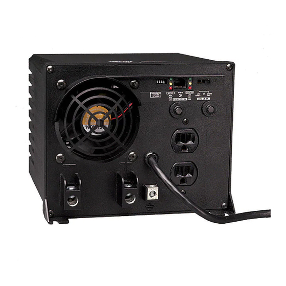
Switches, Indicator Lights & Other Features (See Diagram 4, p. 28, to locate the following switches, indicator lights and other features.) Switches 1 1 . . O O p p e e r r a a t t i i n n g g M M o o d d e e S S w w i i t t c c h h : : This switch selects the APS operating mode (either “AUTO/REMOTE”, “OFF”... - Página 10 Switches, Indicator Lights & Other Features continued Other Features 7 7 . . D D C C P P o o w w e e r r T T e e r r m m i i n n a a l l s s : : These terminals should be wired to your battery terminals. See “Battery Connection”, p.
-
Página 11: Maintenance And Service
Maintenance & Service Maintenance Your APS model requires no maintenance but should be kept dry at all times. Periodically check all connections both at the unit and at the battery. Clean and tighten connections as necessary. Service If returning your APS to Tripp Lite,please pack the APS carefully,using the ORIGINAL PACKING MATERIAL that came with the unit. -
Página 12: Troubleshooting
Troubleshooting Try these remedies for common APS problems before calling for help. Call Tripp Lite Customer Service at (773) 869-1234 before returning your APS for service. SYMPTOM PROBLEMS CORRECTIONS APS does not provide APS not properly connected to Connect APS to utility power. AC output (AC input present) utility power. -
Página 13: Specifications
Specifications MODEL: APS612 SERIES: AGAP60012MVJ Weight: 38.0 lbs. INVERTER Continuous power (@ 20° C): 600 W Surge power: 1200 W Efficiency (Full Load): Minimum/Maximum DC Fuse Rating: 100A/200A DC Input Current @ Nominal V DC Full Load 56 A Nominal Input Volts: 12 VDC DC Input Voltage Range: 10-15 VDC... -
Página 14: Español
Manual de Operación APS 612 PowerVerter ® Inversores / Cargadores de Energía (120V, 60 Hz) • Con Voltaje y Frecuencia Controlada • Energía de Cresta • Alta Eficiencia Introducción Seguridad Configuración y Conexión Características Mantenimiento y Servicio Garantía Resolución de Problemas... -
Página 15: Introducción
Introducción ¡Felicitaciones! Usted ha adquirido el inversor / cargador de batería integrado más avanzado y con más características en el mercado. Este modelo APS suministrará a sus equipos energía de CA mientras ésta esté presente. Durante un apagón, caída o subida de voltaje, esta unidad cambia automáticamente a la batería externa para suministrar energía de CA de voltaje y frecuencia controlada. -
Página 16: Tarjetas De Circuitos Protegidas
Introducción continua Cargador Avanzado de 3 Etapas para Baterías Etapa 2 Este sistema APS recargará sus baterías más Absorción rápido que otros cargadores convencionales debido a que su perfil de recarga de 3 etapas (Alimentación Masa, Absorción Etapa 3 Allmentación Alimentación por Flotador) provee óptimo por Flotador rendimiento independientemente del tipo de... -
Página 17: Seguridad
Seguridad GUARDE ESTAS INSTRUCCIONES E E s s t t e e m m a a n n u u a a l l c c o o n n t t i i e e n n e e a a d d v v e e r r t t e e n n c c i i a a s s e e i i n n s s t t r r u u c c c c i i o o n n e e s s i i m m p p o o r r t t a a n n t t e e s s q q u u e e d d e e b b e e n n s s e e g g u u i i r r s s e e d d u u r r a a n n t t e e l l a a i i n n s s t t a a l l a a c c i i ó... -
Página 18: Interruptores Dip
Configuración Interruptores DIP Usando una herramienta pequeña, ajuste los 4 Interruptores DIP de Configuración, Grupo A: “Battery Type / Voltage Point” (tipo de baterías / punto de voltaje) ubicados en el panel frontal del sistema APS (vea el Diagrama 4, página 28) para seleccionar el tipo de baterías que desea utilizar y programar el rango de voltaje para el cambio automático del sistema APS a energía de batería. -
Página 19: Selección De Baterías
Selección de Baterías Seleccione el Tipo de Batería(s) Seleccione una batería o sistema de baterías que suministre voltaje apropiado de CD y capacidad adecuada en amperios / hora al sistema APS.* Seleccione baterías de ciclo profundo para obtener el máximo rendimiento de su sistema APS. Las baterías húmedas (ventiladas) o de gel / fibra de vidrio absorbido (selladas) son ideales. -
Página 20: Conexión De Baterías
Conexión de Baterías 1. Confirme que las baterías del APS cuenten con adecuada protección para sobrecargas de corriente. El artículo NEC 551 requiere que usted instale un bloque de fusibles de componente UL reconocido y un fusible UL listado a 18 pulgadas de la batería. La capacidad en amperios del fusible debe ser igual o superior a la capacidad mínima de amperios de CC del fusible que se muestra en la ficha técnica del modelo del APS en la página 26. -
Página 21: Conexión De La Entrada Eléctrica De Ca
Conexión de CA Antes de la conexión de CA, cerciórese de que la demanda de energía de sus equipos coincida con la capacidad de salida del APS para evitar sobrecargas. Cuando calcule la demanda de energía de sus equipos, no confunda el índice de energía “continua”... -
Página 22: Características
Interruptores, Luces Indicadoras y Otras Características (Vea el Díagrama 4 en la página 28 para localizar los siguientes interruptores, luces indicadoras y otras características.) Interruptores 1 1 . . I I n n t t e e r r r r u u p p t t o o r r “ “ O O p p e e r r a a t t i i n n g g M M o o d d e e ” ” ( ( M M o o d d o o d d e e o o p p e e r r a a c c i i ó ó n n ) ) : : Este interruptor selecciona el modo de operación del sistema APS: “AUTO/REMOTE”... -
Página 23: Otras Características
Interruptores, Luces Indicadoras y Otras Características continua 6 6 . . “ “ B B A A T T T T E E R R Y Y H H I I / / M M E E D D / / L L O O ” ” ( ( B B A A T T E E R R Í Í A A H H I I / / M M E E D D / / L L O O ) ) : : Estas tres luces se encenderán en varias secuencias para mostrar el nivel de carga y el voltaje aproximados del banco de baterías conectado y advertirle sobre varias fallas: INDICACIÓN DE LA CARGA DE LA BATERÍA (Aproximado) -
Página 24: Mantenimiento Y Servicio
Mantenimiento y Servicio Mantenimiento Este sistema APS no requiere mantenimiento alguno. No obstante, debe mantenerse seco en todo momento.Verifique periódicamente todas las conexiones y cables en la unidad y sus baterías. Apriete y limpie estas conexiones como sea necesario. Servicio Si necesita enviar el sistema APS a Tripp Lite, por favor empáquelo cuidadosamente usando el MATERIAL ORIGINAL DE EMPAQUE.Adjunte una carta con la descripción de los síntomas del problema. -
Página 25: Resolución De Problemas
Resolucion de Problemas Si experimenta problemas comunes refiérase a esta guía antes de llamar al centro de servicios. Llame al Servicios a Clientes de Tripp Lite antes de enviar el sistema APS. SIMTOMA PROBLEMAS SOLUCION El sistema APS no suministra APS no connecta correctamente Conecte el sistema APS a una toma salida de CA (energía de CA... -
Página 26: Especificaciones
Especificaciones MODELO: APS612 SERIO: AGAP60012MVJ Peso: 11.9 Kg INVERSOR Energía continua a 20º C 600 Vatios Energía de sobretensiones transitorias: 1200 Vatios Eficiencia (Carga Completa): Indice Mínimo/Maximo de Capacidad del Fusible: 100A/200A Corriente de Entrada de CD a Niveles Nominales Carga Completa: 56 A Voltios Nominales de Entrada:... - Página 27 Diagrams/Esquemas X Volts See Battery Connection, Pg. 7. 1.1 is the fuse. X = Your APS’s Inverter's Nominal Input Voltage. (See specs.) Refiérase a la sección Conexión de baterías, Pág. 20. 1.1 representa el fusible. X = Voltaje nominal de entrada del inversor del APS.
- Página 28 Diagrams/Esquemas 1. Operating Mode Switch 1. Interruptor “Operating Mode” (Modo de operación) 2. DIP Switches 2. Interruptores DIP 3. “LINE” 3. “LINE” (Línea) 4. “INV” (Inverting) 4. “INV” (Inversor) 5. “LOAD” 5. “LOAD” (Carga Conectada) 6. “BATTERY HI/MED/LO” 6. “BATTERY HI/MED/LO” (Carga de 7.