Tabla de contenido
Publicidad
Idiomas disponibles
Idiomas disponibles
Enlaces rápidos
P.O. Box 342, Delavan, WI 53115
Phone: 1-800-365-6832 • Fax: 1-800-526-3757
E-Mail: info@flotecwater.com • Web Site: http://www.flotecpump.com
READ AND FOLLOW
SAFETY INSTRUCTIONS!
This is the safety alert symbol. When you see this sym-
bol on your pump or in this manual, look for one of the
following signal words and be alert to the potential for per-
sonal injury.
warns about hazards that will cause serious
personal injury, death or major property damage if ignored.
warns about hazards that can cause serious
personal injury, death or major property damage if ignored.
warns about hazards that will or can cause
minor personal injury or property damage if ignored.
The label NOTICE indicates special instructions which are
important but not related to hazards.
Carefully read and follow all safety instructions in this
manual.
Check your local codes before installing. You must comply
with their rules.
Vent sewage or septic tank according to local codes.
Do not install the basin or pump in any location classified as
hazardous by the United States National Electrical Code (NEC),
or by the Canadian Electrical Code (CEC), where applicable.
DESCRIPTION
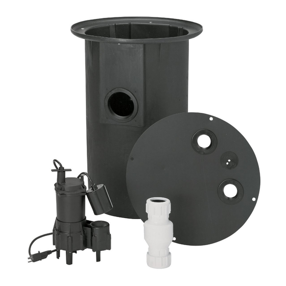
FLOTEC Sewage Pump System, Model Number FP400C, is
ideal for basement installations, pumping below-grade toilets,
and laundry facilities. It includes a lightweight, corrosion resis-
tant sump/sewage basin, FPW73-15 and cover, FPW73-17P.
These basins are used for residential, commercial, and indus-
trial collection of sewage, effluent drainage and seepage
water. The basin cover kit includes an inlet hub, a gas tight
cover, vent and discharge grommets, cord seals, gaskets, and
hardware. Access openings allow for easy removal of the
pump without disturbing the vent connection. No special tools
or sealants are required.
NOTICE: This unit is not designed for applications involving salt
water or brine! Use with salt water or brine will void warranty.
INSTALLATION
Explosion hazard. Improper ventilation of
sewer gases can result in leakage of methane sewer gas, and a
possible explosion of fumes, resulting in severe injury or
death. Vent basin according to all local codes.
NOTICE: Proper ventilation is needed to prevent negative
basin pressure and to provide air for proper aerobic activity
within the basin.
The sewage basin should be located at the lowest place in the
basement or area to be drained. Floor drains from other areas
in the basement may be tiled into the basin. Drain tile around a
house foundation may also be tiled into the basin, effectively
removing water and relieving pressure from this area.
PRINTED IN U.S.A.
®
Sewage Pump System
INSTALLATION INSTRUCTIONS
Basin covers are used to exclude refuse from the basin.
NOTICE: Read and understand this instruction manual before
your concrete floor is poured.
Installation Instructions
1. Dig the hole for the sewage basin and the sub-base. The
hole must be deep enough so the finished floor is flush
with the top of the basin. Refer to Figure 1, below.
NOTICE: The sub-base should include 4" of sand or
gravel. The maximum diameter of crushed rock should be
1/2". The recommended maximum diameter of pea gravel
is 3/4".
2. Level the sub-base out, until it is smooth. Sharp rock can
damage the basin.
3. Install the basin on top of the sub-base.
4. Backfill around the basin with crushed rock, with a maxi-
mum diameter of 1/2", or use pea gravel.
5. Insert the 4" inlet pipe through the rubber grommet. Insert
it 2 inches into the basin. Dish soap can be used to lubri-
cate the rubber grommet. If necessary, file the sharp
edges of the pipe to prevent damage to the grommet.
NOTICE: The pipe should pitch down to the basin inlet at
1/4" per foot. This will cause the water to run into the
basin.
6. Attach the discharge pipe to the sewage pump. The dis-
charge pipe should stick up and out of the basin 6-10".
7. Drill a 3/16" hole in the discharge pipe 3" above the
pumps discharge pipe thread.
y
yy
2" Checkvalve
Do Not Mount
Vertically
Electric Cord
Grommet
y
yy
Discharge
Grommet
Poly Basin
Cover
Inlet Hub/Grommet
yy y y
y
4" Inlet Pipe
Slope @ 1/4"
Per Foot
2" Discharge Pipe
Poly Basin
Figure 1 – Typical Installation
MODEL FP400C
Plug into a Properly
Grounded Outlet
2" Vent Pipe.
Extend through
roof of building
or connect to
existing
vent pipe.
2" Vent Pipe
Grommet
Finished
Floor
4" Backfill
Requirement
4" Compacted Sub-base
Requirement
3620 1199 INST.
FP538 (Rev. 8/12/04)
Publicidad
Tabla de contenido

Manuales relacionados para Flotec FP400C


Resumen de contenidos para Flotec FP400C
- Página 1 6-10”. DESCRIPTION 7. Drill a 3/16” hole in the discharge pipe 3” above the FLOTEC Sewage Pump System, Model Number FP400C, is pumps discharge pipe thread. ideal for basement installations, pumping below-grade toilets, and laundry facilities.
-
Página 2: Repair Parts
14. Insert the float switch piggy-back plug into the properly States National Electrical Code (NEC), or by the Canadian grounded outlet. Electrical Code (CEC), where applicable. REPAIR PARTS Part Description Qty. FP400C Sewage Basin FPW73-15 Sewage Pump FPSE3200A yy yy Sewage Basin Cover (Includes Fittings Package PW73-43) - Página 3 Le système de pompage des eaux usées FLOTEC, numéro de bassin de 6 à 10 pouces. modèle FP400C, est idéal pour être installé dans les sous-sol, 7. Percer un trou de 3/16 de pouce dans le tuyau de refoule- pour le pompage des toilettes installées au-dessous du niveau du ment, à...
-
Página 4: Pièces De Rechange
à la terre. 15.Brancher la pompe dans la fiche à prise arrière. PIÈCES DE RECHANGE yy yy Réf. Désignation Qté FP400C Bassin des eaux usées FPW73-15 Pompe des eaux usées FPSE3200A Couvercle du bassin des eaux usées (comprend les raccords PW73-43) -
Página 5: Sistema De Bomba De Aguas Residuales
DESCRIPCIÓN encima de la rosca del tubo de descarga de la bomba. El sistema de Bomba para Aguas Residuales de FLOTEC, Modelo Número FP400C, es ideal para instalaciones en sótanos, bombeo de inodoros interiores e instalación de lavandería. Incluye una... -
Página 6: Mantenimiento
14. Introduzca el enchufe superpuesto del conmutador de flota- dor en el tomacorriente a tierra correspondiente. PIEZAS DE REPUESTO Clave Descripción de la pieza Cant. FP400C Cubeta de sumidero FPW73-15 Bomba para aguas residuales FPSE3200A Cubierta de la cubeta de sumidero (incluye el paquete de... - Página 8 FLOTEC warrants to the original consumer purchaser (“Purchaser”) of its products that they are free from defects in material or workmanship. If within twelve (12) months from the date of the original consumer purchase any such product shall prove to be defective, it shall be repaired or replaced at FLOTEC’s option, subject to the terms and conditions set forth below.