Publicidad
Enlaces rápidos
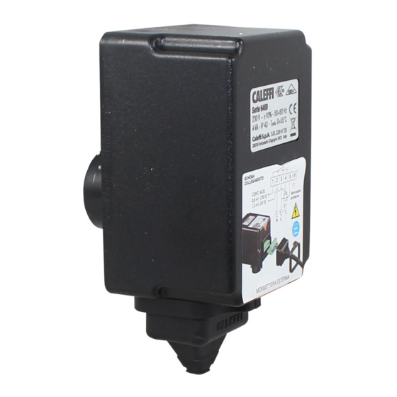
Valvole di zona a sfera motorizzate
Motorised ball zone valves
Motorisierte Zonenkugelventile
Vannes de zone à sphère, motorisées
Válvulas de zona de esfera motorizadas
Válvulas de zona de esfera motorizadas
Gemotoriseerde zoneventielen met kogelafsluiter
©
opyright 2017
alef fi
Funzione
Function
Funktion
Fonction
Función
Função
Werking
Product range
6460
6470
647040
647050
647060
646002
230 V
(ac)
646004
647070
24 V
(ac)
Le valvole di zona permettono l'intercettazione automatica dei circuiti
idraulici negli impianti di climatizzazione.
The zone valves allow for the automatic on/off control of the hydraulic
circuits in heating and air-conditioning systems.
Zonenventile ermöglichen die Zweipunkt-Regelung von hydraulischen
Kreisläufen in Heizungs-und Klimaanlagen.
Les vannes de zone permettent d'assurer l'ârret automatique des
circuits hydrauliques dans les installations de climatisation.
Las válvulas de zona permiten el corte automático de los circuitos
hidráulicos en las instalaciones de climatización.
As válvulas de zona permitem a intercepção automática dos circuitos
hidráulicos nas instalações de climatização.
Zoneventielen maken de automatische afsluiting van de hydraulische
kringen in verwarming- en luchtbehandelingsystemen mogelijk.
6480
648040
1/2"
1/2"
648050
3/4"
3/4"
648060
1"
1"
648070
1 1/4"
1 1/4"
1
www.c leffi.com
6460 - 6470 - 6480 - 6489 series
6490
64904.
1/2"
64905.
3/4"
64906.
1"
68169.11
I
EN
DE
FR
ES
PT
NL
6489
648950
3/4"
Publicidad

Manuales relacionados para CALEFFI 6460 Serie


Resumen de contenidos para CALEFFI 6460 Serie
- Página 1 68169.11 www.c leffi.com Valvole di zona a sfera motorizzate Motorised ball zone valves Motorisierte Zonenkugelventile Vannes de zone à sphère, motorisées Válvulas de zona de esfera motorizadas Válvulas de zona de esfera motorizadas Gemotoriseerde zoneventielen met kogelafsluiter © opyright 2017 alef fi 6460 - 6470 - 6480 - 6489 series Funzione...
- Página 2 Valve technical Materials: - body: brass EN 12165 CW617N - ball: brass EN 12165 CW617N, chrome plated specification - ball seal: PTFE with EPDM O-Ring - stem seal: EPDM double O-Ring - union seal: EPDM O-Ring Medium: water, glycol solutions Max.
- Página 3 Installazione 1 Nel montaggio delle valvole sull’impianto rispettare il senso di flusso delle frecce incise sul corpo. Installation 2 La valvola a due vie può essere installata sia sulla tubazione di mandata Einbau che su quella di ritorno. Installation 3 La valvola a tre vie va installata sulla tubazione di mandata. Instalación Instalação 1 When mounting the valves onto the system respect the flow direction...
- Página 4 5 La valvola a tre vie non può essere trasformata in valvola a 2 vie. 5 The three-way valve cannot be converted into a two-way valve. 5 Das Dreiwege-Ventil kann nicht als Zweiwegeventil genutzt werden. 5 La vanne à trois voies ne peut pas se transformer en vanne à deux voies. 5 La válvula de dos vías se puede transformar en válvula de tres vías y viceversa.
- Página 5 I codoli eccentrici (cod. 648005 - 648006) consentono l'installazione con tutti i tipi di collettori aventi interasse da 50 a 70 mm. The off-centre fittings (code 648005 – 648006) enable installation with all types of manifolds having a centre distance of 50 to 70 mm. Die exzentrischen Adapter (Art.Nr.
- Página 6 Il kit eccentrico cod. 648018 permette l’utilizzo della valvola a tre vie 6480 e del tee 6490 con i collettori semplici. The off-centre kit, code 648018, enables the use of the three-way valve 6480 and the tee-piece 6490 with the simple manifolds. Das Nocken-Set Art.Nr.
- Página 7 1) The valve is supplied in the open position. 2) Check that the drive shaft of the motor is lined up with the proper seat on the valve rod (the actuators are supplied in the “OPEN” position). 3) Thoroughly push the motor onto the valve boss and lock the coupling by inserting the flexible stop into the appropriate hole.
- Página 8 Apertura manuale Rimuovendo il servocomando, la manovra di apertura - chiusura della valvola può essere effettuata manualmente agendo con un cacciavite. Manual Opening Removing the actuator, the opening – closing of the valve can be Manuelle Öffnung performed manually using a screwdriver. Ouverture manuelle Bei Entfernen des Stellantriebs kann das Ventil manuell anhand eines Schraubenziehers geöffnet / geschlossen werden.
- Página 9 La conexión eléctrica del motorreductor se realiza con un sistema toma-clavija, exterior, que no requiere la apertura de la tapa. Con la clavija conectada, deslice la tuerca de protección en caucho, insertándola en el asiento en la ranura correspondiente de la tapa sucesivamente fijar la protección con la banda estrecha en dotación y, como en la imagen, apretar con un destornillador.
- Página 10 Schema interno con valvola in posizione di chiusura - R relè - MC1 microinterruttore fine corsa di apertura. - MC2 microinterruttore fine MC 3 MC 2 MC 1 corsa di chiusura. - MC3 microinterruttore ausiliario libero. A valvola aperta i contatti del microinterruttore libero sono chiusi.
- Página 11 Schema di collegamento termostato ambiente (TA) ed alimentazione elettrica. Il collegamento illustrato consente l’apertura e chiusura della valvola su consenso del termostato ambiente. 1 2 3 4 5 6 Connection scheme with inclusion of the hour counter. The illustrated connection allows for the inclusion of the hour counter (CO) for every opening of the zone valve using the room thermostat...
- Página 12 Connection scheme with inclusion of the hour counter. The illustrated connection allows for the inclusion of the hour counter (CO) for every opening of the zone valve using the room thermostat (TA). The hours totalled by the hour counter can be used as a basis for the distribution of the heating expenses.
- Página 13 1 2 3 4 5 6 1 2 3 4 5 6 Scheme for pump disconnection when no zone is in operation The proposed scheme, using the auxiliary microswitch, allows for the disconnection of the pump when no zone is in operation. If the pump has an absorption greater than 0.8 A (170 VA), it is necessary to use an intermediate contactor.
- Página 14 Sicurezza L’installazione delle valvole di zona deve essere eseguita da parte di personale qualificato in accordo con la vigente normativa. Safety Sicherheit Se le valvole di zona non sono installate, messe in servizio e mantenute correttamente secondo le istruzioni contenute in questo manuale, Sécurité...
- Página 15 Temperaturen über 50°C führen zu schlimmen Verbrühungen. Deshalb während des Einbaus der Inbetriebnahme und der Wartung des Zonenventils immer darauf achten, dass keine Gefahr für die Personen entstehen kann. ACHTUNG: Stromschlaggefahr. Stellantrieb unter Spannung. Unterbrechen Sie die Stromversorgung vor Eingriffen. Nichtbeachtung dieser Hinweise kann Schäden an Personen oder Sachen hervorrufen.
- Página 16 A instalação das válvulas de zona deve ser efectuada por técnicos qualificados e de acordo com as normas em vigor. Se a válvula de zona não for instalada, colocada em funcionamento e mantida correctamente segundo as instruções contidas neste manual, poderá...