Publicidad
Enlaces rápidos
WARNINGS AND CAUTIONS:
• THIS DEVICE MUST BE INSTALLED BY AN ELECTRICIAN.
• TO AVOID FIRE, SHOCK, OR DEATH; TURN OFF POWER AT CIRCUIT BREAKER OR FUSE AND TEST THAT THE POWER IS OFF BEFORE WIRING OR SERVICING!
• TO BE INSTALLED AND/OR USED IN ACCORDANCE WITH ELECTRICAL CODES AND REGULATIONS.
• INSTALL THIS DEVICE ONLY ON A SINGLE BRANCH CIRCUIT PROTECTED BY A FUSE OR A CIRCUIT BREAKER.
• USE THIS DEVICE ONLY WITH COPPER OR COPPER CLAD WIRE.
• TO MAINTAIN ENVIRONMENTAL RATING, IT IS THE RESPONSIBILITY OF THE ELECTRICIAN TO ATTACH THIS DEVICE USING APPROVED METHODS FOR THE INTENDED APPLICATION.
DESCRIPTION:
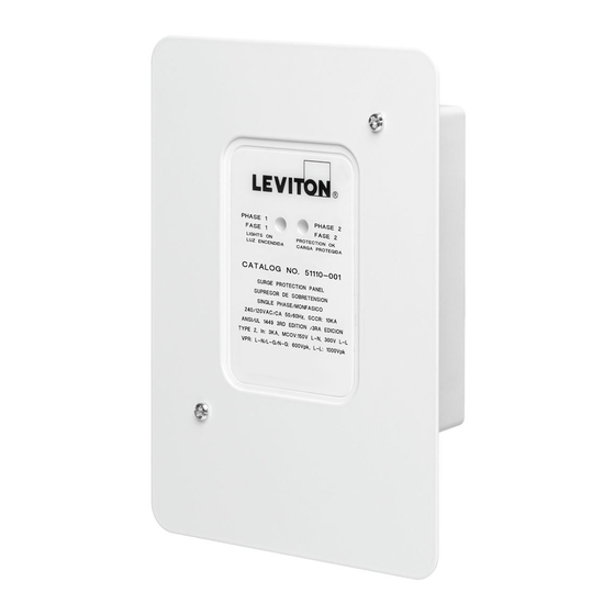
Leviton's 51110-SRG Residential Panel Surge Protection Device (SPD) is a high-performance Transient Voltage Surge Suppressor. The Residential Panel
SPD unit is designed for use on 240/120 VAC at the home's breaker panel. Diagnostics provide visual indicators for monitoring the 240/120 VAC protection
status.
TO INSTALL:
1. RESTORE POWER, if necessary.
2. Verify that the electrical system in use is 240/120 VAC single phase by the safe and proper use of AC Voltage Measurement Equipment.
3. TURN OFF POWER.
4. Identify the device or load to be protected. Locate the SPD unit as close as possible to the electrical panel serving the loads to be protected, to
minimize the effects of connection lead-length resistance and inductance.
WARNING: Matching the SPD model and electrical system line voltage is critical! Identify the system to be protected by measuring L-N and L-L
voltages. Use extreme caution while making voltage measurements! Confirm that the maximum measured voltage does not exceed the maximum
continuous line voltage specified for the 51110-SRG unit to be installed or damage will occur. Figure 1 illustrates the wiring connection for the 51110-
SRG.
5. Leads shall be 12 AWG 18" maximum. Leads from the SPD must be connected to the power mains through a 20 Amp (maximum) disconnect and
fusing means. Either dedicated branch circuit breakers (independent single-pole preferred), or a fused disconnect switch may be used. When the
SPD device shares a 2-pole ganged breaker, National Electric Code (NEC) and local requirements shall prevail. NOTE: Sharing of breakers is not
permitted by CEC in Canada.
NOTE: For best performance, installation wires should be twisted or bound together and as short as possible. Leads from the SPD should be bundled
together and secured with cable ties when possible. Conduit shall be used where required by code. For best suppression, the cable and some
cable ties may be cut down from the supplied length to allow for a shorter installation path.
6. Mount the SPD unit securely. The 51110-SRG unit can be surface mounted by removing the cover, inserting screws through the two holes provided,
tightening them to secure the unit, then replacing the cover. The SPD unit can also be flush mounted by mounting the unit to a depth of 1 5/8 inches
[4.1 cm] (maximum), then, when the cover is replaced, it should be flush with the outer wall. Direct panel mounting applications should utilize a 7/8" (2.2
cm) conduit knockout hole with the threaded nipple (provided).
7. The wires should be routed to the circuit breaker terminals (refer to Figure 1) using the shortest path (cutting excess wire length) to the power line. If
conduit is used, use conduit as required by NEC and local requirements. Avoid sharp bends. Lead wire insulation should not be cut or damaged.
8. Connection: Connect the black wire (marked "Line 1") to one line, and the other black wire (marked "Line 2") to the other line. These Black wires may
be connected to either L1 or L2 without regard to phase angle.
9. The white wire should be connected to the system's Neutral bus.
10. The green wire is attached internally to the 51110-SRG unit's ground. The green wire must be grounded to the electrical panel's ground bus.
11. Check that all connections are correct, tight, and secure.
POWER ON:
1. Activate the system by turning power ON (closing any main and SPD circuit breakers). The green indicator lights should be ON. If indicator lights are not
ON, call technical support.
RESIDENTIAL PANEL SURGE PROTECTIVE DEVICE (SPD)
Figure 1 – Electrical Wiring Diagram
Figure 1 – Schéma de câblage électrique
Figura 1 – Diagrama de Cableado Eléctrico
Black / Noir / Negro
L
CB
Black / Noir / Negro
L
CB
White / Blanc / Blanco
N
Green / Vert / Verde
G
Suitable for use on a circuit capable of delivering no more than 10000
RMS symmetrical amperes, 240 volts maximum when protected by a 20
amp circuit breaker rated 240 volts maximum. The interupt rating of the
fuse or circuit breaker shall not be less than the available fault current.
Dispositif convenant aux circuits capables de livrer un courant maximal de 10000
ampères symétriques efficaces, à 240 volts au plus protégés par un fusible
ou un disjoncteur de 20 A ayant cette tension nominale. La capacité
nominale de sectionnement des fusibles ou des disjoncteurs employés ne
peut être inférieure au courant de fuite possible.
Compatible para usar en un circuito capaz de repartir no más de 10000 amperios
simétricos RMS, 240 voltios máximo cuando está protegido por un interruptor de
circuitos de 20 amperios de capacidad de 240 voltios máximo. El grado de interrupción
del interruptor de circuitos o fusible no debe ser menor que la falla de corriente.
For Technical Assistance Call: 1-800-824-3005 (U.S.A. Only)
Cat No. 51110
INSTALLATION
www.leviton.com
51110-SRG
DI-R02-51110-21A
ENGLISH
Publicidad

Manuales relacionados para Leviton 51110


Resumen de contenidos para Leviton 51110
- Página 1 Use extreme caution while making voltage measurements! Confirm that the maximum measured voltage does not exceed the maximum continuous line voltage specified for the 51110-SRG unit to be installed or damage will occur. Figure 1 illustrates the wiring connection for the 51110- SRG.
- Página 2 El conductor blanco debe estar conectado al eje neutro del sistema. Mettre le système sous tension en rétablissant le courant (aux disjoncteurs 10. El conductor verde se une internamente a la tierra de la unidad 51110-SRG. El principaux ou dédiés). Les témoins verts devraient alors s’allumer. Dans le cas conductor verde debe estar conectado al eje a tierra del panel eléctrico.