Publicidad
Enlaces rápidos
WARNINGS & CAUTIONS:
• TO AVOID FIRE, SHOCK, OR DEATH; TURN OFF POWER AT CIRCUIT BREAKER OR FUSE AND TEST THAT
THE POWER IS OFF BEFORE WIRING OR WORKING ON A SPD DEVICE!
• TO BE INSTALLED AND/OR USED IN ACCORDANCE WITH ELECTRICAL CODES AND REGULATIONS.
• IF YOU ARE NOT SURE ABOUT ANY PART OF THESE INSTRUCTIONS, CONSULT AN ELECTRICIAN.
• THIS DEVICE IS NOT A LIGHTNING ARRESTER, AND WILL NOT SURVIVE LIGHTNING STRIKES IN CLOSE
PROXIMITY TO THE PREMISES OR SUSTAINED OVERVOLTAGES.
• THIS DEVICE IS DESIGNED FOR USE IN EQUIPMENT OR INSTALLATIONS REQUIRING A PERMANENT
HARD-WIRED DEVICE.
• FOR 51015-WM ONLY – THIS DEVICE MUST NEVER BE INSTALLED ON A LINE THAT IS NOT SERVED BY
DISCONNECT MEANS, SUCH AS 15-AMP CIRCUIT BREAKERS OR 15-AMP FUSED DISCONNECT SWITCHES.
• FOR 51020-WM ONLY – THIS DEVICE MUST NEVER BE INSTALLED ON A LINE THAT IS NOT SERVED BY
DISCONNECT MEANS, SUCH AS 20-AMP CIRCUIT BREAKERS OR 20-AMP FUSED DISCONNECT SWITCHES
• OPERATE INDOORS BETWEEN 30-90% RELATIVE HUMIDITY.
• USE THIS DEVICE ONLY WITH COPPER OR COPPER CLAD WIRE.
INTRODUCTION
Transient voltage surges are short-term deviations from a desired voltage level or signal that can occur at any time.
Such changes can result in an electronic device malfunction or cause extensive damage. Also termed "spikes", these
occurrences take place as a result of magnetic field/inductive coupling or whenever the line current is interrupted. They
can originate from either inside a facility or derive from outside utility lines. Sources within a facility involve loads that are
switched, such as electric motors that are turned ON and OFF. Outside transient influences involve utility grid switching.
DESCRIPTION
Leviton's Wired Modules, Cat. Nos. 51015-WM, 51020-WM and 51020-DIN, are ideally suited for use by Original
Equipment Manufacturers (OEM's) who wish to provide superior SPD protection for their equipment.
FEATURES
• cURus Type 4 SPD.
• I EEE C62.41-1991 category A&B combination wave and ringwave suppression.
• Three protection modes – L-N, L-G, N-G.
• Two suppression stages – primary and backup.
• Fused for suppression protection failure.
• EMI/RFI filtration circuitry.
• T hree diagnostic modes include LED indicators for phase-neutral polarity reversal, open ground and suppression
failure. Suppression failure also has an audible indicator.
• 48-62 Hz operation.
• Location per IEC std: Class III.
• One port.
TO INSTALL
System Voltage and Current Requirements:
1. D etermine the system voltage of the equipment to be protected. The Wired Modules are rated for 120V single phase
line-to-neutral with a ground return.
2. Determine the current rating of the equipment to be connected.
3. The Wired Modules are series connected devices. Cat. No. 51015-WM is rated for 15 Amp maximum load. Cat. No.
51020-WM is rated for 16 Amp maximum load. Be aware of the line and load side designations.
4. The line side (power input) has two terminals: L-Line in and N-Neutral in.
5. The load side (power output) has two terminals: L-Line out and N-Neutral out.
6. Line and Load side terminal blocks should use #12-#8 AWG wires, secured to terminals using 12 in.-lbs. of torque.
The grounding terminal block is suitable for use with #14-#10 AWG copper wire when torqued to 35 in.-lbs., and is
suitable for use with #8-#6 AWG copper wire when torqued to 45 in.-lbs.
7. T here is a single-point ground terminal located on the top side of the housing. All input and output ground connections
must be made at this terminal.
8. Connect the Wired Modules as follows: Figure 2 shows a single phase line-to-neutral installation of Cat. No.
51020-WM. Figure 3 shows a 3 phase line-to-neutral installation utilizing three Cat. No. 51020-WMs.
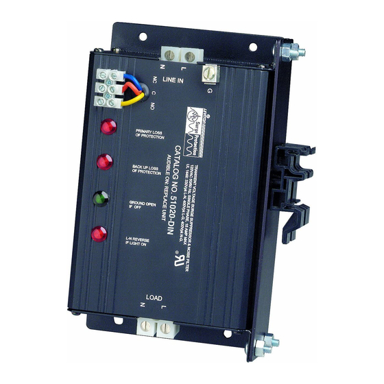
9. A ssembly (51020-DIN): Enclosed DIN clip hardware may be used to mount the module on its side using a DIN rail,
as shown in Figure 1.
10. 5 1020-DIN should be pushed gently into place onto a DIN rail. This module will attach to a 35 mm standard DIN Rail
(DIN EN 50022) or a (32 mm "G" DIN Rail (DIN EN 50035).
Power ON Diagnostics:
1. Turn power ON and check the diagnostic lights. If the Module is properly installed and the system wiring is correct,
the Green ground LED will be lit. This signifies that power is ON and ground continuity exists between the protected
equipment and the building power source.
2. I f the power is OFF, the Green ground LED and the Red polarity LED will be OFF.
3. I f power is present and the Red polarity LED is lit, but the Green ground LED is OFF, it signifies that power is present
but Hot and Neutral wiring is reversed in polarity or an open ground condition exists. This could be due to a reversal
somewhere in the building wiring, an open ground or an error in the Wired Module connections.
NOTE: THIS IS A POTENTIALLY UNSAFE CONDITION AND SHOULD BE CORRECTED IMMEDIATELY.
4. R elay status circuit and contacts are rated at 5 Amps. The voltage rating is 250VAC/30VDC. Contacts accomodate
#20-#12 AWG wire secured to terminals using 3.5 lb.-in. of torque. If both primary and secondary surge suppression
fail, continuity will be between the "NO" and "C".
Surge Protection Diagnostics:
The Wired Modules include two levels of surge protection: primary and backup. Illuminated Red LEDs and an audible
tone indicate surge suppression failure has occurred. The audible tone provides failure warning when the Wired Module
is contained within a piece of equipment and the LEDs are not readily visible.
1. U nlit RED LEDs and absence of audible tone indicate primary and backup surge protection circuitry is in working
order.
2. If either one of the RED Protection LED's are lit and there is an audible tone, it signifies loss of either primary or
backup protection. Backup surge suppression can be relied on temporarily, but the Wired Module should be replaced
as soon as possible.
3. I f both RED Protection LEDs are lit and there is an audible tone, all surge protection has failed, but power will
continue to be applied to the load. If either step 2 or step 3 has occured, a transient surge has exceeded the rating of
the Wired Modules and they should be replaced immediately.
NOTE: THIS IS A POTENTIALLY UNSAFE CONDITION AND SHOULD BE CORRECTED IMMEDIATELY.
Leviton warrants to the original consumer purchaser and not for the benefit of anyone else that this product at the time of its sale by Leviton is free of defects in materials and workmanship under normal and proper use for 10 years from
the purchase date. Leviton's only obligation is to correct such defects by repair or replacement, at its option, if within such 10 year period the product is returned prepaid, with proof of purchase date, and a description of the problem to
Leviton Manufacturing Co., Inc., Att: Quality Assurance Department, 201 North Service Road, Melville, New York 11747. This warranty excludes and there is disclaimed liability for labor for removal of this product or reinstallation.
This warranty is void if this product is installed improperly or in an improper environment, overloaded, misused, opened, abused, or altered in any manner, or is not used under normal operating conditions or not in accordance with any
labels or instructions. There are no other or implied warranties of any kind, including merchantability and fitness for a particular purpose, but if any implied warranty is required by the applicable jurisdiction, the duration of any
such implied warranty, including merchantability and fitness for a particular purpose, is limited to 10 years. Leviton is not liable for incidental, indirect, special, or consequential damages, including without limitation, damage to, or
loss of use of, any equipment, lost sales or profits or delay or failure to perform this warranty obligation. The remedies provided herein are the exclusive remedies under this warranty, whether based on contract, tort or otherwise.
Wired Modules
Cat. Nos. 51015-WM; Rated: 15A-120V
51020-WM; Rated: 16A-120V
51020-DIN; Rated: 16A-120V
INSTALLATION
Wired Module
Module câblé
Módulo Cableado
Figure 2 – Single Phase, Line-to-Neutral installation of a 51020-WM Wired Module.
Figure 2 – Installation monophasée « ligne à neutre » d'un module 51020-WM.
Figura 2 – Instalación Línea a Neutro de Fase Sencilla del módulo cableado 51020-WM.
Figure 3 – Three Phase, Line-to-Neutral installation using three 51020-WM Wired Modules.
Figure 3 – Installation triphasée « ligne à neutre » de trois modules 51020-WM.
Figura 3 – Instalación Línea a Neutro, de Tres Fases, usando tres módulos cableados 51020-WM
From Line
De la source
d'alimentation
De la línea
LIMITED 10 YEAR WARRANTY AND EXCLUSIONS
For Technical Assistance Call:
1-800-824-3005 (U.S.A. Only)
1 800 405-5320 (Canada Only)
www.leviton.com
Figure 1 – 51020-DIN Installation
Figure 1 – Installation du 51020-DIN
Figure 1 – Instalación del 51020-DIN
Line In
Entrée de Ligne
Entrada de Línea
From Line
Cat. No.
L
CB
L
De la source
51020-WM
N
N
d'alimentation
De la línea
G
NC C NO
Relay Status Contacts
Contacts d'état
des relais
Contactos del estado
del relevador
NOTE: Cat. No. 51015-WM & 51020-DIN Wired Module installation is similar.
REMARQUE : l'installation du modèle 51015-WM et 51020-DIN est similaire.
NOTA: La instalación del Módulo No. de Cat. 51015-WM y 51020-DIN es similar.
Line In
Entrée de Ligne
Entrada de Línea
Line In
Entrée de Ligne
Entrada de Línea
L1
CB
L2
CB
L3
CB
N
Line In
Entrée de Ligne
Entrada de Línea
NOTE: Cat. No. 51015-WM & 51020-DIN Wired Module installation is similar.
REMARQUE : l'installation du modèle 51015-WM et 51020-DIN est similaire.
NOTA: La instalación del Módulo No. de Cat. 51015-WM y 51020-DIN es similar.
PK-93730-10-02-0B
English
(
4) #10-32 Screws
Vis 10-32 (4)
Tornillos #12-32 (4)
(4) Washers
Rondelles (4)
Arandelas (4)
DIN Rail Clip
Agrafe pour rails DIN
Gancho de riel DIN
(4) #10-32 Nuts
Écrous 10-32 (4)
Tuercas #10-32 (4)
Load
Charge
Carga
To Load
L
L
Vers les
N
N
charges
120V
A carga
Load
Charge
Carga
L
Cat. No.
Load 1
L1
L
Charge 1
51020-WM
N
L2
N
Carga 1
120V
G
SPD Module 1 (L1- N)
Module DLST 1 (L1-N)
Módulo PSTT 1 (L1-N)
Load
Charge
Carga
Load 2
L
Cat. No.
L1
L
Charge 2
51020-WM
N
L2
N
Carga 2
120V
G
SPD Module 2 (L2- N)
Module DLST 2 (L2-N)
Módulo PSTT 2 (L2-N)
Load
Charge
Carga
L
Cat. No.
Load 3
L1
L
Charge 3
51020-WM
N
L2
N
Carga 3
120V
G
SPD Module 3 (L3- N)
Module DLST 3 (L3-N)
Módulo PSTT 3 (L3-N)
Publicidad

Manuales relacionados para Leviton 51015-WM


Resumen de contenidos para Leviton 51015-WM
- Página 1 Tornillos #12-32 (4) • THIS DEVICE IS DESIGNED FOR USE IN EQUIPMENT OR INSTALLATIONS REQUIRING A PERMANENT Wired Module HARD-WIRED DEVICE. Module câblé • FOR 51015-WM ONLY – THIS DEVICE MUST NEVER BE INSTALLED ON A LINE THAT IS NOT SERVED BY Módulo Cableado (4) Washers DISCONNECT MEANS, SUCH AS 15-AMP CIRCUIT BREAKERS OR 15-AMP FUSED DISCONNECT SWITCHES. Rondelles (4) • FOR 51020-WM ONLY – THIS DEVICE MUST NEVER BE INSTALLED ON A LINE THAT IS NOT SERVED BY...
- Página 2 à gagner, et tout dommage-intérêt découlant du délai ou du défaut de l’exécution des obligations de cette garantie. Seuls les recours stipulés dans les présentes, qu’ils soient d’ordre contractuel, délictuel ou autre, sont offerts en vertu de cette garantie.