Tabla de contenido
Publicidad
Idiomas disponibles
Idiomas disponibles
Enlaces rápidos
ReAd INstRuctIONs cAReFullY: Read and follow all instructions. Place instructions in a safe
place for future reference. Do not allow anyone who has not read these instructions to assemble,
light, adjust or operate the heater.
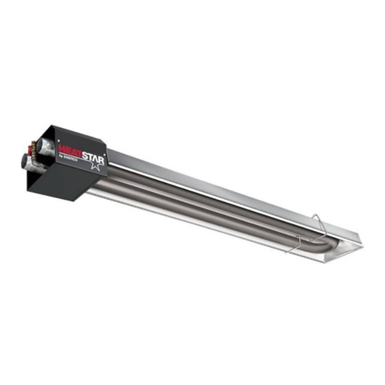
Gas-Fired, Low-Intensity Infrared Heaters
approved for Commercial Applications
WARNING:
Improper installation, adjustment, alteration, service or maintenance can
cause injury or property damage. Refer to this manual. For assistance or
additional information consult a qualified installer, service agency or the gas supplier.
— WHAT TO DO IF YOU SMELL GAS
•
Open Windows
DO NOT try to light any appliance.
•
DO NOT use electrical switches.
•
DO NOT use any telephone in your house. Immediately call your local gas supplier from a
•
neighbor's telephone. Follow the gas supplier's instructions.
Do not touch any electrical switch; do not use any phone in your building.
•
Installation and service must be performed by a qualified installer, service agency or the gas
•
supplier.
If you cannot reach your gas supplier, call the Fire Department.
•
FOR YOUR SAFETY:
Do not store or use gasoline or other flammable vapors and liquids in the vicinity of this
or any other appliance.
WARNING: If the information in these instructions are not followed exactly, a fire or
explosion may result causing property damage, personal injury or loss of life.
OpeRAtING INstRuctIONs
ANd OWNeR's MANuAl
Heatstar, Inc., 4560 W. 160TH ST., CLEVELAND, OHIO 44135 • 866-477-2194
Model #
HST45
LANGUAGES
ENGLISH
Pages E1 — E24
SPANISH
Pages S1 — S24
FRENCH
Pages F1 — F24
2017-02853-CB
Publicidad
Capítulos
Tabla de contenido
Solución de problemas

Manuales relacionados para HeatStar HST45


Resumen de contenidos para HeatStar HST45
- Página 1 WARNING: If the information in these instructions are not followed exactly, a fire or explosion may result causing property damage, personal injury or loss of life. 2017-02853-CB Heatstar, Inc., 4560 W. 160TH ST., CLEVELAND, OHIO 44135 • 866-477-2194...
-
Página 2: Tabla De Contenido
WARNING: WARNING: YOUR SAFETY IS IMPORTANT TO YOU AND TO OTHERS, FIRE, BURN, INHALATION, AND EXPLOSION HAZARD. SO PLEASE READ THESE INSTRUCTIONS BEFORE YOU KEEP SOLID COMBUSTIBLES, SUCH AS BUILDING OPERATE THIS HEATER. MATERIALS, PAPER OR CARDBOARD, A SAFE DISTANCE AWAY FROM THE HEATER AS RECOMMENDED BY THE INSTRUCTIONS NEVER USE THE HEATER IN SPACES WHICH DO OR MAY CONTAIN VOLATILE OR AIRBORNE... -
Página 3: Before You Begin
BeFORe YOu BeGIN Available Accessories Read this manual carefully before installing or servicing this Vent Kit (F102848) equipment. Improper installation, servicing or maintenance will cause death, injury or property damage. Check the minimum 1. (2) 4" x 2' Pipe 26GA. required safe distances from combustibles given on the outside 2. - Página 4 About the Heater Burner Box Front Fixed Hanger Reflector Heat Exchanger Rear Movable Hanger Control Side Access Burner Box Contains the electrical components (i.e. blower motor, power transformer, etc.) and gas distribution components (i.e. gas valve, etc.) that make the heater work. There are no owner serviceable items contained in this box. Front Fixed Hanger Provides rigid support and mounting surface for the reflector.
-
Página 5: Heater Specifications
Weight Length Model No. BTU/hr Weight Length 45,000 96 lbs. 10’ 45,000 96 lbs. HST45 HST-45 45,000 96 lbs. VeNtING specIFIcAtIONs HeAteR specIFIcAtIONs Vent/Flue Electrical Length – 25 feet (Maximum) Rating: 120VAC, 60Hz, single phase, 1 amp 5 feet (Minimum) Connection: 3 pin molded plug Flue Pipe –... -
Página 6: Section 2 Planning
Where can the heater be installed? section 2 plANNING The MHT tube heater is intended for installation in the following General areas: • Light industrial/commercial applications, such as: This section provides the following information: — • entranceways Defines the gas, electric and venting requirements for the MHT tube heater. -
Página 7: Venting Requirements
electrical service Requirements: Non-residential Installations: system Requirements Aircraft Hangars The MHT tube heater may be used in certain areas of aircraft The MHT tube heater requires a grounded three-prong electrical hangars. Installation in aircraft hangars must be in accordance with outlet to be installed within 18 inches of the rear surface of the the following codes: United States: Refer to Standard for Aircraft heater’s burner box. -
Página 8: Section 3 Installation
section 3 INstAllAtION Installation Materials Materials required for the installation of the MHT tube heater include at a minimum the following: WARNING Several steps are involved in the installation of the heater. • High temperature silicone sealant DO NOT attempt to operate the heater until ALL steps of •... -
Página 9: General Guidelines
General Guidelines damage. Clearances from vehicles parked beneath heaters must be maintained. Signs should be posted to identify any possible Regardless of the venting arrangement that will be connected to the violation of the clearance distances form the heater in the vehicle heater, the following general guidelines for venting must be followed: areas. -
Página 10: Horizontal Installation
Hang the Heater Horizontal Installation Installation locations come in a variety of sizes, shapes, styles and 1. Using S-hooks, attach two equal lengths of 2/0 chain, or methods of construction. Because of all these variables, it is not equivalent, to the two uppermost holes in the front fixed hanger. possible to include mounting hardware with the MHT heater. - Página 11 MHt HeAteR AsseMBlY INstRuctIONs 1. Place gaskets from Gasket kit (02885) on each side of the burner box. Use the four mounting studs around each of the three-inch holes for location. 2. Slide the tube flanges over the studs as was done in the prior step with the gaskets.
-
Página 12: Typical Installation
typical Installation section 4 VeNtING The Illustration below shows a typical installation of the This appliance is certified under the ANS/CSA Standard for Vented MHT tube heater. The installation drawing shown has a straight Gas-Fired Space Heating Appliances. In accordance with these horizontal venting arrangement and specifies the minimum space standards all sidewall venting must conform to the supplied diagram required for maintenance, as well as the allowable range of distances... - Página 13 The seams along the length of the piping and the joints BAsIc Flue VeNtING between sections of piping should be sealed to prevent a • Venting must be in compliance with the latest edition of the potential leakage of flue gas into building. Use 100% RTV National Fuel Gas Code (ANSI.
- Página 14 NOTE: To minimize problems associated with MINIMUM HEIGHT FROM ROOF condensation in long runs, vent pipe can be TO LOWEST DISCHARGE OPENING insulated. Roof Pitch H (Min) 3. The horizontal venting system approved with this heater consists Flat to 6/12 1.0 Feet of the Side Wall Vent Kit (02840) shown are page 3.
- Página 15 a) Be sure that method selected for venting heater complies with gases. a) Be sure that method selected for venting heater complies with all Single Wall codes as required for each particular location. Single wall vent run Single wall terminal end b) Exhaust end of heater will accept a three (3") inch flue pipe using the flue pipe adapter.
-
Página 16: Air For Combustion
Vertical Venting VERTICAL THROUGH THE ROOF Vent Cap (Leslie VersaCap) 3" Dia. Single-Wall Pipe 3' Min. 6" Min. Flashing ¼” per ft. 3" Starting Collar downwards Air For combustion If indoor combustion air is to be supplied for a tightly enclosed area, one square inch of free area opening shall be provided below the heater for each 1,000 Btu/hr of heater input. - Página 17 Low Voltage Thermostat Wiring Diagram CAUTION Label all wires prior to disconnection when Heaters are normally controlled by thermostat. The servicing controls. wiring errors can cause improper and recommended 24V thermostat, connects to the dangerous operation. Verify proper operation after servicing. unit as shown in the diagram below.
-
Página 18: Section 5 Operation
and fittings should be new and free from defects. Carefully ream the pipe and tube ends to remove obstructions and burrs. 3. Use LP-resistant joint compound on all threads. 4. Check the pipe and tube connections for leaks before placing heating equipment into service. -
Página 19: Operation Of The Heater
Operation of the Heater 1. A qualified service agency should be contacted for service other than routine maintenance. CHILDERN AND ADULTS SHOULD BE ALERTED TO THE HAZARDS OF HIGH SURFACE TEMPERATURES AND SHOULD STAY AWAY TO AVOID WARNING Turn off the gas and electrical supplies to BURNS OR CLOTHING IGNITION. -
Página 20: Section 7 Troubleshooting
section 7 tROuBlesHOOtING General This troubleshooting quide has been designed to assist you in locating and correcting minor problems that may occur with the MHT tube heater. BLOWER DOES NOT COME ON Possible Cause Try This…. Power cord is not plugged in. Plug power cord into a grounded three prong Outlet. - Página 21 BURNER DOES NOT LIGHT Possible Cause Try This…. Air in the gas line. Purge gas lines. Check gas inlet pressure at the 1/8” NPT plugged tap. Gas inlet Improper gas inlet pressure. pressure should be as follows: Natural Gas: 5.0”w.c. min.; 10.5” max. LP Gas: 1 1”w.c.
-
Página 22: Section 8 Illustrated Parts
section 8 IllustRAted pARts Illustrated parts This section provides the part numbers and pictorials for components of the MHT tube heater. Callout letters on the illustrations are keyed to the associated parts list. IteM pARt NuMBeR descRIptION MHt-45 02808 Spark Electrode 02837 Ignition Wire 05795... - Página 23 Heatstar • Model #HST 45 Tube Heater REPLACEMENT PARTS LIST FOR HEATER MODEL MHT TUBE HEATER REF.# ITEM# DESCRIPTION F102850 MHT-45NG Burner Box for (F208850) F102851 MHT-45LP Burner Box for (F202851) F106250 MHT-45 Tube Set 06014 Hanger 06016 Hanger Clamp...
-
Página 24: Warranty
This Warranty gives you specific legal rights, and you may have other rights which vary from state to state. Heatstar, Inc. reserves the right to make changes at any time, without notice or obligation, in colors, specifications, accessories, materials and models. -
Página 25: Calentadores De Gas, De Baja Intensidad De Infrarrojos Aprobado Para Aplicaciones Comerciales
ADVERTENCIA: Si no se siguen al pie de la letra las instrucciones de este manual, podría producirse un incendio o una explosión que provocaría daños materiales, lesiones o muertes. Heatstar, Inc., 4560 W. 160TH ST., CLEVELAND, OHIO 44135 • 866-477-2194 2017-02853-CB... -
Página 26: Advertencia General De Peligro
ADVERTENCIA: ADVERTENCIA: SU SEGURIDAD ES IMPORTANTE PARA USTED Y PARA LOS PELIGRO DE INCENDIO, QUEMADURAS, INHALACIÓN Y DEMÁS. POR ELLO, LEA ESTAS INSTRUCCIONES ANTES DE EXPLOSIÓN. MANTENGA LOS COMBUSTIBLES SÓLIDOS, UTILIZAR EL CALENTADOR. TALES COMO MATERIALES DE CONSTRUCCIÓN, PAPEL O CARTÓN, A UNA DISTANCIA SEGURA DEL CALEFACTOR. -
Página 27: Sección 1 Introducción
ANTEs DE ComENZAR Accesorios disponibles Lea atentamente este manual antes de instalar o hacerle el Juego de ventilación (F102848) mantenimiento a este equipo. La instalación, el servicio o mantenimiento inadecuados pueden causar muertes, lesiones o 1. (2) Tubo 26GA de 7,62 cm x 5,08 cm (4" x 2') daños materiales. -
Página 28: Acerca Del Calentador
Acerca del calentador Caja del quemador Gancho fijo delantero Reflector Intercambiador de calor Gancho posterior móvil Acceso de control lateral Caja del quemador Contiene los componentes eléctricos (por ejemplo, motor del soplador, transformador, etc.) y los componentes de la distribución de gas (por ejemplo, válvula de gas, etc.) que hacen funcionar el calentador. No contiene elementos a los que el usuario pueda realizarle mantenimiento Gancho fijo delantero Proporciona soporte rígido y superficie de montaje para el reflector. -
Página 29: Especificaciones Técnicas
Especificaciones técnicas: Longitud 29,21 cm (11 ½") 2,54 cm (1") Máx. Reflector Puntos de suspensión Caja del Intercambiador de calor quemador - Vista lateral - 34,3 cm (13 ½") - Vista del extremo - 22,86 cm (9") Detalles importantes Modelo N. °... -
Página 30: Responsabilidades Del Instalador
¿Dónde se puede instalar el calentador? sección 2 PlANIFICACIóN General El calentador de tubo MHT es apto para ser instalado en las siguientes áreas: Esta sección proporciona la siguiente información: • Aplicaciones industriales y comerciales, como: • Define los requisitos de gas, electricidad y ventilación para el —... -
Página 31: Requisitos Del Sistema Eléctrico: Requisitos Del Sistema
Requisitos del sistema eléctrico: Instalaciones no residenciales: Requisitos del sistema Hangares para aviones El calentador de tubo MHT requiere que se instale un tomacorriente El calentador de tubo MHT se puede utilizar en algunas áreas de los hangares para aviones. La instalación en hangares para eléctrico de tres patas conectado a tierra dentro de los 45,72 cm. -
Página 32: Sección 3 Instalación
sección 3 INsTAlACIóN materiales para la instalación Los materiales que se necesitan para la instalación del calentador de tubo MHT incluye, como mínimo los siguientes elementos: ADVERTENCIA Existen varios pasos para la instalación del calentador. NO • Sellador de silicona de alta temperatura intente utilizar el calentador hasta que no se hayan realizado TODOS los pasos de la instalación. -
Página 33: Indicaciones Generales
Indicaciones generales Es importante mantener siempre las distancias seguras mínimas requeridas desde los combustibles para evitar muertes, lesiones o daños materiales. Se Independientemente de la ventilación que se conecte al calentador, se deben mantener las distancias desde los vehículos estacionados debajo de los deben seguir las siguientes indicaciones generales de ventilación: calentadores. -
Página 34: Procedimiento Para Colgar El Calentador
Procedimiento para colgar el calentador Instalación horizontal Los lugares de montaje tienen tamaños, formas, estilos y métodos de 1. Con ganchos en forma de S, fije dos tramos de cadena iguales construcción variados. Debido a todas estas variables, no se pueden de 2/0, o equivalente, a los dos orificios más altos del gancho fijo incluir los accesorios de montaje con el calentador MHT/HST. -
Página 35: Instrucciones Para El Ensamblaje Del Calentador Mht
INsTRuCCIoNEs PARA El ENsAmBlAJE DEl CAlENTADoR mHT 1. Coloque las juntas del juego de juntas (02885) a cada lado de la caja del quemador. Utilice las cuatro vigas de montaje alrededor de cada orificio de 7,62 cm. (tres pulgadas) para la ubicación. 2. -
Página 36: Instalación Típica
Instalación típica sección 4 VENTIlACIóN La siguiente ilustración muestra una instalación típica del calentador de Este artefacto está certificado según las Normas ANS/CSA para tubo MHT. El dibujo de instalación que se muestra tiene una colocación artefactos de calefacción a gas ventilados. De acuerdo con estas de ventilación horizontal recta y especifica el espacio mínimo que normas, todas las ventilaciones para paredes laterales deben cumplir se necesita para el mantenimiento, así... -
Página 37: Ventilación Básica Del Respiradero
VENTIlACIóN BÁsICA DEl REsPIRADERo 5. Las juntas entre las secciones de la tubería se deben ajustar con tornillos de chapa metálica u otros medios aprobados. Las costuras a lo largo de la tubería y las juntas entre las • La ventilación debe cumplir con la última edición del Reglamento secciones de la tubería se deben sellar para evitar posibles fugas nacional de combustible gaseoso (ANSI. -
Página 38: Altura Mínima Desde El Techo Hasta La Abertura De Descarga Más Baja
para una tapa de ventilación aprobada tiene -- 3,1 m (10 pies) ALTURA MÍNIMA DESDE EL TECHO HASTA LA ABERTURA DE DESCARGA MÁS BAJA EJEmPlo para un circuito horizontal tiene -- 4,57 m (15 pies) Inclinación del techo Alt (Mín) Su longitud equivalente máxima es de -- 7,62 m (25 pies) Plano a 6/12 0,30 m. -
Página 39: Colocación Alternativa /Equipo Opcional Para La Ventilación
El calentador se debe ventilar de acuerdo con la especificación ANSI de la ventilación para una instalación adecuada. El calentador se debe ventilar de acuerdo con la especificación ANSI b) Se necesita una tubería de respiradero de 7,62 cm (3 pulgadas) Z223.1, última revisión. - Página 40 Ventilación vertical suministro de aire exterior para la combustión hacia el calentador. Para un suministro de aire exterior, se puede fijar una tubería para paredes simples de 7,62 cm (3"). El conducto puede tener hasta 7,62 metros (25 pies) de longitud como máximo o 0,6 metros (2 pies) de longitud como mínimo con no más de dos (2) codos.
-
Página 41: Calentador (Máximo 1 Por Termostato)
Diagrama del cableado del termostato de bajo voltaje CUIDADO: Etiquete todos los cables antes de la desconexión Generalmente el termostato controla los calentadores. cuando se realicen controles de mantenimiento. Verifique El termostato de 24V recomendado, se conecta a la unidad que el artefacto funcione adecuadamente después del mantenimiento. -
Página 42: Sección 5 Funcionamiento
2. Utilice tuberías de hierro o acero forjados y acoples de hierro maleable. Se pueden utilizar caños de cobre y acoples de bronce siempre que su uso cumpla con los códigos locales. Todas las tuberías, caños y acoples deben ser nuevos y no tener defectos. Limpie cuidadosamente los extremos de la tubería y los caños para quitar las obstrucciones y las rebabas. -
Página 43: Funcionamiento Del Calentador
Funcionamiento del calentador (CUIDADO) Etiquete todos los cables antes de la desconexión cuando se realicen controles de mantenimiento. TANTO LOS ADULTOS COMO LOS NIÑOS DEBEN ESTAR ATENTOS Para obtener el mejor rendimiento, los siguientes procedimientos de A LOS PELIGROS DE LAS ALTAS TEMPERATURAS DE SUPERFICIE Y mantenimiento deben ser realizados por una agencia de reparación DEBEN MANTENER DISTANCIA PARA EVITAR QUEMADURAS O LA calificada antes de cada temporada de calefacción:... -
Página 44: Sección 7 Resolución De Problemas
sección 7 REsoluCIóN DE PRoBlEmAs General Esta guía de resolución de problemas fue diseñada para ayudarlo a localizar y corregir problemas sencillos que pueden aparecer en el calentador de tubo MHT/HST. EL SOPLADOR NO SE ENCIENDE Posible causa Intente esto… El cable de alimentación está... -
Página 45: El Quemador No Enciende
EL QUEMADOR NO ENCIENDE Posible causa Intente esto… Hay aire en la línea de gas. Purgue las líneas de gas. La presión de entrada de gas no es adecuada. Verifique la presión de entrada de gas en la tapa de cierre de 0,12 cm (1/8") NPT. -
Página 46: Sección 8 Ilustración De Piezas
sección 8 IlusTRACIóN DE PIEZAs Ilustración de piezas Esta sección muestra los números y la ilustraciones de las piezas para los componentes del calentador de tubo MHT. Las letras en las ilustraciones están ligadas con la lista de piezas relacionada. N.°... -
Página 47: Para Todo Reclamo De Garantía Deberá Presentar Constancias De Compra
Heatstar • Calentador de tubo modelo N.° MHT 45 LISTA DE REPUESTOS PARA EL MODELO DE CALENTADORES CALENTADOR DE TUBO MHT N.° DE REF. N.° DE ARTÍCulo DEsCRIPCIóN F102850 MHT-45NG Caja del quemador para (F108850) F102851 MHT-45LP Caja del quemador para (F108851) -
Página 48: Si Desea Obtener Más Información
Dirija sus reclamos de garantía al Departamento de Servicio al Cliente ( Customer Service Department ) a la siguiente dirección: Heatstar, Inc. 4560 W. 160TH ST., CLEVELAND, OHIO 44135. Incluya su nombre, dirección y número telefónico en su comunicación, y los detalles relacionados con el reclamo. - Página 49 AVERTISSEMENT : Si les informations contenues dans ces instructions ne sont pas suivies à la lettre, cela pourrait provoquer un incendie ou une explosion qui pourrait causer des dommages à la propriété, des blessures ou des pertes de vie. 2017-02853-CB Heatstar, Inc., 4560 W. 160TH ST., CLEVELAND, OHIO 44135 • 866-477-2194...
-
Página 50: Avertissement Général De Danger
AVERTISSEMENT : AVERTISSEMENT : VOTRE SÉCURITÉ EST IMPORTANTE POUR VOUS ET POUR DANGER D'INCENDIE, DE BRÛLURE, D'INHALATION ET LES AUTRES, PAR CONSÉQUENT VEUILLEZ LIRE CES D'EXPLOSION. GARDEZ LES COMBUSTIBLES SOLIDES TELS DIRECTIVES AVANT DE FAIRE FONCTIONNER CET APPAREIL QUE LES MATÉRIAUX DE CONSTRUCTION LE PAPIER ET DE CHAUFFAGE. -
Página 51: Avant De Commencer
AVANT DE COMMENCER Accessoires disponibles Lisez attentivement ce manuel avant d'installer ou d'entretenir cet Kit de ventilation (F102848) équipement. Un mauvais entretien, installation ou maintenance peut entraîner la mort, des blessures ou des dommages matériels. 1. (2) Tuyaux 7,6 cm (4 po) x 5 cm (2 po) 26GA. Vérifiez les distances de sécurité... - Página 52 À propos du radiateur : Boîte du brûleur Suspension avant fixe Réflecteur Échangeur de chaleur Cintre arrière mobile Contrôle d'accès latéral Boîte du brûleur Contient les composantes électriques (c.-à-d. moteur du ventilateur, transformateur de puissance, etc.) et les composantes de distribution de gaz (c.-à-d. valve de gaz, etc.) qui font fonctionner le radiateur. Il n'y a aucun élément réparable par les propriétaires dans cette boîte.
-
Página 53: Caractéristiques Techniques
Caractéristiques techniques : Longueur 29,2 cm (11 ½ po) 2,5 cm (1 po) max. Réflecteur Points de suspension Boîte du Échangeur brûleur de chaleur 34,3 cm - Vue de côté - (13 ½ po) - Vue de derrière - 22,9 cm (9 po) Principales précisions Nº... -
Página 54: Responsabilité De L'installateur
Où peut-on installer le radiateur ? Section 2 PLANIFICATION Le tube radiant MHT est destiné à être installé dans les endroits Générale suivants : • Utilisations industrielles et commerciales légères, telles que : Cette section fournit les informations suivantes : • Définit les exigences de gaz, électriques et de ventilation pour —... - Página 55 Exigences de service électriques : Installations non résidentielles : exigences du système Hangars d'avions : Le tube radiant MHT nécessite qu’une prise électrique à trois broches Le tube radiant MHT peut être utilisé dans certaines zones de hangars d'avions. Les installations dans les hangars d'avions doivent être en soit installée à 45,7 cm (18 po) de la surface arrière de la boîte du conformité...
-
Página 56: Section 3 Installation
Section 3 INSTALLATION Matériel d'installation Matériel requis pour l'installation du tube radiant MHT comprend AVERTISSEMENT au moins les éléments suivants : L'installation du radiateur implique plusieurs étapes. NE PAS • Scellant silicone à haute température tenter de faire fonctionner le radiateur jusqu'à ce que TOUTES les étapes de l'installation soient complétées. -
Página 57: Lignes Directrices Générales
Lignes directrices générales Les dégagements par rapport aux véhicules stationnés sous le radiateur doivent être respectés. Des panneaux doivent être affichés Indépendamment de l'arrangement de ventilation qui sera connecté pour identifier toute violation possible des distances de dégagement à l'appareil de chauffage, les lignes directrices générales suivantes de par rapport au radiateur dans la zone des véhicules. -
Página 58: Installation Horizontale
Suspendre le radiateur Installation horizontale Emplacements de montage existent dans une variété de tailles, de 1. En utilisant des crochets en S, joignez deux longueurs égales formes, de styles et de méthodes de construction. En raison de toutes d’une chaîne 2/0, ou l'équivalent, aux deux orifices supérieurs ces variables, il n'est pas possible d'inclure le matériel de montage avec dans la suspension avant fixe. - Página 59 INSTRUCTIONS D'ASSEMBLAGE DU RADIATEUR MHT 1. Placez les joints du kit de joints (02885) de chaque côté de la boîte du brûleur. Utilisez les quatre goujons de montage autour de chacun des trous de 7,6 cm (3 po) pour l'emplacement. 2. Faites glisser les rebords du tube sur les goujons, comme pour les joints à...
-
Página 60: Installation Typique
Installation typique Section 4 VENTILATION L'illustration suivante montre une installation typique du tube radiant Cet appareil est certifié en vertu de la Norme pour les appareils à MHT. Le plan d'installation représentée comporte un arrangement de gaz de chauffage des locaux ventilés ANS/CSA. Conformément à ces ventilation horizontal droit et précise l'espace minimum requis pour normes, toute ventilation latérale doit être conforme au schéma fourni l'entretien, ainsi que la plage autorisée de distances entre les deux... -
Página 61: Ventilation De Base De La Combustion
VENTILATION DE BASE DE LA COMBUSTION 5. Les joints entre les sections de la tuyauterie doivent être fixés par des vis en tôle ou d'autres moyens approuvés. (Résidentielle uniquement) Les joints le long de la tuyauterie et les articulations entre les • La ventilation doit être en conformité avec la dernière édition du tronçons de tuyauterie doivent être scellés pour empêcher une National Fuel Gaz Code (ANSI. - Página 62 pour un capuchon d'évent approuvé ---------3,1 m (10 pi) HAUTEUR MINIMALE DU PLAFOND PAR RAPPORT EXEMPLE pour une course horizontale ------------------------4,6 m (15 pi) À L’OUVERTURE DE DÉCHARGE LA PLUS BASSE Votre longueur équivalente maximale est -- 7,6 m (25 pi) Pente du toit H (min) REMARQUE : Pour minimiser les problèmes associés à...
-
Página 63: Autres Arrangements/Équipements De Ventilation En Option
Le radiateur doit être ventilé conformément à la spécification ANSI b) Un tuyau d'évacuation de 7,6 cm (3 po) de diamètre est requis. Z223.1 - dernière révision. Des informations partielles relatives à Une longueur maximale de 7,6 m (25 pi) est recommandée. cette spécification sont présentées dans la présente section en ce c) Tous les joints de combustion doivent être scellés à... - Página 64 Ventilation verticale Pour une alimentation en air extérieur, un tuyau de simple paroi de 7,6 cm (3 po) de diamètre peut être fixé au radiateur. Le conduit peut être d’une longueur maximale de 7,6 m (25 pi) et d’une longueur minimale de 61 cm (2 pi) avec un maximum de deux (2) coudes.
- Página 65 Schéma de câblage du thermostat à faible tension AVERTISSEMENT : Étiquetez tous les fils avant de les Les radiateurs sont normalement contrôlés par un débrancher lors de l'entretien. Des erreurs de câblage peuvent thermostat. Le thermostat 24V recommandé se connecte provoquer un fonctionnement incorrect et dangereux.
-
Página 66: Section 5 Utilisation
2. Utiliser des tuyaux en fer forgé ou en acier forgé et des raccords en fonte malléable. L'utilisation de tubes en cuivre et de raccords en laiton est acceptable lorsque cette utilisation est en conformité avec les codes locaux. 3. Utilisez une pâte à joint résistante au PL sur toutes les lignes. 4. -
Página 67: Utilisation Du Radiateur
Utilisation du radiateur (ATTENTION) Étiquetez tous les fils avant de les débrancher lors de l'entretien. Les erreurs de câblage peuvent entraîner un LES ENFANTS ET LES ADULTES DOIVENT ÊTRE CONSCIENTS DES fonctionnement incorrect et dangereux. DANGERS RELIÉS AUX TEMPÉRATURES DE SURFACE ÉLEVÉES ET Pour de meilleures performances, les procédures d'entretien suivantes DEVRAIENT GARDER UNE DISTANCE POUR ÉVITER LES BRÛLURES ET doivent être effectuées par une agence d’entretien qualifiée avant... -
Página 68: Section 7 Dépannage
Section 7 DÉPANNAGE Général Ce guide de dépannage a été conçu pour vous aider à localiser et à corriger des problèmes mineurs qui peuvent survenir avec le tube radiant de MHT/HST. LE VENTILATEUR NE FONCTIONNE PAS Cause possible : Essayez ceci : Le cordon d'alimentation n'est pas branché. - Página 69 LE BRÛLEUR NE S’ALLUME PAS Cause possible : Essayez ceci : Il y a de l’air dans le conduit de gaz. Vider le conduit de gaz. Une mauvaise pression d'entrée de gaz. Vérifier la pression d'entrée de gaz au robinet branché de 0,12 cm (1/8 po) NPT.
-
Página 70: Section 8 Pièces Illustrées
Section 8 PIÈCES ILLUSTRÉES Pièces illustrées Cette section fournit les numéros de pièce et les représentations graphiques des composants du tube radiant MHT. Les lettres de la légende sur les illustrations sont associées à la liste des pièces associée. ARTICLE NUMÉRO DE LA PIÈCE DESCRIPTION MHT-45 02808 Électrode d'allumage 02837 Fil d'allumage... - Página 71 Heatstar • Tube radiant de modèle MHT 45 LISTE DES PIÈCES DE RECHANGE RADIATEUR À TUBE DE MODÈLE MHT Nº. RÉF. Nº. D’ARTICLE DESCRIPTION F102850 MHT-45NG Boîte du brûleur pour (F108850) F102851 MHT-45LP Boîte du brûleur pour (F108851) F106250 MHT-45 Ensemble de tube...
-
Página 72: Pour Plus D'informations
Si une pièce est endommagée ou manquante, veuillez appeler notre Service à la clientèle au 866--477-2194. Adressez toute réclamation au département du Service à la clientèle, Heatstar, Inc., 4560 W. 160TH ST., CLEVELAND, OHIO 44135. Inclure votre nom, adresse et numéro de téléphone et les détails concernant la réclamation.