Tabla de contenido
Publicidad
Idiomas disponibles
Idiomas disponibles
Enlaces rápidos
Installation
1
Before you begin
To prevent possible SERIOUS INJURY or
DEATH:
• Disconnect ALL electric and battery
power BEFORE performing ANY service
or maintenance.
To prevent damage to the receiver/logic
board, DO NOT touch printed circuit board
of replacement receiver/logic board during
installation.
ALWAYS wear protective gloves and eye
protection when changing the battery or
working around the battery compartment.
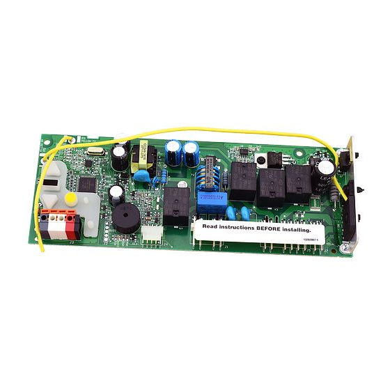
2
Remove the receiver logic board
2.1 Disconnect the wires from the quick-connect terminals (A).
Remove the receiver logic board end panel from the garage
door opener.
A
To insert or remove
the wires from the
terminal, push in the
tab with a
screwdriver tip.
NOTE: The products illustrated in the instructions are for reference. Your product may look different.
1.1 Remove the light lens by pulling the top
sides of the light lens and rotate the light
lens down. Squeeze the light lens clips to
remove lens from end panel.
2.2 Unplug the wire harnesses from the receiver logic
board. You may need needle-nosed pliers, to
remove the harnesses.
RECEIVER LOGIC BOARD REPLACEMENT
1.2 To maintain your warranty, place the
provided label over the existing label on
the end panel of the garage door opener.
2.3 Remove the receiver
1
Models 045DCT and 045DCT125
1.3 Disconnect electrical and battery power
(if applicable) to the garage door opener.
.
logic board from the
end panel by removing
the 2 screws and
releasing the 2 clips.
Clips
Screws
Publicidad
Tabla de contenido

Manuales relacionados para LiftMaster 045DCT


Resumen de contenidos para LiftMaster 045DCT
- Página 1 RECEIVER LOGIC BOARD REPLACEMENT Models 045DCT and 045DCT125 Installation Before you begin NOTE: The products illustrated in the instructions are for reference. Your product may look different. 1.1 Remove the light lens by pulling the top 1.2 To maintain your warranty, place the 1.3 Disconnect electrical and battery power...
- Página 2 Install new receiver logic board 3.2 Insert the antenna wires through 3.1 Connect the wire harnesses to the 3.3 Reinsert the wires. 3.4 Install the light lens by aligning with the holes in the end panel. Snap the new receiver logic board. When Door control wires: the hinges and snapping into place.
-
Página 3: Program The Travel
Adjustment Program the travel 1.1 Press and hold the Adjustment Button 1.2 Press and hold the UP Button until the 1.3 Once the door is in the desired until the UP Button begins to fl ash and/ door is in the desired UP position. UP position press and release the or a beep is heard. -
Página 4: Test The Safety Reversal System
Test the Safety Reversal System If the door stops and does not reverse on the 2.1 With the door fully open, place a 2.2 Press the remote control push button obstruction, increase the down travel (refer to 1-1/2 inch (3.8 cm) board (or a 2x4 laid to close the door. - Página 5 REMPLACEMENT DE LA CARTE LOGIQUE DU RÉCEPTEUR Modèles 045DCT et 045DCT125 Installation Avant de commencer REMARQUE : Les produits illustrés dans les instructions sont pour référence. Votre produit peut toutefois avoir l’air différent. AVERTISSEMENT AVERTISSEMENT 1.3 Déconnectez l’alimentation 1.1 Retirez la lentille en tirant les côtés 1.2 Pour conserver votre garantie, placez...
- Página 6 Installez le nouvelle carte logique du récepteur 3.2 Insérez les fi ls d’antenne à travers les 3.3 Réinsérez les fi ls. 3.4 Installez la lentille en l’alignant avec 3.1 Connectez les harnais de fi ls à la trous du panneau d’extrémité. nouvelle carte logique du récepteur.
-
Página 7: Programmation De La Course
Réglages AVERTISSEMENT Programmation de la course AVERTISSEMENT AVERTISSEMENT AVERTISSEMENT 1.1 Appuyer sur le bouton de réglage 1.2 Appuyer sur le bouton UP et le 1.3 Une fois que la porte est dans la et le maintenir enfoncé jusqu’à maintenir enfoncé jusqu’à ce que position d’ouverture désirée, appuyer ce que le bouton UP commence à... -
Página 8: Essai Du Système D'inversion De Sécurité
AVERTISSEMENT Essai du système d’inversion de sécurité AVERTISSEMENT AVERTISSEMENT AVERTISSEMENT Si la porte s’arrête et ne remonte pas en 2.1 La porte étant entièrement ouverte, 2.2 Appuyer sur le bouton-poussoir de raison de l’obstruction, augmenter la course placer une planche de 3,8 cm (1 1/2 po) la télécommande pour fermer la porte. -
Página 9: Desconecte Los Cables De Los Terminales De Conexión
REEMPLAZO DE LA TARJETA LÓGICA DEL RECEPTOR Modelos 045DCT y 045DCT125 Installation Antes de comenzar NOTA: Los productos ilustrados en las instrucciones son para su referencia. Su producto puede verse diferente. 1.2 A fi n de conservar su garantía, 1.3 Desconecte del abre-puertas de 1.1 Retire la lente de luz tirando de los... -
Página 10: Instale La Nueva Tarjeta Lógica Del Receptor
Instale la nueva tarjeta lógica del receptor 3.1 Conecte el hato de cables a la nueva 3.2 Inserte los cables de la antena a través 3.3 Vuelva a insertar los cables. 3.4 Instale la lente de luz alineándola de los orifi cios del panel posterior. tarjeta lógica del receptor. -
Página 11: Programación De La Carrera
Ajustes Programación de la carrera 1.1 Oprima y mantenga oprimido el 1.2 Oprima y mantenga oprimido el 1.3 Una vez que la puerta esté en la botón “Ajuste” hasta que el botón botón ARRIBA hasta que la puerta posición deseada, oprima y suelte el ARRIBA empiece a parpadear y/o se encuentre en la posición Botón “Ajuste”. -
Página 12: Prueba Del Sistema De Seguridad De Reversa
Prueba del sistema de seguridad de reversa Si la puerta se detiene y no retrocede al 2.1 Con la puerta completamente abierta, 2.2 Oprima el botón pulsador del control hacer contacto con la obstrucción, aumente coloque una tabla de 3,8 cm remoto para cerrar la puerta.