Publicidad
Enlaces rápidos
Publicidad

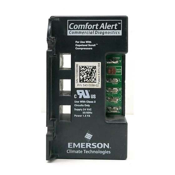
Resumen de contenidos para Emerson Confort Alert Diagnostic
- Página 1 User’s Manual Questions or Comments? Call 1-888-923-2323...
- Página 2 A flashing LED indicator communicates the ALERT code and guides the service technician more quickly and accurately to the root cause of a problem. The Comfort Alert module is also compatible with all Emerson branded thermostats of the 1F9X and 1F8X families that offer diagnostic “L” terminal connection. For better protection, the 1F9X/1F8X “CA”...
-
Página 3: Hardware Installation
Application, Benefits And Product Specifications 543-0010-00 Part Number: 543-0010-01 543-0012-00 543-0033-02 543-0032-00 (Service Number) (943-0010-00) (943-0012-00) (943-0033-00) (943-0010-01) A/C and Heat Pump: Heat Pump: Single A/C and Heat Pump: A/C: Single Stage Two Stage with Application Stage with Copeland Single Stage with with Copeland Scroll ®... - Página 4 Part Numbers: 543-0010-00, 943-0010-00, 543-0012-00, 943-0012-00 A. 1.81 in (46 mm) D. 3.15 in (80mm) B. 2.44 in (62 mm) E. 2.44 in (62 mm) C. 1.43 in (36 mm) Figure 2 Part Numbers: 543-0010-01, 943-0010-01 A. 1.81 in (46 mm) D.
- Página 5 Part Numbers: 543-0032-00, 943-0033-00, 543-0033-02 A. 1.85 in (47 mm) D. 4.40 in (112mm) B. 2.44 in (62 mm) E. 2.44 in (62 mm) C. 1.46 in (37 mm) Figure 4 Compressor Wire Routing (Figure 5) The scroll compressor’s run (R), common (C) and start (S) wires are routed through the holes in Comfort Alert marked “R,”...
- Página 6 Note: 24VAC power wiring is not required for 2 wire Comfort Alert, which is powered by the demand (Y terminal). Even if the 24VAC power supply is available it should not be connected. Refer to Figure 7. Thermostat Demand Wiring Comfort Alert requires a thermostat demand signal to operate properly.
- Página 7 Figure 7: Air Conditioning Schematic 543-0010-01, 943-0010-01 Solid Line shows field installed wiring. LPCO HTCO Dashed line shows thermostat demand wiring in system without HTCO, LPCO. HPCO Comfort Alert Diagnostics Module 543-0010-00 Indoor Unit Terminal Block Single Stage Indoor Thermostat Schematic Abbreviation Description HTCO High Temperature Cut Out Switch CC Compressor Contactor...
- Página 8 Figure 9: Air Conditioning or Heat Pump Schematic 543-0032-00 Solid Line shows field installed wiring. LPCO HTCO Dashed line shows thermostat demand wiring in system without HTCO, LPCO and Defrost. HPCO Comfort Alert Diagnostics Module 543-0032-00 Indoor Unit Terminal Block Single Stage Indoor Thermostat Schematic Abbreviation Description HTCO High Temperature Cut Out Switch...
- Página 9 L Terminal Wiring (Part Numbers 543-0032-00, 543-0033-02, 943-0033-00) The L connection is used to communicate Alert codes to compatible White-Rodgers ® thermostats. The L terminal of the thermostat should be connected directly to the Comfort Alert L terminal. On select White-Rodgers thermostats, an icon on the thermostat display will flash at the same rate as the Comfort Alert yellow Alert LED.
- Página 10 Interpreting The Diagnostic LEDs When an abnormal system condition occurs, the Comfort Alert module displays the appropriate ALERT and/or TRIP LED. The yellow ALERT LED will flash a number of times consecutively, pause and then repeat the process. To identify a Flash Code number, count the number of consecutive flashes.
- Página 11 LED Troubleshooting Information Status LED Status LED Description Status LED Troubleshooting Information Green “POWER” Module has power Supply voltage is present at module terminals 1.Compressor protector is open • Check for high head pressure • Check compressor supply voltage Thermostat demand 2.Outdoor unit power disconnect is open Red “TRIP”...
- Página 12 LED Troubleshooting Information Continued Status LED Status LED Description Status LED Troubleshooting Information 1. Thermostat demand signal is intermittent Short Cycling Yellow “ALERT” 2. Time delay relay or control board defective Compressor is Flash Code 3 3. If high pressure switch present go to Flash Code 2 running only briefly information 1.
- Página 13 NOTE: The correct Comfort Alert model must be used for the application (refer to the Application, Benefits and Product Specifications section on page 3). If the wrong model is installed, or Comfort alert is wired incorrectly, the ALERT Flash Codes for system faults may function incorrectly: Comfort Alert may indicate system faults that are not present or fail to indicate system faults that are present.
- Página 14 Patent 6, 615, 594 and Additional Patents Pending 2006ECT-54 R7 (06/09) Emerson, Copeland, Copeland Scroll, Comfort Alert. UltraTech and White Rodgers are the trademarks of Emerson Electric Co. or one of its affiliated companies. © 2006 Emerson Climate Technolgies, Inc. All rights reserved. Printed in the USA.


