Publicidad
Idiomas disponibles
Idiomas disponibles
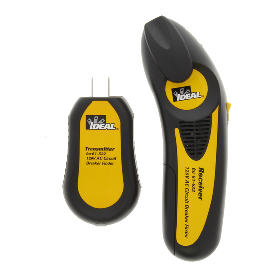
120V AC Circuit Breaker Finder
The IDEAL 61-532 is a 120V AC Circuit Breaker Finder that automatically identifies a circuit breaker/fuse protecting
a live branch circuit. It consists of a transmitter and a receiver. The Transmitter identifies the presence of power
via a red LED and sends a signal over the conductors when connected to an energized circuit. The receiver
reads the transmitter's signal and identifies the breaker/fuse energizing the circuit by illuminating a red LED
and emitting a continuous beep once it determines the breaker/fuse with the strongest signal.
WARNING
Arc Flash and Shock Hazard, Proper PPE Required. Follow all safety procedures, wear proper PPE in
accordance to NFPA 70E and follow the guidelines below and the instructions in this manual when
operating the circuit breaker finder. Failure to comply can result in serious injury or death.
• Use only as specified in this manual or protection provided can be compromised.
• Before using, visually inspect to ensure the cases are not cracked and the battery
cover is securely in place. Do not use if there appears to be any damage to the unit.
• Only experienced or technically competent consumers should use this equipment.
When in doubt, call an experienced electrician to make all necessary repairs or
installations.
• The equipment is intended for use by qualified electricians. Follow NFPA 70E
Standards for Electrical Safety in the Workplace when using this equipment.
• Do not use without the batteries correctly in place and the battery cover closed
and secured.
• Do not use if it operates incorrectly as protection may be compromised. When in doubt, have the unit serviced
only by qualified service personnel.
• Do not use the equipment around explosive gas, dust, or vapor, or during electrical storms, or in wet environments.
• Do not submerge or expose the meter to water and do no use if the meter has ever been exposed to water or other fluids
• Not for use in ANY patient care area where/when patient support equipment may be plugged into the same branch circuit.
• Voltages exceeding 30VAC or 60VDC pose a shock hazard so use caution.
• If used on a circuit controlled by a dimmer, turn the dimmer to the highest on position.
• Use extreme caution when working around bare conductors. Contact with the conductor could result in electric shock.
• Adhere to local and national safety codes. Personal Protective Equipment (PPE) must be used to prevent shock and arc blast injury where
hazardous live conductors are exposed.
• Before using the test leads (applies when using the TL-532A lead set), inspect carefully for damaged insulation, exposed metal or damaged
protective hoods. Do not use leads if they appear damaged.
• Use only approved test leads (TL-532A or equivalent). Do not use improvised connections that could present a safety hazard.
• Connect the common test lead before connecting the live test lead. When disconnecting test leads, disconnect the live test lead first.
• Do not apply more than the rated voltage.
• Do not work alone so that assistance can be rendered in an emergency.
•
Cancer and Reproductive Harm - www.P65Warnings.ca.gov
Locating A Circuit Breaker or Fuse:
1. Plug the transmitter into the receptacle.
2. Go to the circuit breaker panel box.
3. Turn the receiver on.
4. Place the flat surface of the tapered end of the receiver directly onto the circuit breaker or fuse as shown. (Figure 3)
If the receiver is held at any other angle, inaccurate readings may occur.
5. Slide the nose of the receiver along the outer edge of each row of breakers using a racetrack pattern as shown
(Figure 4). Note that the receiver will beep frequently as it measures the relative signal strength during the first pass.
6. Repeat step 5. On the second pass, the receiver will beep and the red LED will light, and the receiver will beep only
on the circuit breaker powering the transmitter.
7. Trip the breaker off and check that the LED on the transmitter in the outlet is off to confirm you have found the
correct breaker or fuse.
Locating a Circuit Breaker or Fuse Controlling an Incandescent Light Fixture
1. If the incandescent light fixture is controlled by a wall switch, make sure the wall switch is OFF.
2. Remove light bulb.
3. Install a Screw-in socket adapter (not included).
4. Plug the transmitter into the adapter.
5. Turn on the wall switch and follow the procedure described in Locating a Circuit Breaker or Fuse, steps 3 through 7.
Note: If used on a circuit controlled by a dimmer, turn the dimmer to the highest on position.
Transmitter
for 61-532
120V AC Circuit
Breaker Finder
WARNING
Arc Flash and Shock Hazard, Proper PPE
Required. Follow all safety procedures, wear
proper PPE in accordance to NFPA 70E.
Read and fully understand the instruction
manual prior to using this product. Failure to
comply can result in serious injury or death.
125VAC Max./0.6W
CIRCUIT
TESTER
810R
IDEAL INDUSTRIES, INC.
Sycamore, IL 60178 U.S.A.
LED
Power Switch
LED
Battery Compartment
61-532
Figure 3
Main
Breaker
1
11
2
12
3
13
4
14
5
15
6
16
7
17
8
18
9
19
10
20
Figure 4
Publicidad
Tabla de contenido

Manuales relacionados para Ideal 61-532


Resumen de contenidos para Ideal 61-532
- Página 1 120V AC Circuit Breaker Finder The IDEAL 61-532 is a 120V AC Circuit Breaker Finder that automatically identifies a circuit breaker/fuse protecting a live branch circuit. It consists of a transmitter and a receiver. The Transmitter identifies the presence of power via a red LED and sends a signal over the conductors when connected to an energized circuit.
-
Página 2: Interruptor De Alimentación
Buscador de Cortacircuitos de CA de 120V IDEAL 61-532 es un Buscador de Cortacircuitos de CA de 120V que identifica automáticamente un cortacircuitos/fusible protegiendo un circuito derivado en vivo. Consiste en un transmisor y un receptor. El transmisor identifica la presencia de energía a través de un LED rojo y envía una señal sobre los conductores cuando está... -
Página 3: Compartiment De Pile
#61-532 Détecteur de disjoncteur de 120 V C.A. L’IDEAL 61-532 est un détecteur de disjoncteur de 120 V C.A. 120V qui identifie automatiquement un disjoncteur/fusible protégeant un circuit de dérivation sous tension. Il se compose d’un émetteur et d’un récepteur. par l’intermédiaire d’une LED rouge et envoie un signal sur les conducteurs une fois relié... -
Página 4: Battery Replacement
This tester is warranted to the original purchaser against defects in material and workmanship for a period of two (2) years from date of purchase. With proof of purchase from an authorized IDEAL distributor, a defective tester will be repaired or replaced with the same product or a function- ally equivalent product, at the option of IDEAL INDUSTRIES, INC. -
Página 5: Especificaciones
Esta garantía constituye el único y exclusivo remedio del comprador y la responsabilidad exclusiva de IDEAL, y reemplaza cualquier otra garantía, y renuncia expresamente a todas las demás garantías, implícitas o legales en cuanto a la comercia- bilidad, idoneidad para el propósito vendido, descripción, productividad de calidad, o cualquier otro asunto. - Página 6 Cet appareil de contrôle est garanti à l’acheteur original contre tout vice de matériau ou de façon pendant une période de deux (2) ans à compter de la date d’achat. Avec la preuve d’achat délivrée par un distributeur IDEAL agréé, un appareil de contrôle défectueux sera, réparé ou remplacé avec le même produit ou un produit fonctionnellement équivalent, au choix d’IDEAL INDUSTRIES, INC., pendant la période de garantie dans la mesure ou le vice ou la défaillance...