Publicidad
Idiomas disponibles
Idiomas disponibles
Enlaces rápidos
PowPak
|
Installation
®
Dimming Module with 0 – 10 V
041457
Part of the Energi TriPak
Family
Rev. A
®
04/2014
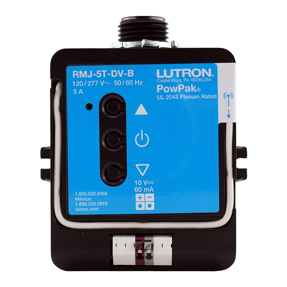
RMJ-5T-DV-B
120 / 277 V~ 50 / 60 Hz 5 A
URMJ-5T-DV-B
UL 2043 Plenum Rated
RMK-5T-DV-B
220 – 240 V~ 50 / 60 Hz 5 A
RMN-5T-DV-B
RMQ-5T-DV-B
RMM-5T-DV-B
0 – 10 V Control: 10 V- 60 mA
Compatible with ANSI E1.3 2001 (R2006), IEC 60929 Annex E
Important Notes: Please read before installing.
For installation by a qualified electrician in accordance with all
local and national electrical codes.
• Note: Use copper conductors only.
• Check to see that the device type and rating is suitable for the
application.
• DO NOT install if product has any visible damage.
• If moisture or condensation is evident, allow the product to dry
completely before installation.
• Operate between 0 °C and 40 °C, ambient.
• 0% to 90% humidity, non-condensing.
• For indoor use only.
PowPak
Dimming Module
®
Install in center of room
to maximize RF coverage.
Radio Powr Savr
TM
Occupancy Sensor
30 ft (9 m) max
PowPak
®
Dimming
Module
Pico
®
Wireless Control
39 ft (12 m)
All Wireless
Transmitters
must be
installed within
30 ft (9 m) of the
PowPak
Dimming Module.
®
Default Functionality
Occupancy Sensors
Occupied: All lights 100%.
Unoccupied: All lights off.
Daylight Sensor
All lights dim in response to daylight.
Link
Cal.
Test
Wireless Controls
On
All lights 100%
Favorite All lights 50%
Off
All lights off
PowPak
|
Programming
®
ALL PROGRAMMING IS OPTIONAL
Programming is not required for default functionality
• Set a favorite light level
• Set high-end and low-end trim for all fixtures
• Set occupancy levels
• Set minimum light level for all fixtures
Please consult individual component installation and
programming guides for more details.
FCC Information (RMJ- and URMJ- only)
This device complies with part 15 of the FCC Rules and Industry Canada license-exempt
RSS standard(s). Operation is subject to the following two conditions: (1) This device
may not cause interference, and (2) this device must accept any interference, including
interference that may cause undesired operation. Modifications not expressly approved by
Lutron Electronics Co., Inc. could void the user's authority to operate this equipment.
NOTE: This equipment has been tested and found to comply with the limits for a Class B
digital device, pursuant to part 15 of the FCC Rules. These limits are designed to provide
reasonable protection against harmful interference in a residential installation. This equipment
generates, uses and can radiate radio frequency energy and, if not installed and used in
accordance with the instructions, may cause harmful interference to radio communications.
However, there is no guarantee that interference will not occur in a particular installation. If
this equipment does cause harmful interference to radio or television reception, which can
be determined by turning the equipment off and on, the user is encouraged to try to correct
the interference by one or more of the following measures:
• Re-orient or relocate the receiving antenna.
• Increase the separation between the equipment and receiver.
• Connect the equipment into an outlet on a circuit different from that to which the receiver
is connected.
Lutron Electronics hereby declares that RMK-5T-DV-B is in compliance with the
essential requirements and other relevant provisions of Directive 1999/5/EC. A
copy of the DoC can be obtained by writing to Lutron Electronics Co., Inc. 7200
Suter Road, Coopersburg, PA 18036 USA
Warranty: For warranty information, please see
the Warranty enclosed with the product, or visit
www.lutron.com/TechnicalDocumentLibrary/369-119_Wallbox_Warranty.pdf
Although every attempt is made to ensure that catalogue information is
accurate and up-to-date, please check with Lutron EA before specifying or
purchasing this equipment to confirm availability, exact specifications, and
suitability for your application.
Lutron, Pico, PowPak, Energi TriPak, and
Required Components
For each system, ensure that you have:
One PowPak
Dimming Module
At least one Wireless Transmitter
®
Load Status LED
Raise
Toggle
+
Lower
PowPak
Dimming Module with 0 – 10 V
Radio Powr Savr
®
(1 maximum)
(6 maximum)
Start Here
1
Mount, Wire, and Install 0 – 10 V
Devices and Lighting Fixtures
Consult third-party device installation guide
WARNING! Shock Hazard. May result in serious injury or death.
Turn off power at circuit breaker before installing the unit.
A
Connect mains wiring (switched hot, neutral) to each fixture.
B
Connect 0 – 10 V control (+ and – ) to each fixture.
Green/Yellow
Fixture Earth
Neutral
NEU
Switched Hot/Live
HOT
+
Violet
+
–
–
Gray
Sample ballast shown
To additional 0 – 10 V fixtures
3
Associate Wireless Transmitters to PowPak
Dimming Module
Before beginning this step, make sure that
there are no other PowPak
modules being set
®
up within the same building. It is possible that
wireless transmitters from other systems can
be incorrectly associated to this module.
A
On PowPak
Dimming Module, hold Toggle
®
button " " for 6 seconds until lights flash.
The Load Status LED will begin flashing twice
per second.
B
Hold the indicated button on each transmitter
for 6 seconds. Lights will flash to show that
wireless transmitters have been associated.
Link
Test
C
On PowPak
Dimming Module, hold Toggle button " " for 6 seconds to save
®
association. Lights will flash and LED will quickly blink for 2 seconds.
6
7
Set a Favorite Light Level
Set Low-End and High-End Trim
For Pico
Wireless Controls with a Favorite
For best results, minimize the amount of sunlight entering the
®
Button.
room before performing the following procedures.
A
Adjust lights to desired level:
Low-End Trim
Use Raise button "
" or Lower button "
"
A
Enter low-end trim adjustment mode:
on Pico
Wireless Control.
®
Press and hold Lower button " " for 12 seconds.
Lights will flash high-low-high and LED will begin flashing.
B
Adjust the low-end trim:
Use Raise button " " and Lower button
Raise
Lower
" " to adjust and set the lights to the
desired low-end (1 to 45%).
C
Save the low-end trim:
Press and hold Toggle button " " for
6 seconds to save setting.
LED will begin flashing and then turn
B
Save favorite level:
solid to indicate new level has been
Press and hold Favorite button for 6 seconds.
saved.
High-End Trim
D
Enter high-end trim adjustment mode:
Press and hold Raise button " " for
Favorite
12 seconds.
Lights will flash high-low-high and LED
will flash.
E
Adjust the high-end trim:
Reset Factory Defaults
Use Raise button " " and Lower button
" " to adjust and set the lights to the
Note: In some instances, it may be necessary
desired high-end (55 to 100%).
to reset the PowPak
Dimming Module and
®
F
Save the high-end trim:
connected devices back to factory default
Press and hold Toggle button " " for
settings. Before beginning, make sure that all
6 seconds to save setting.
devices are connected and powered.
LED will begin flashing and then turn
A
Triple-tap the Toggle button " " on the
solid to indicate new level has been
PowPak
Dimming Module and hold until the
®
saved.
LED begins to flash slowly; release button.
B
Within 3 seconds of the start of flashing,
triple-tap the same button again and the LEDs
will flash rapidly indicating that the unit has been
reset to factory defaults.
Note: Any associations or programming
previously set up with the PowPak
will be
®
erased and will need to be re-programmed.
Occupancy/Vacancy Sensor
Pico
Wireless Control
TM
®
(9 maximum)
2
Install PowPak
Dimming Module
®
Suggested Installation Location: Center of room to ensure
proper RF coverage of area.
A
PowPak
Dimming Module can be installed in a junction box
®
or marshalling box using the conduit nut (provided) or with
mounting screws (not provided). Please consult local and
national electric codes for proper installation.
If installing unit inside a junction box,
please see Application Note #423 at
http://www.lutron.com/TechnicalDocumentLibrary/048423.pdf
B
Once installed, energize the PowPak
Dimming Module.
®
C
Use the Toggle button " " to toggle between high-end and
OFF to verify ballast wiring.
D
Use the Raise " " and Lower " " buttons to verify control
wiring.
4
Install Wireless
®
Transmitters
Note: Please consult individual component
installation guides for information.
Link
Test
5
Calibrate Daylight Sensor
Daylight Sensor will control all wired fixtures equally.
A
Set lights in room to desired light level.
B
Press and hold "Cal." for
6 seconds.
C
Exit room for 5 minutes to
complete calibration.
Note: When calibration has
completed, all lights will flash
Link
and begin daylighting.
Multiple Daylight Rows
(OPTIONAL)
For every row of daylighting a separate PowPak
Dimming Module must be used. For detailed setup
refer to the tuning section of the Radio Powr Savr
Daylight Sensor installation guide.
• Select the PowPak
Dimming Module that you want
®
to adjust by pressing the toggle button.
Notes
Depending on the fixture
manufacturer or load, low-end
and high-end trim may need to be
adjusted.
• Trim low-end to ensure a stable
light level because some loads will
flicker or drop out if trimmed too
low.
• Be sure that you can turn on the
lights to the low-end trim level
without any abnormal operation.
• The factory default high-end trim
will normally be sufficient for most
applications. Trim as desired.
Troubleshooting
Ballasts cannot be controlled locally from
PowPak
Dimming Module.
®
Lights do not dim as expected.
Lights do not respond to Wireless
Transmitter(s).
Lights are unstable at low-end or flash/
flicker at turn-on or turn-off.
Wireless Transmitter(s) cannot be
associated to PowPak
Dimming
®
Module.
At least one 0 – 10 V Fluorescent Ballast or LED Driver
Consult third-party 0 – 10 V fixtures installation guide for fixture-specific wiring.
+
Link
Cal.
Test
Radio Powr Savr
Daylight Sensor
60 mA maximum for the control lines. Switches up to 5 A total. May be
TM
(1 maximum)
pre-installed in light fixture.
Wiring for Model Numbers:
RMJ-5T-DV-B
120 / 277 V~
URMJ-5T-DV-B 120 / 277 V~
Hot (Black)
RMQ-5T-DV-B
220 – 240 V~
RMM-5T-DV-B
220 – 240 V~
Neutral
Wiring for Model Numbers:
RMK-5T-DV-B
220 – 240 V~
RMK- RMN-
RMN-5T-DV-B
220 – 240 V~
Line (Brown) (Red)
Neutral
Daylight Override
Lowering the light level from an
associated Pico
wireless control will
®
lower the daylight level. Raising the
light level from a Pico
wireless control
®
will temporarily override daylighting for
2 hours.*
Daylight Re-Enable
Daylighting will return to the calibrated
Cal.
level when one of the following occurs:
Test
Wiring a Lever-Operated Connector (RMK-)
• OFF has been pressed on a Pico
®
When wiring lever-operated
wireless control.
connectors (5 supplied), use
• All associated Occupancy Sensors
®
14 to 12 AWG (2.5 to 4.0 mm
have reported unoccupied.
diameter solid or stranded
TM
copper wire. For Model Number
RMN-5T-DV-B, use twist-on wire
* Each time a daylighting override
occurs, the two-hour timer is reset.
connectors (3 supplied).
8
Set Minimum Light Level
Certain applications (e.g., hallways), may
require that the lights never turn off. For
these areas, activate Minimum Light Level
mode.
A
Enter minimum light level adjustment mode:
Press and hold Toggle button " " and
Lower button " " for 12 seconds. Lights
will flash high-low-high and LED will begin
flashing.
If lights stop flashing and go to high-end,
the minimum light level is set to OFF
(default).
If lights stop flashing and go to low-end,
the minimum light level is ON and set to
low-end.
B
Change the minimum light level:
Press Raise button " " to set minimum
light level to low-end.
Press Lower button " " to set minimum
light level to OFF.
C
Save the minimum light level:
Press and hold Toggle button " " for
6 seconds. LED will quickly flash to indicate
that new level has been saved.
• Ensure that the breaker(s) to the PowPak
Dimming Module are energized.
®
• Ensure that the PowPak
Dimming Module switched hot lead is wired to the lighting fixture(s).
®
• Ensure that the PowPak
Dimming Module 0 –10 V control lines are wired to the lighting fixture(s).
®
Reset to factory defaults.
• Ensure that 0 –10 V control lines are wired properly.
• Ensure that fixture does not require an inverted signal (10 – 0 V control).
• Ensure that the breaker(s) to the PowPak
Dimming Module and ballasts are energized.
®
• Ensure that Wireless Transmitters are associated to the PowPak
Reset to factory defaults.
• Adjust low-end trim.
• The maximum number of Wireless Transmitters have been associated to the PowPak
remove a previously set up Wireless Transmitter, tap a Wireless Transmitter button three times; on the third tap hold
for three seconds and then tap three more times.
Junction Box
Switched Hot (Red)
To Fixtures
Neutral (White)
1/2 in (21 mm) Knockout Opening
Conduit Nut
–
0 – 10 V to Fixtures*
+
2
* Use 18 to 16 AWG (0.75 to 1.5 mm
) solid wire only
Junction Box
RMK- RMN-
Switched Line (Black) (Yellow)
(Blue) (Black) To Fixtures
Neutral
– (Gray)
0 – 10 V to Fixtures
+ (Violet)
21 mm Knockout Opening
Conduit Nut
3
2
)
1
2
10 mm
9
Set Occupancy Light Levels
Note: Unoccupied light level is always the minimum light
level and cannot be adjusted.
A
Set desired occupancy light levels:
Use Raise/Lower buttons " / " on the PowPak
®
Dimming Module or Raise/Lower buttons "
/
" on all
associated Pico
Wireless Controls.
®
B
Save occupancy light levels:
Press and hold Test button for
6 seconds on any associated
Radio Powr Savr
Occupancy
TM
Sensor without a Lights On
button. Release when Sensor
lens starts to flash.
Or, press and hold Lights
On button for 6 seconds on
any associated Radio Powr
Savr
Occupancy Sensor.
TM
Release when Sensor lens
starts to flash.
www.lutron.com
Dimming Module.
®
Dimming Module. To
®
Publicidad

Manuales relacionados para Lutron PowPak RMJ-5T-DV-B


Resumen de contenidos para Lutron PowPak RMJ-5T-DV-B
- Página 1 Directive 1999/5/EC. A will normally be sufficient for most Lights will flash high-low-high and LED copy of the DoC can be obtained by writing to Lutron Electronics Co., Inc. 7200 6 seconds. LED will quickly flash to indicate applications. Trim as desired.
- Página 2 Composants requis PowPak Installation Assistance technique | 1.800.523.9466 É-U, Canada, et les Caraïbes | +44.(0)20.7702.0657 Europe | +1.610.282.3800 Autres | www.lutron.com ® Pour chaque système, assurez-vous d’avoir : Module de gradation de 0 – 10 V Un module de gradation PowPak Au moins un transmetteur sans fil...
-
Página 3: Instalación
Directiva 1999/5/ nuevo nivel ha sido guardado. EC. Se puede solicitar una copia por escrito a: Lutron Electronics Co., Inc. Ajuste el extremo alto: 7200 Suter Road, Coopersburg, PA 18036 E.U.A. -
Página 4: Fehlersuche Und -Behebung
Erforderliche Komponenten PowPak Installation Technische Unterstützung | 1.800.523.9466 USA, Kanada, Karibik | +44.(0)20.7702.0657 Europa | +1.610.282.3800 Sonstige | www.lutron.com ® Vergewissern Sie sich, dass für jedes System folgende Komponenten vorliegen: Dimmermodul mit 0-10 V Ein PowPak Dimmermodul Mindestens ein drahtloser Sender Mindestens ein 0-10-V-Leuchtstofflampen-Vorschaltgerät oder –... - Página 5 Componenti necessari PowPak Installazione Assistenza Tecnica | 1.800.523.9466 USA, Canada, e Caraibi | +44.(0)20.7702.0657 Europa | +1.610.282.3800 Altrove | www.lutron.com ® Per ogni impianto, assicurarsi di avere: Modulo di dimmeraggio con 0 – 10 V Modulo di dimmeraggio PowPak Almeno una Trasmittente Wireless Almeno un reattore per lampade fluorescenti 0 –...
- Página 6 Componentes Requeridos PowPak Instalação Assistência Técnica | 1.800.523.9466 EUA, Canadá e Caraíbas | +44.(0)20.7702.0657 Europa | +1.610.282.3800 Outros | www.lutron.com ® Certificar-se de que possui o seguinte para cada sistema: Módulo de Regulação de Fluxo Luminoso com 0 – 10 V Um Módulo de Regulação de Fluxo...
- Página 7 Benodigde onderdelen PowPak Installatie Technische Ondersteuningsdienst | 1.800.523.9466 VS, Canada en de Caraïben | +44.(0)20.7702.0657 Europa | +1.610.282.3800 Overig | www.lutron.com ® Voor elk systeem heeft u het volgende nodig: Dimmodule met 0 – 10 V Een PowPak dimmodule Tenminste één draadloze zender Tenminste één 0 –...
- Página 8 RMK-5T-DV-B 1999/5/EC Lutron Electronics Co., Inc. 7200 Suter Road, Coopersburg, PA 18036 USA www.lutron.com/TechnicalDocumentLibrary/369-119_Wallbox_Warranty.pdf 100% Lutron, Pico, PowPak, Energi TriPak, Clear Connect, Lutron Electronics Co., Inc. Radio Powr Savr Lutron Electronics Co., Inc. www.lutron.com ©2013 Lutron Electronics Co., Inc. PowPak PowPak ®...