Publicidad
Idiomas disponibles
Idiomas disponibles
Vive PowPak
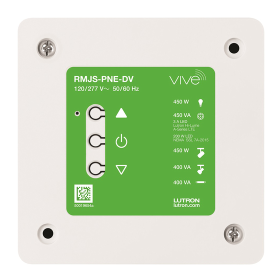
Phase Select Dimming Module
Emergency Phase Select Dimming Module
Part of the Vive Family
RMJS-PNE-DV
120 / 277 V~ 50 / 60 Hz
RMJS-PNE-DV-EM
450 W Incandescent / Halogen
450 VA LED (reverse-phase)
3 A Lutron Hi-lume 1% 2-wire LED driver (13 drivers max)
200 W LED NEMA SSL 7A-2015
450 W ELV
400 VA MLV
400 VA Fluorescent
0 W minimum load
Important Notes: Please read before installing.
For installation by a qualified electrician in accordance with all local and national electrical codes.
• Note: Use copper conductors only.
• Check to see that the device type and rating is suitable for the application.
• DO NOT install if product has any visible damage.
• If moisture or condensation is evident, allow the product to dry completely before installation.
• Operate between 0 °C and 40 °C (32 °F and 104 °F) ambient.
• 0% to 90% humidity, non-condensing.
• For indoor use only.
• For spec submittal, see http://www.lutron.com/TechnicalDocumentLibrary/3691150.pdf
• For application note, see http://www.lutron.com/TechnicalDocumentLibrary/048781.pdf
• Operation of a low-voltage circuit with removed or inoperative lamps may result in transformer overheating
and premature failure. Lutron strongly recommends the following:
a. Do not operate low-voltage circuits without operative lamps in place.
b. Replace burned-out lamps as quickly as possible.
c. Use transformers that incorporate thermal protection or fused transformer primary windings to prevent
transformer failure due to overcurrent.
IMPORTANT SAFEGUARDS
When using electrical equipment, basic safety precautions should always be
followed including the following:
READ AND FOLLOW ALL SAFETY
INSTRUCTIONS
• Do not use outdoors.
• Do not mount near gas or electric heaters.
• Equipment should be mounted in locations and at heights where it will not be
subjected to tampering by unauthorized personnel.
• The use of accessory equipment not recommended by the manufacturer may
cause an unsafe condition.
• Do not use this equipment for other than its intended use.
SAVE THESE INSTRUCTIONS
Phase Select PowPak
Install in center of room to
maximize RF coverage.
Radio Powr Savr
Occupancy
Sensor
PowPak
30 ft
RMJS-PNE-DV
120 / 277 V~ 50 / 60 Hz
module
(9 m) max
lutron.com
50019498a
Pico
Remote
Control
40 ft (12 m)
All Wireless Transmitters
must be installed within
30 ft (9 m) of the
PowPak module.
Default Functionality
Occupancy Sensors
Occupied: All lights 100%.
Unoccupied: All lights off.
Daylight Sensor
All lights dim in response to daylight.
Link
Cal.
Test
Wireless Controls
On
All lights 100%
Favorite All lights 50%
All lights off
Off
Lutron Electronics Co., Inc. 7200 Suter Road
Coopersburg, PA 18036-1299 USA
System Components
PowPak module
Wireless Transmitters
Indicator LED
041808
Rev. A
Raise
04/2021
RMJS-PNE-DV
120 / 277 V~ 50 / 60 Hz
Toggle
Lower
lutron.com
50019498a
Radio Powr Savr
Occupancy / Vacancy Sensor
(10 maximum per PowPak module)
Start Here
Mount, Wire, and Install Phase Dimmable
1
Devices and Lighting Fixtures
Consult third-party device installation guide
WARNING! Shock Hazard. May result in serious injury or death. Turn off power at circuit
breaker before installing the unit.
NOTE: Output must NOT be used to control receptacles. Output must be directly connected to the load.
Output breakers or switches must not be used.
Locate PowPak Module
2
Suggested Installation Location: Center of room
to ensure proper RF coverage of area. For optimal
RF performance: PowPak module must not be fully
enclosed in metal. No metal should exist anywhere
within 200 mm (8 in) in front of the front plate of the
PowPak module. Mount a minimum of 0.6 m (2 ft)
away from the controlled fixture. Ensure the junction
box is well grounded (preferably via a metal conduit
between the controlled fixture and the PowPak module
junction box).
A
PowPak module must be installed in a metal 101.6 mm x
101.6 mm (4 in x 4 in) junction box (minimum depth 54 mm
(2.125 in) with mounting screws (provided). Please consult local
and national electric codes for proper installation. NOTE: Adding
an extension ring is recommended for junction box depth
extension. See 048781 for additional options.
Install PowPak Module
3
A
Connect the bare copper wire from the junction box to the green ground
screw. Next, connect the power wires to the appropriate power and
load connections.
B
Once installed, energize the PowPak module.
C
Use the Toggle button " u " to toggle between high-end and OFF to
verify ballasts or LED drivers wiring.
D
Use the Raise "▲" and Lower "
" buttons to verify control wiring.
Wire Connector Information
1/2 in (13 mm):
(1-3) 10 AWG (4.0 mm
2
)
10, 12, & 14 AWG
(1-3) 12 AWG (2.5 mm
2
)
Red
Red
13 mm (1/2 in):
(1-3) 4.0 mm
2
(10 AWG)
(4.0, 2.5, &
(1-3) 14 AWG (1.5 mm
)
2
4.0, 2.5, & 1.5 mm
2
(1-3) 2.5 mm
2
(12 AWG)
1.5 mm
2
)
(1-2) 10 AWG & (1) 12 AWG (4.0 & 2.5 mm
2
)
(10, 12, & 14 AWG)
(1-3) 1.5 mm
(14 AWG)
2
(1-2) 10 AWG & (1) 14 AWG (4.0 & 1.5 mm
2
)
5/8 in (16 mm):
(1-2) 4.0 mm
& (1) 2.5 mm
2
16 & 18 AWG
(1-2) 12 AWG & (1) 14 AWG (2.5 & 1.5 mm
2
)
16 mm (5/8 in):
(1-2) 4.0 mm
2
& (1) 1.5 mm
(1-2) 10 AWG & (1) 16 AWG (4.0 & 1.0 mm
)
(1.0 & 0.75 mm
2
)
2
1.0 & 0.75 mm
2
(1-2) 2.5 mm
2
& (1) 1.5 mm
(1-2) 12 AWG & (1) 16 AWG (2.5 & 1.0 mm
)
2
(16 & 18 AWG)
(1-2) 4.0 mm
2
& (1) 1.0 mm
(1-2) 14 AWG & (1) 16 AWG (1.5 & 1.0 mm
2
)
(1-2) 2.5 mm
& (1) 1.0 mm
2
(1-2) 10 AWG & (1) 18 AWG (4.0 & 0.75 mm
(1-2) 1.5 mm
2
& (1) 1.0 mm
(1-2) 12 AWG & (1) 18 AWG (2.5 & 0.75 mm
(1-2) 4.0 mm
2
& (1) 0.75 mm
(1-2) 14 AWG & (1) 18 AWG (1.5 & 0.75 mm
(1-2) 2.5 mm
2
& (1) 0.75 mm
(1-2) 1.5 mm
& (1) 0.75 mm
2
3/8 in (10 mm):
(1-3) 12 AWG (2.5 mm
2
)
12 & 14 AWG
(2-3) 14 AWG (1.5 mm
2
)
Yellow
(2.5 & 1.5 mm
2
)
(1-2) 12 AWG & (1) 14 AWG (2.5 & 1.5 mm
2
Troubleshooting
(1-2) 12 AWG & (1) 16 AWG (2.5 & 1.0 mm
2
7/16 in (11 mm):
(1-2) 14 AWG & (1) 16 AWG (1.5 & 1.0 mm
2
16 & 18 AWG
(1-2) 12 AWG & (1) 18 AWG (2.5 & 0.75 mm
(1.0 & 0.75 mm
2
)
(1-2) 14 AWG & (1) 18 AWG (1.5 & 0.75 mm
Issue
Fixtures cannot be controlled locally from PowPak module.
Lights do not dim as expected.
Lights do not respond to Wireless Transmitter(s) (Pico remotes and RPS sensors).
Lights are unstable at low-end (or high-end) or flash / flicker at turn-on or turn-off.
Wireless Transmitter(s) (Pico remotes or RPS sensors) cannot be associated to PowPak module.
Pico Remote Control
Radio Powr Savr
Daylight Sensor
(10 maximum per
PowPak module)
(1 maximum per PowPak module)
4
200 mm
200 mm
(8 in))
(8 in)
RMJS-PNE-DV
120 / 277 V~ 50 / 60 Hz
Keep metal
200 mm
200 mm
200 mm
at least
200 mm
(8 in)
(8 in)
(8 in)
(8 in) away
A
lutron.com
50019498a
B
3.94
200 mm
200 mm
(100.1)
(8 in)
(8 in)
C
2.82
1.25
(71.6)
(31.8)
Line / Hot (Black)
Neutral
(10 & 12 AWG)
2
2
(10 & 14 AWG)
2
(12 & 14 AWG)
2
(10 & 16 AWG)
(12 & 16 AWG)
2
2
)
2
(14 & 16 AWG)
2
)
2
(10 & 18 AWG)
)
2
2
(12 & 18 AWG)
(14 & 18 AWG)
2
)
)
)
2
)
)
Solution
2
• Ensure that the breaker(s) to the PowPak module are energized.
• Ensure that the PowPak module dimmed hot lead is wired to the lighting fixture(s). (Ensure that line / hot and dimmed hot leads are not swapped.)
• PowPak module may be in emergency mode. The indicator LED will flash On and Off at 2 second intervals while in emergency mode.
Reset PowPak module to factory defaults. See www.lutron.com/vivevideos
• Ensure that dimmed hot lead is wired properly. (Ensure that line / hot and dimmed line / hot leads are not swapped.)
• PowPak module may be in emergency mode. The indicator LED will flash On and Off at 2 second intervals while in emergency mode.
• Ensure that the breaker(s) to the PowPak module and any connected ballasts or LED drivers are energized.
• Ensure that Wireless Transmitters are associated to the PowPak module.
Reset PowPak module to factory defaults. See www.lutron.com/vivevideos
• Adjust low-end (or high-end) trim.
• The maximum number of Wireless Transmitters have been associated to the PowPak module. To remove a previously set up Wireless Transmitter. See www.lutron.
com/vivevideos
Customer Assistance
At least one phase dimmable lighting load (incandescent, halogen, LED, fluorescent, ELV, or MLV)
Consult third-party fixtures installation guide for fixture-specific wiring.
Link
Cal.
Test
Vive Hub
Note: All drivers and ballasts used with Vive wireless controls must comply with the
limits pursuant to CAN ICES-005 and the FCC rules.
Phase Selection
Most loads are expected to use the default setting of reverse-phase, however some require forward-phase for proper functionality.
Load Type
Phase
Incandescent / Halogen
Reverse
LED
NEMA SSL 7A-2015
Forward
Lutron Hi-lume 1% 2-wire LED driver
Forward
Other LED drivers and self-ballasted lamps
Reverse
ELV
Reverse
MLV
Forward
Fluorescent
Forward
Enter Phase Selection mode. Press and hold Raise"
" & Lower "
" buttons for 12 seconds. Indicator LED will flash and load will fade to OFF.
Pressing the Raise button "
" sets the current phase to forward-phase, and pressing the Lower button "
Indicator LED Feedback:
(Reverse-phase): Flashes 1 time with a 1 second interval and then turns OFF for 2 seconds
(Forward-phase): Flashes 2 times with a 1 second interval and then turns OFF for 1 second
Press and hold the Toggle button for 6 seconds. Indicator LED will flash for 5 seconds. Load will fade to full ON.
Note: RMJS-PNE-DV-EM requires the use of an automatic transfer switch to change from normal to emergency power. Refer to
048628 for wiring diagrams on www.lutron.com
If installing an emergency PowPak module and the wiring needs to be verified, follow "Reset Factory Defaults" procedure to exit
emergency mode.
Junction Box
Please note that any programming will be lost and will have to be reprogrammed. Only perform this step during initial installation
and wiring verification.
Note: For periodic testing and maintanance of emergency systems, use a toggle switch or breaker to ensure proper operation.
Dimmed Line / Hot (Red)
Refer to App Note # 781 (P/N 048781) on www.lutron.com for procedure.
Note: Momentary power outages can envoke emergency mode on the PowPak module. SeeTroubleshooting section for details.
Neutral (White)
To Fixtures
Reset Factory Defaults
Ground (Green screw)
Note: In some instances, it may be necessary to reset the PowPak module and
connected devices back to factory default settings. Before beginning, make sure that
all devices are connected and powered.
RMJS-PNE-DV
120 / 277 V~ 50 / 60 Hz
A Triple-tap the Toggle button " u " on the PowPak module and hold until the LED begins
to flash slowly; release button.
B Within 3 seconds of the start of flashing, triple-tap the same button again and the
LEDs will flash rapidly indicating that the unit has been reset to factory defaults.
lutron.com
50019498a
Note: Any associations or programming previously set up with the PowPak module
will be erased and will need to be re-programmed.
www.lutron.com/support
www.lutron.com/support
" sets the current phase to reverse-phase.
Note: For more
troubleshooting help please
scan QR code below.
See page 2 for Programming
Publicidad
Tabla de contenido

Manuales relacionados para Lutron Vive PowPak RMJS-PNE-DV


Resumen de contenidos para Lutron Vive PowPak RMJS-PNE-DV
- Página 1 • Adjust low-end (or high-end) trim. Favorite All lights 50% • The maximum number of Wireless Transmitters have been associated to the PowPak module. To remove a previously set up Wireless Transmitter. See www.lutron. All lights off Wireless Transmitter(s) (Pico remotes or RPS sensors) cannot be associated to PowPak module.
-
Página 2: Error Codes
Lutron, PowPak, Pico, Hi-lume, Radio Powr Savr, and Vive are trademarks or registered trademarks of Lutron Electronics Co., Inc. in the US and/or other countries. Safari is a trademark of Apple Inc., registered in the U.S. and other countries. -
Página 3: Mesures De Précaution Importantes
Remarque : RMJS-PNE-DV-EM requiert l’emploi d’un commutateur de transfert automatique pour le passage de l’alimentation normale à Installer le module PowPak l’alimentation d’urgence. Se reporter à 048628 pour les schémas de câblage sur le www.lutron.com PowPak à sélection Si la vérification du câblage est requise lors de l’installation d’un module PowPak d’urgence; suivre la procédure « Rétablir les paramètres de phase d’usine par défaut »... -
Página 4: Codes D'erreur
Lutron, PowPak, Pico, Hi-lume, Radio Powr Savr et Vive sont des marques de commerce ou marques déposées de Lutron Electronics Co., Inc. aux É.-U. et/ou dans d’autres pays. Safari est une marque de commerce de Apple Inc., déposée aux É.-U. -
Página 5: Salvaguardas Importantes
Nota: Para las pruebas periódicas y el mantenimiento de los sistemas de emergencia, utilizar un interruptor de alternancia o un disyuntor Una vez instalado, energizar el módulo PowPak. para garantizar el funcionamiento correcto. El procedimiento se puede ver en la nota de aplicación n.º 781 (N/P 048781) en www.lutron.com. Línea/vivo atenuado (rojo) Módulo... -
Página 6: Códigos De Error
Lutron, PowPak, Pico, Hi-lume, Radio Powr Savr y Vive son marcas comerciales o registradas de Lutron Electronics Co., Inc. en E.U.A. y/u otros países. Safari es una marca registrada de Apple Inc., registrada en E.U.A. y en otros países. Los demás...