Tabla de contenido
Publicidad
Idiomas disponibles
Idiomas disponibles
Enlaces rápidos
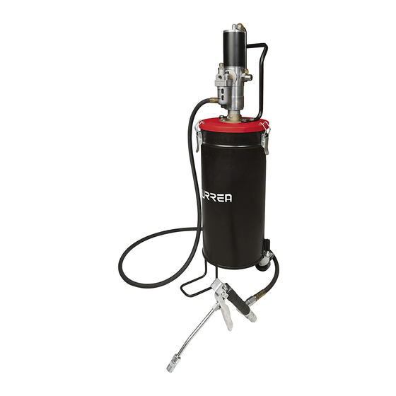
Bomba de Grasa Neumática
Manual de Usuario y Garantía.
User's Manual and Warranty.
ATENCIÓN: Lea, entienda y siga las instrucciones de seguridad contenidas en este
manual, antes de operar esta herramienta.
WARNING: Read, understand and follow the safety rules in this manual, before operating this tool.
Air Operated Grease Pump
23628
Publicidad
Tabla de contenido

Resumen de contenidos para Urrea 23628
- Página 1 Bomba de Grasa Neumática Air Operated Grease Pump 23628 Manual de Usuario y Garantía. User’s Manual and Warranty. ATENCIÓN: Lea, entienda y siga las instrucciones de seguridad contenidas en este manual, antes de operar esta herramienta. WARNING: Read, understand and follow the safety rules in this manual, before operating this tool.
-
Página 2: Tabla De Contenido
E S P A Ñ O L E N G L I S H CONTENIDO CONTENT Normas generales de seguridad General safety rules Características Features Instrucciones de operación Operation instructions Mantenimiento Maintenance Solucionador de problemas Troubleshooting Especificaciones técnicas Technical data Despiece de partes Spare parts Garantía... -
Página 3: Normas Generales De Seguridad
E S P A Ñ O L • M a nua l de U su a ri o NORMAS GENERALES DE SEGURIDAD CARACTERÍSTICAS ADVERTENCIA: Lea todas las advertencias de CONOZCA SU HERRAMIENTA seguridad y todas las instrucciones. La omisión de Antes de intentar usar este producto, familiarícese alguna de las advertencias e instrucciones que se con todas sus características de operación y reque-... -
Página 4: Instrucciones De Operación
de la grasa saliente a la presión del aire entrante. El cierre de la válvula de control de grasa apaga Cuando la relación de presión es 50:1, logramos el motor de aire y la bomba deja de dispensar la una presión de salida de la grasa de hasta 7500 PSI grasa. -
Página 5: Funcionamiento De La Bomba
E S P A Ñ O L • M a nua l de U su a ri o Utilice sellador de roscas en todas las conexiones • Tenga cuidado al montar anillos y sellos. Siem- pre lubrique con aceite o grasa antes del montaje. para asegurarse de tener un trabajo a prueba de Nunca deben ser roscados sobre bordes afilados al fugas. -
Página 6: Solucionador De Problemas
· Al montar empujadores de ajuste (15) , la cubier- queñas como ajuste para asegurar el mejor en- ta de la entrada libre (32) y asegurar la correcta samble. instalación de Pusher Botones (19). · El lado cónico (39) debe estar hacia arriba. En- LA BOMBA SIGUE OPERANDO INCLUSO DESPUÉS samble la guía deslizante (38), su anillo O exterior DE QUE EL GATILLO DE LA VÁLVULA DE CONTROL... -
Página 7: General Safety Rules
E N G L I S H • U se r’s m a nua l 2. DRUM COVER. GENERAL SAFETY RULES 3. COVER SCREWS. WARNING: Read and understand all instruc- 4. GREASE DRUM. tions. Failure to follow all indications listed below, 5. -
Página 8: Operation Instructions
The air motor repeats Upstroke & Downstroke IMPORTANT: AIR MOTOR of these pumps starts in continuous cycle to produce a reciprocating automatically when the Grease Control Valve is motion, driven by compressed air. This motion opened. When the valve is closed, Air Motor builds is transferred via a connecting rod to the piston up a back-pressure and stops operating the pump- in the Pumping Section. -
Página 9: Pump Operation
E N G L I S H • U se r’s m a nua l 5. Use a wrench to tighten high pressure hose to the shaft before removing it with a Pipe wrench, the pump outlet. Polygrip wrench or the like. The easiest way to re- move such a shaft is to grip it in a vice with alumin- ium or copper jaws, clamp the shaft in a hand-drill chuck and then turn the chuck by hand. -
Página 10: Troubleshooting
4. Unscrew the Plunger Nut (7) and remove Rub- Air Motor for smooth movement · After locating the faulty section, check the re- ber Plunger (8). spective Piston / Plunger & the associated washers 5. Unscrew Plunger Rod (9) from Connecting Rod &... -
Página 11: Despiece De La Grasera / Parts Drawing
M a n u a l d e u s u a r i o / U s e r ’s m a n u a l DESPIECE DE LA GRASERA / PARTS DRAWING... -
Página 12: Garantía
P O L I Z A D E G A R A N T Í A W A R R A N T P O L I C Y Urrea Herramientas Profesionales S.A. de C.V. Urrea Herramientas Profesionales S.A. de C.V.

