Tabla de contenido
Publicidad
Idiomas disponibles
Idiomas disponibles
Enlaces rápidos
Publicidad
Capítulos
Tabla de contenido
Solución de problemas

Manuales relacionados para Klarstein 10031082


Resumen de contenidos para Klarstein 10031082
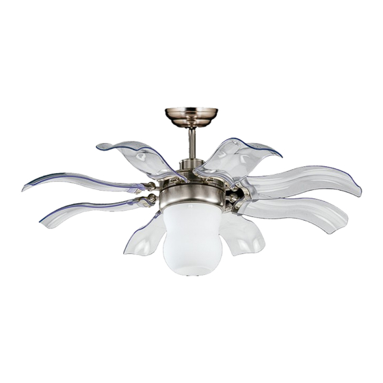
- Página 1 Deckenventilator 10031082...
-
Página 2: Tabla De Contenido
Fehlersuche und Fehlerbehebung 10 Hinweise zur Entsorgung 11 Konformitätserklärung 11 Technische Daten Artikelnummer 10031082 Stromversorgung 220-240 V ~ 50-60 Hz Sicherheitshinweise • Lassen Sie die Installation von einem ausgebildeten Elektriker durchführen. • Stellen Sie vor der Installation den Strom am Sicherungskasten ab. -
Página 3: Geräteübersicht Und Zubehör
Geräteübersicht und Zubehör Geräteteile Fernbedienung Zubehörteile A Halterung a Fernbedienung h Spannschrauben für die Halterung 2x B Aufhängestange b Fernbedienungs-Abdeckung i Schrauben für die Halterung 2x C Schirm c Receiver j Klammer 1x (optional) D Abdeckung d Fernbedienungs-Wandhalterung k Schrauben für die Flügel 17x E Motor e Batterie l Unterlegscheiben für die Flügel 17x... -
Página 4: Installation
Installation WICHTIG: Bringen Sie den Ventilator nicht an Zwischendecken oder rissigen Decken an. Der Abstand zwischen Ventilator und Boden muss mindestens 2,3 m betragen. Befestigen Sie die Halterung sicher an der Decke. Wählen Sie dazu eine der folgenden beiden Befestigungsmethoden für die Halterung. - Página 5 Schrauben Sie die Flügel an die Halterung und ziehen Sie die Schrauben fest an. Drücken und verbiegen Sie die Flügel während der Installation nicht, damit sie später während des Betriebs nicht flattern. Drehen Sie die Birne in die Fassung und befestigen Sie anschließend den Glasschirm mit 3 Schrauben.
- Página 6 Befestigen Sie den Receiver an der Halterung (siehe „Fernbedienung und Receiver“). Lösen Sie die zwei Schrauben an der Halterung, schieben Sie den Schirm hoch, bis er die Halterung abdeckt und ziehen Sie die Schrauben wieder fest. Versichern Sie sie dass alle Kabel korrekt verbunden sind, bevor Sie die Abedckung hochschieben.
-
Página 7: Fernbedienung Und Receiver
Fernbedienung und Receiver Wichtige Hinweise • Achten Sie darauf, dass die Fernbedienung nicht herunterfällt, sie könnte sonst beschädigt werden. • Kürzen Sie nicht das Antennenkabel des Receivers. • Falls Sie die Fernbedienung längere Zeit nicht benutzen, entnehmen Sie die Batterien, damit sie nicht in der Fernbedienung auslaufen können. -
Página 8: Frequenz-Einstellung
Frequenz-Einstellung 1. Zum Ändern der Einstellung lassen Sich die DIP-Schalter hoch und runter schieben. 2. Receiver und Fernbedienung besitzen beide jeweils vier dieser Schalter, die jeweils gleich eingestellt sein müssen. Es sind insgesamt 16 verschiedene Einstellungen möglich. 3. Die Einstellung beeinflusst die Frequenz des Fernbedienungssignals, über die der Ventilator bedient wird. 4. -
Página 10: Sicherung Austauschen
Sicherung austauschen Drücken Sie beide Seiten des Sicherungskapsel gegeneinander und drehen Sie sie, um die Kapsel zu öffnen. Entfernen Sie die alte Sicherung aus der Kapsel und ersetzen Sie sie durch eine neue 5A-Sicherung. Zum Verschließen der Kapsel, setzen Sie den Verschluss an die Rillen und drehen Sie ihn wieder fest. -
Página 11: Hinweise Zur Entsorgung
Entsorgung und Konformitätserklärung Befindet sich die linke Abbildung (durchgestrichene Mülltonne auf Rädern) auf dem Pro- dukt, gilt die Europäische Richtlinie 2012/19/EU. Diese Produkte dürfen nicht mit dem nor- malen Hausmüll entsorgt werden. Informieren Sie sich über die örtlichen Regelungen zur getrennten Sammlung elektrischer und elektronischer Gerätschaften. -
Página 12: Technical Data
Troubleshooting 20 Hints on Disposal 21 Declaration of Conformity 21 Technical Data Item number 10031082 Power supply 220-240 V ~ 50-60 Hz Safety Instructions • Installation must be carried out by a qualified electrician. • Turn off the electrical mains at the circuit breaker/fuse box. -
Página 13: Product Description And Accessory
Product Description and Accessory Equipment Parts Remote Control Accessories Packet A Mounting Bracket a Transmitter h Expansion Screws x2 (Optional) B Downrod Set b Transmitter Cover i Screws For Mounting Bracket x2 C Canopy c Receiver j Clasp x1 (Optional) D Decorative Cover d Wall bracket For Transmitter k Blade screws x17... -
Página 14: Installation
Installation IMPORTANT: Do not install the fan onto the partition ceiling or chapped wall. The ceiling fan must be mounted at a min. height of 7.5 ft/2.3 m of clearance from the floor. The mounting bracket must be securely fastened to a structural ceiling member. - Página 15 Screw the fan blades to their brackets and make sure all screws are tightened. Please do not press/ bend the blade during installation for preventing from the wobble. Install the bulb (if needed) into the bracket (The bulb specification depends on on-site situation), attach a bottom lamp cover to fan using 3 ball screws.
- Página 16 Insert the receiver into the mounting bracket (see „Remote Control and Receiver“). Loosen the screws from the mounting bracket, uphold the canopy to cover the mounting bracket, then let the mounted hole aim at the screws, then firm the screws. ATTENTION: Make sure all wires are proper connected.
-
Página 17: Remote Control And Receiver
Remote Control and Receiver Important Hints • To avoid damaging the transmitter prevents dropping or banging the transmitter. • Do not attempt to shorten the receiver’ s antenna wire. • If the transmitter is not used for some time, please remove batteries to avoid leakage. •... -
Página 18: Frequency Settings
Frequency Settings 1. These DIP code can be pushed upward and downward to change the setting. 2. Both of these remote control components (receiver and transmitter) have a set of four switches that need to have the same settings. (The total combination becomes 16 frequency codes). 3. -
Página 20: Fuse Replacement
Fuse Replacement Push both side of the fuse capsule towards each other and twist it to open the fuse capsule. Remove the damaged 5A glass fuse from the capsule then repla- ce a new 5A glass fuse. To close the fuse capsule aline the latch and groove then push in and twist to lock the fuse capsule. -
Página 21: Hints On Disposal
Disposal and Declaration of Conformity According to the European waste regulation 2012/19/EU this symbol on the product or on its packaging indicates that this product may not be treated as household waste. Instead it should be taken to the appropriate collection point for the recycling of electrical and electronic equipment. -
Página 22: Datos Técnicos
Detección y resolución de problemas 30 Indicaciones para la retirada del aparato 31 Declaración de conformidad 31 Datos técnicos Número de artículo 10031082 Suministro eléctrico 220-240 V ~ 50-60 Hz Indicaciones de seguridad • Contacte con un electricista cualificado para realizar la instalación. -
Página 23: Descripción Del Aparato Y Accesorios
Descripción del aparato y accesorios Piezas del aparato Mando a distancia Accesorios A Soporte de montaje a mando a distancia h Tornillo de expansión para soporte x2 B Varilla de extensión b Tapa del mando a distancia i Tornillos para soporte x2 C Cubierta C Receptor j Cierre 1x (opcional) -
Página 24: Instalación
Instalación IMPORTANTE: no monte el ventilador en un falso techo o en techos agrietados. La distancia entre el ventilador y el suelo debe ser de como mínimo 2,3 m. Fije el soporte al techo. A continuación, seleccione uno de los siguientes métodos de fijación para el soporte. - Página 25 Atornille las aspas a sus soportes y apriete bien los tornillos. No presione ni doble las aspas durante la instalación para evitar que se tambaleen durante el funcionamiento del ventilador. Enrosque la bombilla en el portalámparas y a continuación fije la protección de cristal con 3 tornillos.
- Página 26 Fije el receptor al soporte (consulte «Mando a distancia y receptor»). Suelte dos tornillos del soporte, levante la cubierta hasta que cubra el soporte y apriete los tornillos. Asegúrese de que todos los cables estén colocados correctamente antes de subir la cubierta. Interruptor reversible: coloque el interruptor en la posición izquierda para orientar la corriente de aire hacia...
-
Página 27: Mando A Distancia Y Receptor
Mando a distancia y receptor Indicaciones importantes • Tenga en cuenta que el mando a distancia no se caiga, podría dañarse. • No acorte el cable de la antena del receptor. • Si no utiliza el mando a distancia durante un periodo de tiempo prolongado, retire la batería para evitar que se provoque una fuga en el mando a distancia. -
Página 28: Configuración De Frecuencia
Configuración de frecuencia 1. Para modificar los ajustes, levante y baje los interruptores DIP. 2. El receptor y el mando a distancia cuentan con cuatro de estos interruptores que deben ajustarse del mismo modo. En total hay 16 ajustes disponibles. 3. -
Página 30: Sustituir Fusibles
Sustituir fusibles Presione ambos extremos de la cápsula del fusible la una contra la otra y gírelas para abrir la cápsula. Retire el fusible usado de la cápsula y sustitúyalo por otro fusible nuevo de 5A. Para cerrar la cápsula, alinee el cierre y la ranura y vuelva a girarlos. Detección y resolución de problemas Problema Posible causa y solución... -
Página 31: Indicaciones Para La Retirada Del Aparato
Retirada declaración de conformidad Si el aparato lleva adherida la ilustración de la izquierda (el contenedor de basura tachado) entonces rige la normativa europea, directiva 2012/19/UE. Este producto no debe arrojar- se a un contenedor de basura común. Infórmese sobre las leyes territoriales que regulan la recogida separada de aparatos eléctricos y electrónicos. -
Página 32: Fiche Technique
Identification et résolution des problèmes 40 Information sur le recyclage 41 Déclaration de conformité 41 Fiche technique Numéro d’ a rticle 10031082 Alimentation électrique 220-240 V ~ 50-60 Hz Consignes de sécurité • Laisser un électricien qualifié effectuer l’installation. • Avant l’installation, couper le courant électrique au niveau de la boîte à fusibles. -
Página 33: Aperçu De L' A Ppareil Et Accessoires
Aperçu de l’ a ppareil et accessoires Parties de l’appareil Télécommande Accessoires A Support a Télécommande h Vis à poussoir pour le support 2x B Barre d’ a ccroche b Coque de télécommande i Vis pour le support 2x C Cache c Récepteur j Attache 1x (optionnel) D Support... -
Página 34: Installation
Installation IMPORTANT : ne pas monter le ventilateur sur un faux-plafond ou un plafond fissuré. La distance entre le ventilateur et le sol doit être d’ a u moins 2,3 m. Bien fixer le support au plafond. Pour cela, choisir une des deux méthodes de fixation du support suivantes. - Página 35 Visser les pales au support et serrer les vis. Ne pas exercer de pression et ne pas tordre les pales pendant l’installation pour éviter qu’ e lles ne tremblent pendant le fonctionnement du ventilateur. Visser l’ a mpoule dans le culot et fixer enfin l’...
- Página 36 Fixer le récepteur au support de fixation (cf. « Télécommande et récepteur »). Dévisser les deux vis du support de fixation, faire glisser le cache vers le haut jusqu’ à ce qu’il recouvre entièrement le support de fixation et serrer les vis. S’ a ssurer que tous les câbles sont bien branchés avant de faire coulisser le cache.
-
Página 37: Télécommande Et Récepteur
Télécommande et récepteur Remarques importantes • Veiller à ne pas laisser tomber la télécommande pour ne pas l’ e ndommager. • Ne pas raccourcir le câble d’ a ntenne du récepteur. • En cas d’inutilisation prolongée de la télécommande, en sortir les piles pour éviter qu’ e lles ne fuient dans la télécommande. -
Página 38: Réglage De La Fréquence
Réglage de la fréquence 1. Pour modifier le réglage, placer l’interrupteur DIP en position haute ou basse, 2. Le récepteur et la télécommande possèdent chacun 4 interrupteurs qui doivent être réglés à l’identique. En tout, 16 différents réglages sont possibles. 3. -
Página 40: Remplacer Le Fusible
Remplacer le fusible Appuyer sur les deux côtés de la capsule de sécurité et les faire tourner pour ouvrir la capsule. Sortir l’ a ncien fusible de la capsule et le remplacer par un nouveau fusible 5A. Pour verrouiller la capsule, faire coïncider le culot avec les rainures et tourner pour fixer. -
Página 41: Information Sur Le Recyclage
Recyclage et déclaration de conformité Vous trouverez sur le produit l’image ci-contre (une poubelle sur roues, barrée d‘une croix), ce qui indique que le produit se trouve soumis à la directive européenne 2012/19/UE. Renseignez-vous sur les dispositions en vigueur dans votre région concernant la collecte séparée des appareils électriques et électroniques. -
Página 42: Dati Tecnici
Ricerca e risoluzione dei problemi 50 Smaltimento 51 Dichiarazione di conformità 51 Dati tecnici Articolo numero 10031082 Alimentazione 220-240 V ~ 50-60 Hz Avvertenze di sicurezza • L´installazione deve essere eseguita da un elettricista qualificato. • Prima dell´installazione staccare la corrente tramite l´interruttore o la scatola dei fusibili. -
Página 43: Descrizione Del Prodotto E Accessori
Descrizione del prodotto e accessori Componenti Telecomando Accessori dispositivo a Telecomando h Viti a estensione 2x A Staffa di montaggio b Coperchio telecomando i Viti per staffa di montaggio 2x B Asta c Ricevitore j Morsetto 1x (non incluso nella consegna) C Calotta d Supporto a parete per telecomando k Viti per le pale 17x... -
Página 44: Installazione
Installazione IMPORTANTE: non assemblare il ventilatore ad un controsoffitto o ad un soffitto screpolato. La distanza tra il ventilatore e il pavimento deve essere almeno di 2,3 m. Fissare saldamente al soffitto la staffa di montaggio. Scegliere uno dei due metodi per il fissaggio. - Página 45 Avvitare le pale al supporto e serrare le viti. Non premere e non piegare le pale durante l´installazione per evitare che in seguito oscillino mentre sono in funzione. Avvitare la lampadina e fissare la calotta in vetro utilizzando 3 viti. Prima di installare il ventilatore, assicurarsi che il cavo di sicurezza sia fissato al supporto a parete installato...
- Página 46 Fissare il ricevitore alla staffa di montaggio (vedere “Telecomando e ricevitore”). Svitare le due viti sulla staffa di montaggio, sollevare la calotta fino a coprire la staffa e serrare di nuovo le viti. Assicurarsi che tutti i cavi siano collegati correttamente prima di sollevare il coperchio.
-
Página 47: Telecomando E Ricevitore
Telecomando e ricevitore Importanti indicazioni • Non fare cadere il telecomando altrimenti potrebbe danneggiarsi. • Non accorciare il cavo dell´antenna del ricevitore. • In caso di inutilizzo del telecomando, rimuovere le pile. Telecomando e ricevitore Installare prima il ricevitore e inserire poi le pile nel telecomando. Se il telecomando o il ventilatore non funzi- onano correttamente o non funzionano del tutto, provare nel seguente modo: •... -
Página 48: Impostazione Frequenza
Impostare la frequenza 1. Per modificare l´impostazione, spostare l´interruttore DIP verso l´alto e verso il basso. 2. Il ricevitore e il telecomando possiedono ciascuno quattro interruttori. Sono possibili 16 impostazioni diverse. 3. L´impostazione influisce sulla frequenza del segnale del telecomando tramite il quale viene azionato il tele- comando. -
Página 50: Sostituire Un Fusibile
Sostituire il fusibile Premere entrambi i lati della capsula del fusibile uno contro l´altro e ruotarli per aprire la capsula. Rimuovere il vecchio fusibile dalla capsula e sostituirlo con un nuovo fusibile 5 A. Per chiudere la capsula, allineare la chiusura alle scanalature e av- vitarla di nuovo. -
Página 51: Smaltimento
Smaltimento e dichiarazione di conformità Se sul prodotto è presente la figura a sinistra (il cassonetto dei rifiuti mobile sbarrato), si applica la direttiva europea 2012/19/UE. Questi prodotti non possono essere smaltiti con i rifiuti normali. Informarsi sulle disposizioni vigenti in merito alla raccolta separata di dis- positivi elettrici ed elettronici.