Tabla de contenido
Publicidad
Idiomas disponibles
Idiomas disponibles
Enlaces rápidos
SCOPO DEL MANUALE
Questo manuale è stato redatto dal costruttore ed è parte integrante del prodotto.
In esso sono contenute tutte le informazioni necessarie per:
• la corretta sensibilizzazione degli installatori alle problematiche della sicurezza;
• la corretta installazione del dispositivo;
• la conoscenza approfondita del suo funzionamento e dei suoi limiti;
• il corretto uso in condizioni di sicurezza;
La costante osservanza delle indicazioni fornite in questo manuale, garantisce la sicurezza dell'uomo, l'economia
di esercizio e una più lunga durata di funzionamento del prodotto.
Al fi ne di evitare manovre errate con il rischio di incidenti, è importante leggere attentamente questo manuale,
rispettando scrupolosamente le informazioni fornite.
Le istruzioni, i disegni, le fotografi e e la documentazione contenuti nel presente manuale sono di proprietà
APRIMATIC S.p.a. e non possono essere riprodotti in alcun modo, né integralmente, né parzialmente.
Il logo "APRIMATIC" è un marchio registrato di APRIMATIC S.p.a.
PURPOSE OF THE MANUAL
This manual was drawn up by the manufacturer and is an integral part of the product.
It contains all the necessary information:
• to draw the attention of the installers to safety related problems
• to install the device properly
• to understand how it works and its limits
• to use the device under safe conditions
Strict observance of the instructions in this manual guarantees safe conditions as well as effi cient operation and
a long life for the product.
To prevent operations that may result in accidents, read this manual and strictly obey the
instructions provided.
Instructions, drawings, photos and literature contained herein are the exclusive property of the
manufacturer and may not be reproduced by any means.
The "Aprimatic" logo is a trademark registered by Aprimatic S.p.A.
BUT DU MANUEL
Ce manuel a été rédigé par le constructeur et fait partie intégrante du produit.
Il contient toutes les informations nécessaires pour :
• sensibiliser les installateurs aux problèmes liés à la sécurité ;
• installer le dispositif de manière correcte ;
• connaître le fonctionnement et les limites du dispositif ;
• utiliser correctement le dispositif dans des conditions de sécurité optimales ;
Le respect des indications fournies dans ce manuel garantit la sécurité personnelle, une économie de fonctionnement
et une longue durée de vie du produit.
Afi n d'éviter des opérations incorrectes et de ne pas risquer des accidents sérieux, lire attentivement ce manuel et
respecter scrupuleusement les informations fournies.
Les instructions, les dessins, les photos et la documentation contenus dans ce manuel sont la propriété d'APRIMATIC
S.p.A. et ne peuvent être reproduits sous aucune forme, ni intégralement, ni partiellement.
Le logo « Aprimatic » est une marque déposée par Aprimatic S.p.A.
ZWECK DES HANDBUCHS
Dieses Handbuch wurde vom Hersteller verfasst und ist ein ergänzender Bestandteil des Produkts.
Es enthält alle nötigen Informationen für:
• die Sensibilisierung der Monteure für Fragen der Sicherheit;
• die vorschriftsmäßige Installation der Vorrichtung;
• die umfassende Kenntnis ihrer Funktionsweise und ihrer Grenzen;
• die vorschriftsmäßige und sichere Benutzung.
Die Beachtung der in diesem Handbuch enthaltenen Anweisungen gewährleistet die Sicherheit der Personen, den
wirtschaftlichen Betrieb und eine lange Lebensdauer des Produkts.
Zur Vermeidung von Fehlbedienung und somit Unfallgefahr dieses Handbuch aufmerksam durchlesen und die
Anweisungen genau befolgen.
Die Anleitungen, Zeichnungen, Fotos und Dokumentationen in diesem Handbuch sind Eigentum von APRIMATIC
S.p.A. und dürfen in keiner Weise ganz oder teilweise reproduziert werden.
Das Logo „Aprimatic" ist ein eingetragenes Warenzeichen der Aprimatic S. p. A.
OBJETO DEL MANUAL
Este manual ha sido redactado por el constructor y forma parte integrante del producto.
El mismo contiene todas las informaciones necesarias para:
• la correcta sensibilización de los instaladores hacia los problemas de la seguridad
• la correcta instalación del dispositivo
• el conocimiento en profundidad de su funcionamiento y de sus límites
• el correcto uso en condiciones de seguridad
La constante observación de las indicaciones suministradas en este manual, garantiza la seguridad del hombre,
la economía del ejercicio y una mayor duración de funcionamiento del producto.
Con el fi n de evitar maniobras equivocadas con riesgo de accidente, es importante leer atentamente este manual,
respetando escrupulosamente las informaciones suministradas.
Las instrucciones, los dibujos, las fotografías y la documentación que contiene este manual son propiedad de
APRIMATIC S.p.a. y no pueden ser reproducidas en ninguna manera, ni integral ni parcialmente.
El logotipo "Aprimatic" es una marca registrada de Aprimatic S. p. A.
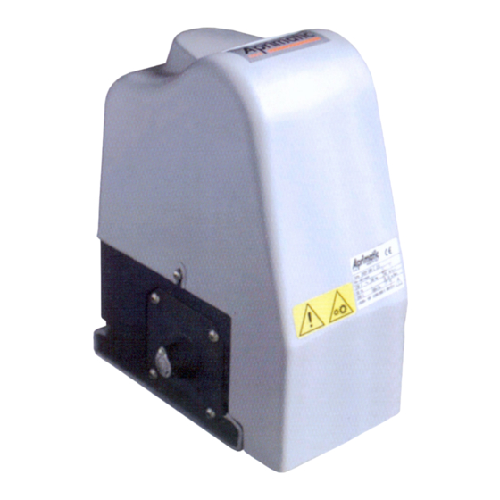
ONDA 500/501
ONDA 800/801
Motoriduttore 230V per cancello scorrevole
230V gearmotor for sliding gate
Motoréducteur 230V pour portail coulissant
Getriebemotor 230V für Schiebetor
Motorreductor 230V para cancela corredera
Istruzioni di installazione meccanica Uso e
Mechanical installation, Use and Mainte-
Notice d'installation mécanique, d'Utilisation
Anleitung für die mechanische Installation,
Instrucciones para la instalación mecánica,
el uso y el mantenimiento
Manutenzione
nance instructions
et d'Entretien
Gebrauch und Wartung
Publicidad
Tabla de contenido

Manuales relacionados para Aprimatic ONDA 500


Resumen de contenidos para Aprimatic ONDA 500
- Página 1 Afi n d’éviter des opérations incorrectes et de ne pas risquer des accidents sérieux, lire attentivement ce manuel et respecter scrupuleusement les informations fournies. Les instructions, les dessins, les photos et la documentation contenus dans ce manuel sont la propriété d’APRIMATIC S.p.A. et ne peuvent être reproduits sous aucune forme, ni intégralement, ni partiellement.
-
Página 2: Tabla De Contenido
Posizionamento e fissaggio motoriduttore ..................... 8 5. Installazione cremagliera Sequenze di montaggio ........................10 Fissaggio piastrini finecorsa ......................... 11 6. Regolazione della frizione (solo per ONDA 500/800) 7. Note per l'utente Sblocco manuale (manovra di emergenza) ..................12 8. Note per il manutentore Ricerca guasti ............................ -
Página 3: Norme Di Sicurezza E Obblighi Dell'installatore
CANCELLI AD ANTE SCORREVOLI ONDA 500/501/800/801 per l’uso e la manutenzione. Queste istruzioni devono NORME DI SICUREZZA E OBBLIGHI essere conservate e consegnate a tutti i futuri possibili DELL’INSTALLATORE utilizzatori. Per lavorare nel pieno rispetto delle norme di sicurezza •... -
Página 4: Descrizione Del Prodotto
10 Kg Uso previsto e Campo d’impiego Grado di protezione IP 44 ONDA 500/501 è progettato per automatizzare il movimento di Temperature di funzionamento cancelli scorrevoli con peso max. di 500 Kg, se adibiti ad uso -25 ÷ +70 °C con apparecchiatura all'interno residenziale domestico e di 300 kg se adibiti ad uso condominiale. -
Página 5: Controlli Preliminari Sul Cancello
CANCELLI AD ANTE SCORREVOLI ONDA 500/501/800/801 Tab.2 COMPONENTI FORNITI CON L ATTUATORE TÀ Fig.3 attuatore con chiave di sblocco piastra di fi ssaggio a slitta piastrini finecorsa (con grani di fissaggio) istruzioni; avvertenze; garanzia Aprimatic DA ACQUISTARE SEPARATAMENTE CATALOGO PF500/800 - piastra di fondazione... -
Página 6: Predisposizione Allacciamenti Elettrici
CANCELLI AD ANTE SCORREVOLI ONDA 500/501/800/801 PREDISPOSIZIONE ALLACCIAMENTI ELETTRICI Fig.6 Il collegamento deve essere eseguito da personale qualifi cato e con l'apparecchiatura Attenzione NON collegata alla rete. L’intero impianto deve essere realizzato da personale Per i collegamenti seguire le istruzioni qualifi... -
Página 7: Installazione Motoriduttore
CANCELLI AD ANTE SCORREVOLI ONDA 500/501/800/801 INSTALLAZIONE MOTORIDUTTORE Fig.8 Il motoriduttore viene fi ssato al suolo mediante la PIASTRA A . Questa può essere saldata SLITTA SU PIASTRA DI FONDAZIONE OPPURE FISSATA DIRETTAMENTE AL SUOLO MEDIANTE TASSELLI A se il suolo è suffi cientemente... -
Página 8: Fissaggio Della Slitta Con Tasselli
CANCELLI AD ANTE SCORREVOLI ONDA 500/501/800/801 Zincospray o vernice antiruggine. Eliminare eventuali Fig.13 sbavature di cemento, o ruggine sulla superficie della piastra di fondazione, specie sulle tacche di riferimento. • Posizionare la piastra a slitta in corrispondenza delle tacche di riferimento, perfettamente allineata longitudinalmente all'anta e alla corretta distanza dal cancello (Fig.13). -
Página 9: Installazione Cremagliera
CANCELLI AD ANTE SCORREVOLI ONDA 500/501/800/801 INSTALLAZIONE CREMAGLIERA Fig.16 Sono disponibili due tipi di cremagliera: A - cremagliera in acciaio zincato (CZ) (mm) B - cremagliera in plastica con anima in acciaio (CP) L'altezza di installazione H (Fig.16 o 17) dipende dal tipo di cremagliera installata e dal tipo di pignone. -
Página 10: Sequenze Di Montaggio
CANCELLI AD ANTE SCORREVOLI ONDA 500/501/800/801 Sequenze di montaggio Fig.18 CREMAGLIERA IN ACCIAIO Fissare i distanziali al centro delle asole di ogni spezzone di cremagliera tramite le relative viti e rondelle (Fig.18). Aprire completamente il cancello. AVVERTENZA - quando si posizionano gli spezzoni sul pignone, il motoriduttore deve essere bloccato ;... -
Página 11: Fissaggio Piastrini Finecorsa
CANCELLI AD ANTE SCORREVOLI ONDA 500/501/800/801 Fissaggio piastrini fi necorsa Fig.23 L’attuatore è dotato di un fi necorsa elettromeccanico con asta a molla. L'azionamento è determinato da due piastrini metallici da fi ssare sulla cremagliera in modo da impegnare il 50 mm fi... -
Página 12: Note Per L'utente
CANCELLI AD ANTE SCORREVOLI ONDA 500/501/800/801 NOTE PER L'UTENTE Fig.26 IMPORTANTE Si consiglia di far effettuare periodicamente un controllo per constatare il buon funzionamento dell’attuatore, da parte di personale specializzato, con frequenza non superiore ai 12 mesi. Sblocco manuale (manovra di emergenza) In caso di mancanza di corrente, sbloccare l’attuatore per... - Página 13 Positioning and fixing the gearmotor ....................19 5. Fitting the bar rack Mounting sequences ..........................21 FixIng the limit switch plates ........................ 22 6. Clutch adjustment (only ONDA 500/800) 7. Notes for users Manual release (emergency manouvre) ....................23 8. Notes for maintenance technicians Troubleshooting............................
-
Página 14: Safety Standards And Installer Obligations
SLIDING GATES ONDA 500/501/800/801 • Keep away from moving mechanical parts. Keep away SAFETY STANDARDS AND INSTALLER from the operating range of the device during operation. OBLIGATIONS Do not try to obstruct the movement of the device as such Installers must proceed as follows to conform with safety action may be hazardous. -
Página 15: Product Technical Features
10 Kg Destined use and Working range Degree of protection IP 44 ONDA 500/501 operator is designed to automate the movement of max. 500 Kg sliding gates for residential-use, Operating temperature or of max. 300 kg for condominium-use. -25 ÷ +70 °C... -
Página 16: Gate Preliminary Checks
SLIDING GATES ONDA 500/501/800/801 .2 - COMPONENTS SUPPLIED WITH THE OPERATOR Fig.3 Operator with release key Sliding securing plate Limit switch plates (with fi xing screws) instructions; warnings; warranty Aprimatic TO BE PURCHASED SEPARATELY CATALOGUE PF500/800 - Foundation plate CZ - Galvanized steel rack... -
Página 17: Preparing Electrical Connections
SLIDING GATES ONDA 500/501/800/801 PREPARING ELECTRICAL CONNECTIONS Fig.6 The electric connections must be made by qualifi ed personnel and with the control Warning unit disconnected from the mains. Carry out the connections following the control unit The system must only be installed by skilled personnel instructions. -
Página 18: Fitting The Gearmotor
SLIDING GATES ONDA 500/501/800/801 FITTING THE GEARMOTOR Fig.8 Gearmotor is secured into the ground with the appropriate . The sliding plate can be welded to a SLIDING SECURING PLATE , or (if the base is strong enough) FOUNDATION PLATE SECURED... -
Página 19: Fixing The Sliding Plate With Screw Anchors
SLIDING GATES ONDA 500/501/800/801 surface of the foundation plate, specially on the reference Fig.13 marks. • Position the sliding securing plate in connection with the reference marks, perfectly parallel to the sliding gate and at a correct distance from the gate (Fig.13). -
Página 20: Fitting The Bar Rack
SLIDING GATES ONDA 500/501/800/801 FITTING THE BAR RACK Fig.16 Two types of rack are available: A - Galvanized steel rack (CZ) (mm) B - Plastic rack with steel core (CP) The rack height must be respected H (Fig.16 or 17 - depending on the type of rack and pignon installed). -
Página 21: Mounting Sequences
SLIDING GATES ONDA 500/501/800/801 Mounting sequences Fig.18 GALVANIZED STEEL RACK Fix the spacers to the rack with screws and washers, making sure that the screws pass through the centre of the slot (Fig.18). Throw the gate completely open. WARNING - during the positionings of the rack pieces on the pinion, the gearmotor must be locked ;... -
Página 22: Fixing The Limit Switch Plates
Fig.24 CLUTCH ADJUSTMENT ( only ONDA 500/800) The adjustable mechanical clutch make possible to limit the thrust force of the gate againts any obstacle in its path. ADJUSTMENT •... -
Página 23: Notes For Users
SLIDING GATES ONDA 500/501/800/801 NOTES FOR USERS Fig.26 IMPORTANT At regular intervals, we recommend carrying out regular checks by specialised personnel to ensure that the operator is running smoothly. Do this at least once every 12 months. Manual release (emergency manouvre) - Página 24 5. Fixation de la crémaillère Séquence des opérations de montage ....................32 FIxation des plaques de fin de course ....................33 6. Réglage de l’embrayage (seulement pour ONDA 500/800) 7. Informations pour l’usager Déverrouillage manuel (manœuvres d’urgence) .................. 34 8. Informations pour le responsable d’entretien Dépannage ............................
-
Página 25: Normes De Sécurité Et Obligations De L'installateur
PORTAILS COULISSANTS ONDA 500/501/800/801 attentivement parce qu’elles contiennent des informations NORMES DE SÉCURITÉ ET OBLIGATIONS importantes pourl’utilisation et l’entretien. Ces instructions DE L’INSTALLATEUR doivent être conservées et remises à tous les utilisateurs Pour travailler dans le respect des normes de sécurité, il faut: futurs éventuels. -
Página 26: Caractéristiques Du Produit
Degré de protection IP 44 Utilisation prévue et Secteur d’emploi Températures de fonctionnement ONDA 500/501 a été conçu pour automatiser le mouvement des portails coulissants de MAXI 500 Kg à usage résidentiel avec platine à bord -25 ÷ +70 °C -25 ÷... -
Página 27: Contrôles Préliminaires Sur Le Portail
PORTAILS COULISSANTS ONDA 500/501/800/801 .2 - COMPOSANTS FOURNIS AVEC LE MOTORÉDUCTEUR RÉF TÉ Fig.3 Actionneur avec clé de déverrouillage Plaque de fi xation à glissière Plaquettes fi n de course (avec vis de fi xation) instructions; avertissements; garantie Aprimatic À ACHETER SEPARAMMENT... -
Página 28: Préparation Des Raccordements Électriques
PORTAILS COULISSANTS ONDA 500/501/800/801 PRÉPARATION DES RACCORDEMENTS ÉLECTRIQUES Fig.6 Le raccordement doit être effectué par du personnel qualifi é. Vérifi er que la platine ne Attention soit pas branchée au secteur. Toute l’installation doit être réalisée par des personnes Les branchements s’effectuent de la façon indiquée qualifi... -
Página 29: Fixation Du Motoréducteur
PORTAILS COULISSANTS ONDA 500/501/800/801 FIXATION DU MOTORÉDUCTEUR Fig.8 Le motoréducteur est fi xé au sol au moyen de la PLAQUE . La plaque à glissière, peut être soudée à une À GLISSIÈRE PLAQUE DE FONDATION OU BIEN FIXÉE AU SOL PAR DES VIS TAMPONNÉES (si le sol est plat et de bonne consistance). -
Página 30: Fixation De La Plaque À Glissière Par Vis Tamponnées
PORTAILS COULISSANTS ONDA 500/501/800/801 spray et de la peinture anti-rouille. Nettoyer la plaque de Fig.13 fondation en éliminant les bavures éventuelles de béton ou de rouille, surtout sur les encoches de repérage. • Placer la plaque à glissière en la faisant correspondre aux encoches et l’aligner à... -
Página 31: Fixation De La Crémaillère
PORTAILS COULISSANTS ONDA 500/501/800/801 FIXATION DE LA CRÉMAILLÈRE Fig.16 Il existe deux types de crémaillère éligibles: A - crémaillère en acier zingué (CZ) (mm) B - crémaillère en plastique avec âme en acier (CP) La hauteur H de fi xation de la crémaillère (Fig.16 ou 17) doit être déterminée par rapport au type de crémaillère et de... -
Página 32: Séquence Des Opérations De Montage
PORTAILS COULISSANTS ONDA 500/501/800/801 Séquence des opérations de montage Fig.18 CRÉMAILLÈRE EN ACIER Fixer les entretoises au centre des trou oblong de la crémaillère avec les vis et rondelles prévues (Fig.18). Ouvrir complètement le portail AVERTISSEMENT - pendant les positionnement des tronçons sur le pignon, le motoréducteur doit être bloqué... -
Página 33: Fixation Des Plaques De Fin De Course
à nouveau et faire glisser doucement le portail dans un sens jusqu’à ce qu’il y ait un click d’enclenchement. RÉGLAGE DE L’EMBRAYAGE ( seulement pour ONDA 500/800) L’embrayage mécanique réglable permit de limiter la poussée que l’actionneur exerce sur un obstacle qui en empêche le mouvement du portail. -
Página 34: Informations Pour L'usager
PORTAILS COULISSANTS ONDA 500/501/800/801 INFORMATIONS POUR L’USAGER Fig.26 IMPORTANT - Il est conseillé de faire effectuer périodiquement un contrôle pour vérifier le bon fonctionnement de l’actionneur, par du personnel spécialisé avec une fréquence qui ne dépasse pas 12 mois. Déverrouillage manuel (manœuvres d’urgence) En cas de manque de courant, déverrouiller l’actionneur... - Página 35 SCHIEBETOREN ONDA 500/501/800/801 INHALTSVERZEICHNIS Sicherheitsvorschriften und Pfl ichten des Installateurs Hinweise für den Benutzer Im Text verwendete Begriffe und Symbole 1. Beschreibung des Antriebs Vorgesehene Verwendung und Einsatzbereich ................... 37 Restrisiken ............................37 Technische Daten ..........................37 Abmessungen ............................37 Transportverpackung ...........................
-
Página 36: Im Text Verwendete Begriffe Und Symbole
SCHIEBETOREN ONDA 500/501/800/801 SICHERHEITSVORSCHRIFTEN UND HINWEISE FÜR DEN BENUTZER PFLICHTEN DES INSTALLATEURS • Die folgenden Angaben und Hinweise sind Bestandteil des Produkts. Sie müssen dem Benutzer ausgehändigt F ü r d a s A r b e i t e n u n t e r v o l l e r B e a c h t u n g d e r... -
Página 37: Beschreibung Des Antriebs
800 kg bei Einsatz im Privathäusern und bis 500 kg bei Abb.1 Einsatz in Wohnanlagen beschränkt. Jeder andere Einsatz ist nicht von Aprimatic S.p.A. genehmigt. Vorsicht Der Einsatz des Produktes für andere als die vorgesehenen oder für unsachgemäße Zwecke ist untersagt. Das Produkt darf keinesfalls verändert oder umgestaltet werden. -
Página 38: Betriebsvorbereitende Arbeitsvorgänge
SCHIEBETOREN ONDA 500/501/800/801 Tab.2 BAUTEILE GELIEFERTE MIT DER ANTRIEB Abb.3 Antrieb (mit Entriegelungschlüssel) Befestigungsplatte mit Schlitten Endschalter Platte (mit Befestigungsdübel) Anleitung; Hinweise; Garantie Aprimatic DAS GETRENNT ZU KAUFEN IST VERKAUFSKATALOG PF500/800 - Fundamentplatte CZ - Plastik-Zahnstange OBLIGATORISCH CP - Stahl-Zahnstange / 5x1m Z20 - Ritzel 20 Zähne... -
Página 39: Vorbereitung Der Elektrischen Anschlüsse
SCHIEBETOREN ONDA 500/501/800/801 VORBEREITUNG DER ELEKTRISCHEN Fig.6 Verbindung nur durch qualifiziertes ANSCHLÜSSE Personal. Vor Durchführen der Verbindung sollte man sich vergewissern, daß die Steuerung nicht an Netzstrom angeschlossen ist. Achtung Zum Elektroanschlüsse siehe die mitgelieferte des Die gesamte Anlage muss von Fachkräften gemäß den im Steuereinheit. -
Página 40: Befestigung
SCHIEBETOREN ONDA 500/501/800/801 BEFESTIGUNG GETRIEBEMOTOR Fig.8 Der Getriebemotor wird mit der SCHLITTENPLATTE Boden befestigt. Diese kann an der FUNDAMENTPLATTE FESTGESCHWEISST ODER MITHILFE VON SPREIZDÜBELN ODER bei ausreichend kompaktem und CHEMISCHEN DÜBELN ebenem Boden) direkt am Boden befestigt werden. HAUBEN BEFESTIGUNGS... -
Página 41: Montage Des Getriebemotors
SCHIEBETOREN ONDA 500/501/800/801 oder den Rost an der Plattenoberfl äche - besonders aber Abb.13 an den Referenz-Kerben - beseitigen. • Die Gleitplatte an den Markierungen positionieren, dabei auf ihre perfekte Längsfl uchtung zum Torfl ügel und den korrekten Abstand vom Tor achten (Abb.13). -
Página 42: Befestigung Regelstange
SCHIEBETOREN ONDA 500/501/800/801 BEFESTIGUNG ZAHNSTANGE Fig.16 Zwei Arten von Schrank stehen zur Verfügung: A - Zahnstange aus verzinktem Stahl (CZ) (mm) B - Plastik-Zahnstange ist mit einem Stahlkern bestück (CP) Die Höhe Installation der Zahnstange H (Abb.16 oder 17) hängt vom eingesetzen Ritzel-und zahnstengentyp ab. - Página 43 Das Ritzel muss in Achse mit dem ersten Distanzstück sein SCHIEBETOREN ONDA 500/501/800/801 Reihenfolge der Montage Fig.18 ZAHNSTANGE AUS VERZINKTEM STAHL Die Distanzstücke mit den entsprechenden Schrauben und Unterlegscheiben in der Mitte der Langlöcher der Zahnstange befestigen (Abb.18). Das Tor ganz öffnen.
-
Página 44: Befestigung Der Anschlagplatten
SCHIEBETOREN ONDA 500/501/800/801 Befestigung der Anschlagplatten Abb.23 Der Antrieb besitzt einen elektromechanischen Endschalter mit Federstange. Der von zwei Metallplatten betrieben wird, die auf die Zahnstange montiert werden und die 50 mm Endschalterstange bei Annäherung an die Torpositionen “Vollständig geöffnet” und Vollständig geschlossen” auslösen. -
Página 45: Hinweise Für Den Benutzer
SCHIEBETOREN ONDA 500/501/800/801 HINWEISE FÜR DEN BENUTZER Abb.26 WICHTIG - Es wird empfohlen, die einwandfreie Funktionstüchtigkeit des Antriebs regelmäßig (mindestens alle 12 Monate) durch Fachpersonal überprüfen zu lassen. Entriegelung (Notsteuerungen) Bei Stromausfall muss der Antrieb entriegelt werden (Abb.22), um das Tor von Hand öffnen zu können: •... - Página 46 5. Montaje de la cremallera Secuencia de montaje .......................... 54 Fijación de las placas final carrera ....................... 55 6. Ajuste del embrague (solo para ONDA 500/800) 7. Notas para el usuario Desbloqueo manual (maniobra de emergencia) .................. 56 8. Notas para el técnico de mantenimiento Búsqueda de averías ...........................
-
Página 47: Normas De Seguridad Y Obligaciones Del Instalador
CANCELA COREDERA ONDA 500/501/800/801 • Esta automatización debe utilizarse exclusivamente para NORMAS DE SEGURIDAD Y OBLIGACIONES el uso al cual ha sido destinada. Todo uso que no sea el DEL INSTALADOR indicado es impropio y por tanto peligroso. Para trabajar respetando las normas de seguridad es necesario: •... -
Página 48: Descripción Del Producto
10 Kg Uso previsto y Campo de aplicación Grado de protección IP 44 ONDA 500/501 ha sido diseñado para automatizar el Temperaturas de funcionamiento movimiento de todas aquellas cancelas correderas con peso -25 ÷ +70 °C con el equipo incorporado Máx. -
Página 49: Comprobación Preliminares Cancela
CANCELA COREDERA ONDA 500/501/800/801 C O M P O N E N T E S S U M I N I S T R A D O S C O N E L Tab.2 Fig.3 MOTORREDUCTOR motorreductor con llave de desbloqueo placa de sujeción de corredera... -
Página 50: Predisposición De La Instalación Eléctrica
CANCELA COREDERA ONDA 500/501/800/801 PREDISPOSICIÓN DE LA INSTALACIÓN Fig.6 ELÉCTRICA La conexión debe ser realizada por personal cualificado y con el cuadro de maniobras NO conectado a la red. Atención Para la conexión eléctrica atenerse a las Toda la instalación debe ser llevada instrucciones del equipo de control. -
Página 51: Installación Motorreductor
CANCELA COREDERA ONDA 500/501/800/801 INSTALLACIÓN MOTORREDUCTOR Fig.8 El motorreductor se fija al suelo mediante la PLACA . Esta puede ser soldada a una CORREDERA PLACA DE FUNDICIÓN O TAMBIÉN FIJADA AL SUELO POR MEDIO DE TORNILLOS DE SEGURIDAD si la consistencia de la base DE EXPANSIÓN O QUÍMICOS... -
Página 52: Sujecion De La Placa Corredera Con Tornillos
CANCELA COREDERA ONDA 500/501/800/801 u óxido de la superfi cie de la placa, especialmente de las Fig.13 ranuras de referencia. • Colocar la placa corredera en correspondencia con las ranuras, perfectamente alineada longitudinalmente con la puerta y a la distancia adecuada de la cancela (Fig.13). -
Página 53: Montaje De La Cremallera
CANCELA COREDERA ONDA 500/501/800/801 MONTAJE DE LA CREMALLERA Fig.16 Se pueden utilizar dos tipos de cremallera: A - cremallera de acero galvanizado (CZ) (mm) B - cremallera de plástico con núcleo de acero (CP) La altura de la cremallera H (Fig.16 o 17) depiende da el tipo de cremallera y da el tipo de piñón instalados. -
Página 54: Secuencia De Montaje
CANCELA COREDERA ONDA 500/501/800/801 Secuencia de montaje Fig.18 CREMALLERA DE ACERO Fijar los distanciadores en el centro de los ojales de cada trozo de cremallera con sus tornillos y arandelas (Fig.18). Abrir completamente la cancela. ADVERTENCIA - cuando se colocan los trozos sobre el piñón, el motorreductor debe ser bloqueado ;... -
Página 55: Fijación De Las Placas Final Carrera
CANCELA COREDERA ONDA 500/501/800/801 Fijación de las placas fi nal carrera Fig.23 El actuador está provisto de un fi nal de carrera electromecánico con varilla de muelle. Su accionamiento está determinado por dos placas metálicas que se montan sobre la cremallera 50 mm y que accionan la varilla del fi... -
Página 56: Notas Para El Usuario
CANCELA COREDERA ONDA 500/501/800/801 NOTAS PARA EL USUARIO Fig.26 ¡IMPORTANTE! Se aconseja realizar periódicamente un control para comprobar el buen funcionamiento del actuador, por personal especializado, con una periodicidad no superior a los 12 meses. Desbloqueo manual (maniobra de emergencia) -
Página 57: Dichiarazione Ce Di Conformità
ONDA 500/501/800/801 - 57 -... - Página 58 ONDA 500/501/800/801 - 58 -...
- Página 59 ONDA 500/501/800/801 - 59 -...
- Página 60 Aprimatic S.p.A. via Leonardo da Vinci, 414 40059 Villa Fontana di Medicina - Bologna - Italia Tel. +39 051 6960711 - fax +39 051 6960722 info@aprimatic.com - www.aprimatic.com...