Publicidad
Idiomas disponibles
Idiomas disponibles
Enlaces rápidos
H-10033
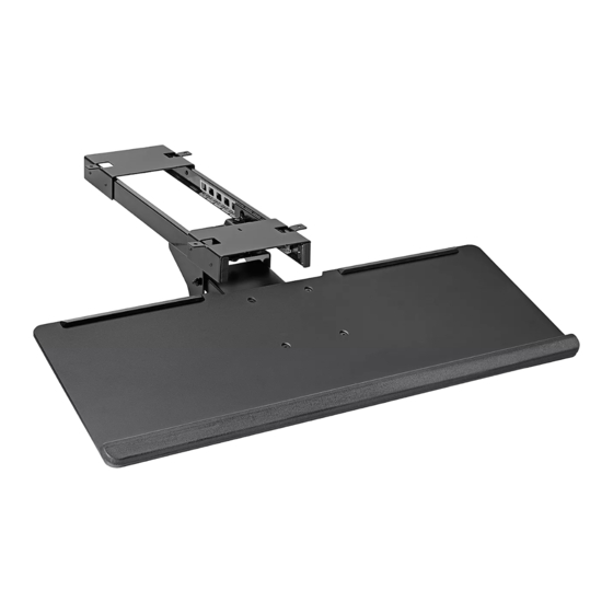
UNDER-DESK
KEYBOARD TRAY
TOOLS NEEDED
Drill Bit
Drill
(optional)
Track x 1
M5 x 8 mm Bolt x 8
NOTE: Keyboard tray weight capacity is 4.4 lbs.
NOTE: Keyboard tray can be assembled with
or without brackets, allowing for universal
attachment to a variety of desks.
• If no obstructions are underneath the desktop,
brackets do not need to be installed. Keyboard
tray can be attached flush to the underside of the
desktop.
• If obstructions are underneath the desktop, such
as a desk's support frame, brackets will need to be
installed to make the keyboard tray compatible.
For example, if attaching to Uline's Adjustable Height
Desks, brackets must be installed to the track to
clear the support frame underneath desktop.
PAGE 1 OF 9
1-800-295-5510
uline.com
Two Person Assembly
Phillips
Recommended
Screwdriver
Mount x 1
Wood Screw x 4
ASSEMBLY
PARTS
Keyboard Tray x 1
M5 x 12 mm Bolt x 4
WITHOUT BRACKETS
1. Attach the mount to the track using four
M5 x 8 mm bolts. Tighten using Phillips screwdriver.
(See Figure 1)
Figure 1
Track
Mount
Para Español, vea páginas 4-6.
Pour le français, consulter les pages 7-9.
Bracket x 2
(optional)
Cap x 4
M5 x 8 mm Bolt
0522 IH-10033
Publicidad

Resumen de contenidos para Uline H-10033
- Página 1 • If obstructions are underneath the desktop, such as a desk's support frame, brackets will need to be installed to make the keyboard tray compatible. For example, if attaching to Uline's Adjustable Height Track Desks, brackets must be installed to the track to clear the support frame underneath desktop.
- Página 2 ASSEMBLY CONTINUED 2. Attach keyboard tray to mount using four M5 x 12 mm WITH BRACKETS bolts. Tighten using Phillips screwdriver. Insert four With both brackets angled outward, attach brackets caps to cover bolts. (See Figure 2) to track with four M5 x 8 mm bolts. Tighten using Phillips screwdriver.
- Página 3 NOTE: If desired, pilot holes can be created using a drill and a 4 mm drill bit. The pilot holes should go no deeper than 9/16". Figure 7 Desktop Flush Wood Screw 1-800-295-5510 uline.com PAGE 3 OF 9 0522 IH-10033...
- Página 4 Riel compatible. Por ejemplo, si la fija a los Escritorios de Altura Ajustable de Uline, debe instalar los soportes al riel para despejar el armazón de soporte debajo del escritorio. Base...
- Página 5 CONTINUACIÓN DEL ENSAMBLE CON SOPORTES Fije la repisa para teclado a la base usando cuatro pernos M5 x 12 mm. Apriete utilizando un desarmador 1. Con ambos soportes en ángulo hacia afuera, fije de cruz. Inserte cuatro tapas para cubrir los pernos. (Vea los soportes al riel con cuatro pernos M5 x 8 mm.
- Página 6 NOTA: Si lo desea, puede crear orificios guía con un taladro y una broca de 4 mm. Los orificios guía no deben ser más profundos que 9/16". Diagrama 7 Escritorio A Ras Tornillo para Madera 800-295-5510 uline.mx PAGE 6 OF 9 0522 IH-10033...
- Página 7 être installés pour rendre le plateau à clavier compatible. Par exemple, si le plateau est fixé à un bureau à hauteur réglable Uline, des supports doivent être installés sur le rail afin d'éviter le cadre de support sous la surface. Dispositif de...
- Página 8 MONTAGE SUITE AVEC SUPPORTS 2. Fixez le plateau à clavier au dispositif de montage avec quatre boulons M5 x 12 mm. Serrez le tout en En gardant les deux supports orientés vers l'extérieur, vous servant du tournevis cruciforme. Insérez quatre fixez-les au rail à...
- Página 9 Bouton REMARQUE : Vous pouvez percer des avant- Plateau à clavier trous avec une perceuse munie d'une mèche de 4 mm au besoin. Les avant-trous ne doivent pas dépasser 9/16 po de profondeur. 1-800-295-5510 uline.ca PAGE 9 OF 9 0522 IH-10033...


