Publicidad
Idiomas disponibles
Idiomas disponibles
Enlaces rápidos
WWW.BROAN-NUTONE.COM
Serial number:
WWW.BROAN-NUTONE.CA
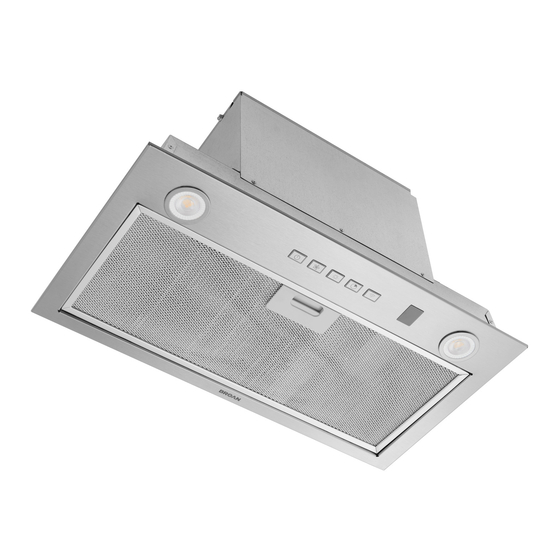
Powerpack Inserts
Model numbers: PM400SSV (RIC #20400170),
USE & CARE INSTRUCTIONS
PM400SSV
(RIC #20400170)
PM600SSV (RIC #20600170)
INSTALLATION,
PM600SSV
(RIC #20600170)
1105025B
Publicidad

Manuales relacionados para Broan-NuTone Powerpack Inserts PM400SSV


Resumen de contenidos para Broan-NuTone Powerpack Inserts PM400SSV
- Página 1 WWW.BROAN-NUTONE.COM WWW.BROAN-NUTONE.CA Powerpack Inserts Model numbers: PM400SSV (RIC #20400170), PM600SSV (RIC #20600170) INSTALLATION, USE & CARE INSTRUCTIONS PM400SSV (RIC #20400170) PM600SSV (RIC #20600170) Serial number: 1105025B...
- Página 2 Safety ........... . . 3-4 Installation .
- Página 3 To register your product, please visit our website: In the United States - broan-nutone.com In Canada - broan-nutone.ca For Technical Support, call: In the United States - 800-637-1453 In Canada - 800-567-3855 Installer: Leave this manual with the homeowner. READ AND SAVE THESE INSTRUCTIONS...
- Página 4 WARNING TO REDUCE THE RISK OF A RANGE TOP GREASE FIRE: A. Never leave surface units unattended at high settings. Boilovers cause smoking and greasy spillovers that may ignite. Heat oils slowly on low or medium settings. B. Always turn hood ON when cooking at high heat or when flambeing food (i.e. Crepes Suzette, Cherries Jubilee, Peppercorn Beef Flambé).
- Página 5 For ADA compliance installation guidelines, please type the model number into our website. RECOMMENDED TOOLS AND ACCESSORIES • Measuring tape • Scissors (to cut metal foil duct tape) • Phillips screwdriver no. 2 • Pencil • Nut driver or socket 3/8” •...
- Página 6 This will allow easier cleaning and provide protection to the cabinetry. Refer to table at right to find the liner model corresponding to the cabinet style and width. Visit www.broan-nutone.com or www.broan-nutone.ca to view METAL LINER FIG. 2 specific model information.
- Página 7 PREPARE THE CABINET WARNING CUT A HOLE IN THE BOTTOM OF THE CABINET The cabinet must be secured to wall studs or other wooden framework behind the drywall to support the weight of this unit. Failure to do so may cause personal injury or damage to countertop or cooktop.
- Página 8 PREPARE THE CABINET Narrow edge 6. Install the cabinet brackets as follow (FIG. 10): configuration Align the bracket flush with the bottom of the right cabinet side panel, with the hooks marked position (E) between the bottom embossed holes. For the narrow edge configuration, trace a line on the top of the bracket.
- Página 9 PREPARE THE CABINET ( ’ CONT 7. Measure the distance between both bottom bracket edges (F) (FIG. 11). The table below shows the approriate distance needed. ARROW EDGE IDE EDGE From 19-3/8” to From 19-9/16” to < 19-9/16” 19-13/16” FIG. 11 If the measured distance needs to be shortened, screw two Screws in bottom no.
- Página 10 PREPARE THE UNIT LL INSTALLATIONS NOTE: Since this manual covers 2 different unit models, some details in the following illustrations may slightly differ from your unit. 1. If present, remove all protective polyfilm from the unit and/ or parts. 2. Remove the grease filter by pushing down on latch tab and FIG.
- Página 11 PREPARE THE UNIT ( ’ SCREWS CONT ’ ORIZONTAL EXHAUST INSTALLATION ONLY CONT 7. Remove the 6 screws (2 per side and 2 in front) retaining the blower support plate to the top of the unit (FIG. 19). SCREWS Carefully lift out and set aside the blower with its support SCREWS plate.
- Página 12 INSTALL THE UNIT 1. Run house power cable between service panel and unit location. Stub out a 2-foot length of power cable inside the cabinet. Insert the power cable in the unit through the 7/8” diameter strain relief previously installed. NOTE: Not necessary if the optional HCK44 cord connection kit is used.
- Página 13 INSTALL THE UNIT ( ’ CONT 3. Lift the unit until contact is made between the unit flange and cabinet. Secure the unit to the cabinet using 4 no. 8 x 5/8” wood screws included in parts bag (2 screws per side). Use upper or lower holes (1, 2, 3, 4, 5 or 6) (FIG.
- Página 14 INSTALL THE UNIT ( ’ CONT ’ ORIZONTAL EXHAUST INSTALLATION ONLY CONT 6. Reinstall and secure the faceplate to the unit using its 4 retaining screws (two per side, circled in FIG. 28). Plug the blower cable to its connector on faceplate (FIG. 28). FIG.
- Página 15 WIRING WARNING WHITE WIRE Risk of electric shock. Electrical wiring must be done by qualified personnel in accordance with all BLACK GREEN WIRE applicable codes and standards. Before connecting GROUND wires, switch power off at service panel and lock SCREW service disconnecting means to prevent power from being switched on accidentally.
- Página 16 OPERATION PM400SSV (20400170) NOTES: 1. Each time a key is pressed, a beep is emitted to acknowledge the command. To disable, when the fan and lights are OFF, press on the Lights key ( ) for 5 seconds.
- Página 17 OPERATION ( ’ CONT PM600SSV (20600170) NOTES: 1. Each time a key is pressed, a beep is emitted to acknowledge the command. To disable, when the fan and lights are OFF, press on the Lights key ( ) for 5 seconds.
- Página 18 Bluetooth SIG, Inc. and any use of the key for 3 seconds. Once the key backlight is flashing, such marks by Broan-NuTone is under license. Other trademarks and trade names are those of their press the key again for 10 seconds.
- Página 19 OPERATION ( ’ CONT WI-FI/BLUETOOTH (PM400SSV PM600SSV) ® SING YOUR ONNECTED SING OOGLE SSISTANT NABLED PEAKER OR ISPLAY Now that your unit is properly connected, you can Say “Hey Google” and Google will start listening to your experience all the functionalities through the app. commands.
- Página 20 OPERATION ( ’ ALL UNITS HEAT SENTRY™ Your unit is equipped with a HEAT SENTRY™ thermostat. This thermostat is a device that will turn on or speed up the blower if it senses excessive heat above the cooking surface. 1) If blower is OFF - it turns blower ON to HIGH speed. 2) If blower is ON at a lower speed setting - it turns blower up to HIGH speed.
- Página 21 OPERATION ( ’ CODE READY TECHNOLOGY™ ACTIVATION The Code Ready Technology option allows to change the blower output from the factory setting (PM400SSV: 400 CFM, PM600SSV: 600 CFM) to a maximum of 300 CFM for PM400SSV unit and 400 CFM or 300 CFM for PM600SSV unit.
- Página 22 MAINTENANCE STAINLESS STEEL CLEANING ALWAYS SWITCH OFF THE ELECTRICITY SUPPLY • Regularly wash with clean cloth or rag soaked BEFORE CARRYING OUT ANY OPERATIONS ON THE APPLIANCE. with warm water and mild soap or liquid dish detergent. Grease Filter • Always clean in the direction of original polish The grease filter should be cleaned frequently.
- Página 23 PM400SSV (20400170) 23 23...
- Página 24 PM600SSV (20600170) 24 24...
- Página 25 PM400SSV (20400170) EY NO UMBER ESCRIPTION SV08487 OUND ADAPTER DAMPER S99271702 17 μ APACITOR S97021510 ’ 400 CFM LOWER ASS S1108581 S98012198-808 F ACEPLATE S1108579 OFT TOUCH BUTTON CONTROL S99271694 MODULE ASSEMBLY PAIR HARCOAL FILTER WITH CLIPS NOT SHOWN DUCTED INSTALLATION S99010464 .
- Página 26 PM600SS (20600170) EY NO UMBER ESCRIPTION SV08487 OUND ADAPTER DAMPER S99271379 25 μ APACITOR S97021509 ’ 600 CFM LOWER ASS S1108581 S98012198-812 F ACEPLATE S1108580 OFT TOUCH BUTTON CONTROL S99271694 MODULE ASSEMBLY PAIR HARCOAL FILTER WITH CLIPS CLIPS NOT SHOWN DUCTED S99010464 .
- Página 27 Limited Warranty Warranty Period and Exclusions: Broan-NuTone LLC and Venmar Ventilation ULC (either being the “Company”) warrants to the original consumer purchaser of its product (“you”) that the product (the “Product”) will be free from material defects in the Product or its workmanship for a period of one (1) year from the date of original purchase (or such longer period as may be required by applicable law).
- Página 28 WWW.BROAN-NUTONE.COM WWW.BROAN-NUTONE.CA Hottes encastrées Numéros de modèle : PM400SSV (RIC #20400170), PM600SSV (RIC #20600170) DIRECTIVES D’INSTALLATION, D’UTILISATION ET D’ENTRETIEN PM400SSV (RIC #20400170) PM600SSV (RIC #20600170) Numéro de série : 1105025B...
- Página 29 Sécurité ........... . 3-4 Installation .
- Página 30 Pour enregistrer votre produit, veuillez visiter notre site Internet : Aux États-Unis : broan-nutone.com Au Canada : broan-nutone.ca Pour de l’assistance technique, veuillez composer le numéro de téléphone suivant : Aux États-Unis : 800-637-1453 Au Canada : 800-567-3855 Installateur : Laisser ce manuel au propriétaire.
- Página 31 AVERTISSEMENT AFIN DE RÉDUIRE LES RISQUES DE FEU DE CUISINIÈRE : A. Ne jamais laisser les appareils de cuisson sans surveillance lorsqu’ils sont réglés à feu vif. Les débordements engendrent de la fumée et des déversements graisseux pouvant s’enflammer. Chauffez l’huile lentement, à feu doux ou moyen. B.
- Página 32 Pour connaître les lignes directrices de l’ADA (Americans with Disabilities Act) concernant l’installation, veuillez entrer votre numéro de modèle dans notre site Internet. OUTILS ET ACCESSOIRES RECOMMANDÉS • Ruban à mesurer • Ruban adhésif de métal • Tournevis Phillips n° 2 •...
- Página 33 Cette précaution facilitera le nettoyage et protégera l’armoire. Consulter le tableau ci-contre pour trouver le modèle de revêtement correspondant à la largeur et au style de l’armoire. Visitez le www.broan-nutone.com ou le www.broan-nutone.ca pour plus de détails sur ces modèles. REVÊTEMENT D’ARMOIRE EN MÉTAL FIG.
- Página 34 PRÉPARATION DE L’ARMOIRE AVERTISSEMENT DÉCOUPER UN TROU DANS LA BASE DE L’ARMOIRE L’armoire doit être fixée aux montants ou autre structure derrière la cloison pour supporter le poids de cet appareil. Ne pas suivre cette directive peut entraîner des blessures corporelles ou des dommages à...
- Página 35 PRÉPARATION DE L’ARMOIRE ( SUITE 6. Installer les supports d’armoire comme suit (FIG. 10) : Configuration du Placer le support au même niveau que le bas du rebord étroit panneau droit de l’armoire, en centrant la marque de l’emplacement des crochets (E) entre les trous en relief inférieurs.
- Página 36 PRÉPARATION DE L’ARMOIRE ( SUITE 7. Mesurer la distance entre les rebords du bas des deux supports (F) (FIG. 11). Le tableau ci-dessous indique les distances appropriées nécessaires : EBORD ÉTROIT EBORD LARGE De 19-3/8 po à De19-9/16 po à <...
- Página 37 PRÉPARATION DE L’APPAREIL OUTES LES INSTALLATIONS NOTE : Puisque ce guide couvre 2 différents modèles de hotte, certains détails des illustrations suivantes peuvent différer légèrement de votre appareil. 1. Le cas échéant, retirer toute présence de pellicule de plastique protectrice sur la hotte ou ses pièces. 2.
- Página 38 PRÉPARATION DE L’APPAREIL ( SUITE NSTALLATION EN ÉVACUATION HORIZONTALE SEULEMENT SUITE 7. Retirer les 6 vis (2 à l’avant et 2 par côté) retenant la plaque de support du ventilateur au dessus de la hotte (FIG. 19). Soulever soigneusement cette plaque avec le ventilateur et la mettre de côté.
- Página 39 INSTALLATION DE L’APPAREIL 1. Acheminer le câble d’alimentation électrique du panneau de distribution jusqu’à l’emplacement de l’appareil. Prévoir une longueur de 2 pi à l’intérieur de l’armoire. Passer le câble d’alimentation dans la hotte à travers le serre-fils de 7/8 po de diamètre péalablement installé. NOTE : Non nécessaire si l’ensemble de cordon d’alimentation HCK44 est utilisé.
- Página 40 INSTALLATION DE L’APPAREIL ( SUITE 3. Lever la hotte jusqu’à ce que son rebord s’appuie sur la base de l’armoire. Fixer la hotte à l’armoire à l’aide de 4 vis à bois n˚ 8 x 5/8 po incluses dans le sac de pièces (2 vis par côté).
- Página 41 INSTALLATION DE L’APPAREIL ( SUITE NSTALLATION EN ÉVACUATION HORIZONTALE SEULEMENT SUITE 6. Réinstaller et fixer le châssis sur la hotte à l’aide des 4 vis de retenue (deux par côté, encerclées dans la FIG. 28). Brancher le câble du ventilateur à son connecteur situé sur le châssis.
- Página 42 BRANCHEMENT ÉLECTRIQUE AVERTISSEMENT FIL BLANC Risque d’électrocution. Le raccordement électrique doit être effectué par du personnel qualifié VIS VERTE NOIR conformément aux codes et aux standards en DE MISE À vigueur. Avant d’effectuer le branchement, coupez LA TERRE l’alimentation électrique au panneau de distribution et verrouillez-le pour éviter une mise en marche accidentelle.
- Página 43 FONCTIONNEMENT PM400SSV (20400170) NOTES : 1. À chaque fois qu’on appuie sur une touche, un bip est émis pour confirmer la commande. Pour désactiver, lorsque le ventilateur et l’éclairage sont éteints, appuyer durant 5 secondes sur la touche Éclairage ( ).
- Página 44 FONCTIONNEMENT ( SUITE PM600SSV (20600170) NOTES : 1. À chaque fois qu’on appuie sur une touche, un bip est émis pour confirmer la commande. Pour désactiver, lorsque le ventilateur et l’éclairage sont éteints, appuyer durant 5 secondes sur la touche Éclairage ( ).
- Página 45 SIG, Inc. ® ÉINITIALISATION LUETOOTH et sont utilisés sous licence par Broan-NuTone LLC. Les autres marques de commerce et appellations Pour réinitialiser la connectivité Wi-Fi/ Bluetooth (effacer les commerciales sont celles de leurs propriétaires respectifs. dispositifs sauvegardés et déconnecter du réseau Wi-Fi), appuyer sur la touche durant 3 secondes.
- Página 46 FONCTIONNEMENT ( SUITE WI-FI/BLUETOOTH (PM400SSV PM600SSV) ® ’ TILISATION DE VOTRE APPAREIL CONNECTÉ TILISATION DE L ASSISTANT PERSONNEL HAUT PARLEUR OU ÉCRAN OOGLE Une fois votre hotte connectée convenablement, vous pouvez profiter de toutes ses fonctionalités par l’application. Dites « Hey Google » et Google commencera à écouter Même si vous n’êtes pas dans l’entourage de la hotte, commandes.
- Página 47 FONCTIONNEMENT ( SUITE TOUS LES APPAREILS HEAT SENTRY Votre appareil est équipé d’un thermostat HEAT SENTRY Ce thermostat est un dispositif qui activera ou augmentera la vitesse du ventilateur s’il détecte une chaleur excessive au-dessus de la surface de cuisson. 1) Si le ventilateur est en ARRÊT, il activera le ventilateur en HAUTE vitesse.
- Página 48 FONCTIONNEMENT ( SUITE ACTIVATION DE L’OPTION CODE READY TECHNOLOGY L’option Code Ready Technology permet d’abaisser le débit du ventilateur réglé en usine (PM400SSV : 400 pi³/min, PM600SSV : 600 pi³/min) à un maximum de 300 pi³/min pour la hotte PM400SSV et de 400 pi³/min ou 300 pi³/min pour la hotte PM600SSV.
- Página 49 ENTRETIEN NETTOYAGE DE L’ACIER INOXYDABLE TOUJOURS COUPER L’ALIMENTATION ÉLECTRIQUE AVANT D’EFFECTUER UNE QUELCONQUE OPÉRATION À faire : SUR CET APPAREIL. • Laver régulièrement les surfaces à l’aide d’un chiffon propre imbibé d’eau chaude et de savon Filtre à graisses doux ou de détergent liquide à vaisselle. Le filtre à...
- Página 50 PM400SSV (20400170)
- Página 51 PM600SSV (20600170)
- Página 52 PM400SSV (20400170) N° EPÈRE DE PIÈCE ESCRIPTION TÉ SV08487 DAPTATEUR VOLET PO ROND S99271702 17 μ ONDENSATEUR S97021510 ³/ ENTILATEUR S1108581 ARTE ÉLECTRONIQUE PRINCIPALE S98012198-808 C HÂSSIS S1108579 OMMANDE À EFFLEUREMENT BOUTONS S99271694 DEL ( NSEMBLES DE MODULE PAIRE ILTRE AU CHARBON AVEC CLIPS NON ILLUSTRÉES INSTALLATION SANS CONDUIT SEULEMENT S99010464...
- Página 53 PM600SSV (20600170) N° EPÈRE DE PIÈCE ESCRIPTION TÉ SV08487 DAPTATEUR VOLET PO ROND S99271379 25 μ ONDENSATEUR S97021509 ³/ ENTILATEUR S1108581 ARTE ÉLECTRONIQUE PRINCIPALE S98012198-812 C HÂSSIS S1108580 OMMANDE À EFFLEUREMENT BOUTONS S99271694 DEL ( NSEMBLES DE MODULE PAIRE ILTRE AU CHARBON AVEC CLIPS NON ILLUSTRÉES INSTALLATION SANS CONDUIT SEULEMENT S99010464...
- Página 54 Société sur les sites www.broan-nutone.com et www.broan-nutone.ca. Broan-NuTone LLC 926 West State Street, Hartford, WI 53027 www.broan-nutone.com 800 637-1453 Venmar Ventilation ULC, 550 boul. Lemire, Drummondville, Québec, Canada J2C 7W9 www.broan-nutone.ca 1 800 567-3855...
- Página 55 WWW.BROAN-NUTONE.COM WWW.BROAN-NUTONE.CA Campanas empotrables Números de modelo: PM400SSV(RIC #20400170), PM600SSV (RIC #20600170) INSTRUCCIONES DE INSTALACIÓN, USO Y CUIDADO PM400SSV (RIC #20400170) PM600SSV (RIC #20600170) Número serial: 1105025B...
- Página 56 Seguridad ..........3-4 Instalación .
- Página 57 En EE.UU., registre su campana de cocina en línea en www.broan-nutone.com En Canadá, registre su campana de cocina en línea en www.broan-nutone.ca Para asistencia técnica, marcar el número de teléfono siguiente : En EE.UU. : 800-637-1453 En Canadá : 800-567-3855 INSTALADOR: ENTREGUE ESTE MANUAL AL PROPIETARIO.
- Página 58 ADVERTENCIA PARA REDUCIR EL RIESGO DE QUE ARDA LA GRASA EN LA PARTE SUPERIOR DE LA COCINA: No deje nunca recipientes de cocina a fuego vivo sin vigilancia. Los desbordamientos producen humo y derrames grasientos que pueden inflamarse. Caliente el aceite despacio, a fuego lento o mediano. Ponga en marcha siempre la campana extractora al cocinar a temperaturas elevadas o al cocinar alimentos flameados (crepas Suzette, cerezas jubilee, res con pimienta flambeada).
- Página 59 Para conocer las directrices de la ADA (Ley para estadounidenses con discapacidades) sobre la instalación, indicar su número de modelo en nuestro sitio web. HERRAMIENTAS Y ACCESORIOS RECOMENDADOS • Cinta métrica • Cinta adhesiva metálica • Destornillador Phillips n° 2 •...
- Página 60 Esta medida de precaución facilitará la limpieza y protegerá el gabinete. Consulte la tabla a la derecha para encontrar el modelo de recubrimiento correspondiente con la anchura y el estilo del gabinete. Visite el www.broan-nutone.com o el www.broan-nutone.ca para mayor información sobre estos modelos.
- Página 61 PREPARACIÓN DEL GABINETE ADVERTENCIA CORTAR UN ORIFICIO EN LA BASE DEL GABINETE El gabinete debe fijarse a los montantes murales o a otra estructura de madera situada detrás de la pared. Asegúrese de que pueda soportar el peso de la campana empotrable. De no ser así, podrían producirse lesiones personales o daños en la parte superior de la encimera o de la cocina.
- Página 62 PREPARACIÓN DEL GABINETE ( CONT 6. Instale los soportes de gabinete como sigue (FIG. 10): Configuración Coloque el soporte a ras con la parte inferior del panel borde estrecho derecho del gabinete, centrando la marca de la ubicación de los ganchos (E) entre los orificios inferiores en relieve.
- Página 63 PREPARACIÓN DEL GABINETE ( CONT 7. Medir la distancia entre ambos bordes inferiores de los soportes (F) (FIG. 11). La tabla siguiente indica la distancia adecuada: ORDE ESTRECHO ORDE AMPLIO De 19-3/8 pulg. a De19-9/16 pulg. a < 19-9/16 pulg. 19-13/16 pulg.
- Página 64 PREPARACIÓN DEL APARATO ODAS LAS INSTALACIONES NOTA : Ya que este manual comprende dos modelos distintos de campana, ciertos detalles de las ilustraciones siguientes pueden ser ligeramente diferentes de su aparato. 1. De haberla, retire de la campana y de todas las piezas la película protectora.
- Página 65 PREPARACIÓN DEL APARATO ( TORNILLOS CONT NSTALACIÓN CON SALIDA HORIZONTAL SOLAMENTE CONT 7. Quite los 6 tornillos (2 en la parte delantera y 2 por lado) manteniendo la placa de soporte del ventilador a la parte TORNILLOS TORNILLOS superior del aparato (FIG. 19). Levante cuidadosamente el ventilador y la placa de soporte y póngalos a un lado.
- Página 66 INSTALACIÓN DEL APARATO 1. Encaminar el cable de alimentación del panel de distribución hasta la ubicación del aparato. Prever una longitud de 2 pies en el gabinete. Pasar el cable de alimentación en la campana a través de la abrazadera de cables de un diámetro de 7/8 pulg.
- Página 67 INSTALACIÓN DEL APARATO ( CONT 3. Levantar la campana hasta que su borde quede en la base del gabinete. Sujetar la campana al gabinete usando 4 tornillos para madera n˚ 8 x 5/8 pulg. incluidos en la bolsa de piezas (2 tornillos a cada lado). Usar los orificios superiores o inferiores (1, 2, 3, 4, 5 o 6) (FIG.
- Página 68 INSTALACIÓN DEL APARATO ( CONT NSTALACIÓN CON SALIDA HORIZONTAL SOLAMENTE CONT 6. Vuelva a instalar y fije el panel frontal a la campana usando los 4 tornillos de sujeción (dos por lado, rodeados en la FIG. 28). Enchufe el cable del ventilador a su conector en el panel frontal.
- Página 69 CONEXIÓN ELÉCTRICA ADVERTENCIA HILO BLANCO Peligro de choque eléctrico. La instalación eléctrica debe ser hecha por personal calificado HILO TORNILLO NEGRO de acuerdo con todos los códigos aplicables y VERDE DE normas. Antes de efectuar el empalme, cortar la TOMA DE TIERRA alimentación eléctrica del interruptor y cerrar con securidad para prevenir una alimentación...
- Página 70 FUNCIONAMIENTO PM400SSV (20400170) NOTAS: 1. Cada vez que se pulsa una tecla, se emite un sonido de bip para confirmar la selección. Para desactivar, cuando el ventilador y las luces están apagados, pulsar la tecla Luces ( ) durante 5 segundos.
- Página 71 FUNCIONAMIENTO ( CONT PM600SSV (20600170) NOTAS: 1. Cada vez que se pulsa una tecla, se emite un sonido de bip para confirmar la selección. Para desactivar, cuando el ventilador y las luces están apagados, pulsar la tecla Luces ( ) durante 5 segundos.
- Página 72 La marca y los logotipos de Bluetooth® son marcas se vuelve a ENCENDER la luz de fondo. registradas propiedad de Bluetooth SIG, Inc. y cualquier uso de dichas marcas por parte de Broan-NuTone se hace EINICIO DE LUETOOTH mediante licencia.
- Página 73 FUNCIONAMIENTO ( CONT WI-FI/BLUETOOTH (PM400SSV PM600SSV) ® SO DEL APARATO CONECTADO TILIZACIÓN DEL ASISTENTE PERSONAL ALTAVOZ O PANTALLA DE OOGLE Ahora que su unidad está correctamente conectada, puede probar todas las funcionalidades a través de Diga “Hey Google” y Google comenzará a escuchar la aplicación.Incluso si no está...
- Página 74 FUNCIONAMIENTO ( CONT TODOS LOS APARATOS HEAT SENTRY™ Esta campana está equipada con un termostato Heat Sentry™. Este dispositivo pone en marcha el ventilador cuando detecta un calor excesivo por encima de la superficie sobre la que se cocina. 1) Si el ventilador está apagado, se pondrá en marcha en velocidad ALTA.
- Página 75 FUNCIONAMIENTO ( CONT ACTIVACIÓN DE LA OPCIÓN CODE READY TECHNOLOGY™ La opción Code Ready Technology (CRT) permite modificar el caudal de aire ajustado de fábrica (PM400SSV: 400 pi³/min, PM600SSV: 600 pi³/min) a un máximo de 300 pi³/min para la campana PM400SSV y 400 pi³/min o 300 pi³/min para la campana PM600SSV.
- Página 76 MANTENIMIENTO LIMPIEZA DEL ACERO INOXIDABLE SIEMPRE DESCONECTE LA FUENTE DE ALIMENTACIÓN ANTES DE REALIZAR CUALQUIER INTERVENCIÓN A hacer : SOBRE ESTE APARATO. • Lávelo regularmente con un trapo limpio empapado con una disolución de agua tibia y Filtro de grasa jabón suave o detergente para lavar vajillas.
- Página 77 PM400SSV (20400170)
- Página 78 PM600SSV (20600170)
- Página 79 PM400SSV (20400170) N.° DE PIEZA ESCRIPCIÓN SV08487 DAPTADOR COMPUERTA PULG REDONDO S99271702 17 μ ONDENSADOR S97021510 ³/ ENTILADOR S1108581 LACA PRINCIPAL DE CIRCUITOS S98012198-808 P ANEL FRONTAL S1108579 á ONTROL T CTIL CON TECLAS S99271694 LED ( ONJUNTO DE MÓDULO ILTRO DE CARBÓN CON CLIPS NO ILUSTRADOS PARA INSTALACIÓN SIN CONDUCTO...
- Página 80 PM600SSV (20600170) N.° DE PIEZA ESCRIPCIÓN SV08487 DAPTADOR COMPUERTA PULG REDONDO S99271379 25 μ ONDENSADOR S97021509 ³/ ENTILADOR S1108581 LACA PRINCIPAL DE CIRCUITOS S98012198-812 P ANEL FRONTAL S1108580 á ONTROL T CTIL CON TECLAS S99271694 LED ( ONJUNTO DE MÓDULO ILTRO DE CARBÓN CON CLIPS NO ILUSTRADOS INSTALACIÓN SIN CONDUCTO SOLAMENTE...
- Página 81 Garantía limitada Periodo y exclusiones de la garantía: Broan-NuTone LLC o Venmar Ventilation ULC (sea esta la “Compañía”) garantiza al consumidor comprador original de su producto (“usted”) que el producto (el “Producto”) estará libre de defectos en materiales o en mano de obra, por un periodo de un (1) año a partir de la fecha de compra original (o por un periodo mayor según sea requerido por la legislación aplicable).