Publicidad
Idiomas disponibles
Idiomas disponibles
Enlaces rápidos
KM-400S
ACCIONADOR PARA PUERTAS CORREDERAS CON PARO SUAVE
ACTIONNEUR POUR PORTES COULISSANTES À ARRÊT PROGRESSIF
OPERATORS FOR SLIDING GATES WITH GENTLE STOP
ACCIONADOR PARA PORTAS COM CORREDIÇA COM PARAGEM SUAVE
ANTRIEB FÜR SCHIEBETÜREN MIT WEICHER BREMSUNG
MANUAL DE INSTRUCCIONES
NOTICE D´UTILISATION
INSTRUCTIONS MANUAL
MANUAL DE INSTRUÇÕES
BEDIENUNGSANLEITUNG
Publicidad

Manuales relacionados para Erreka KM-400S


Resumen de contenidos para Erreka KM-400S
- Página 1 KM-400S ACCIONADOR PARA PUERTAS CORREDERAS CON PARO SUAVE ACTIONNEUR POUR PORTES COULISSANTES À ARRÊT PROGRESSIF OPERATORS FOR SLIDING GATES WITH GENTLE STOP ACCIONADOR PARA PORTAS COM CORREDIÇA COM PARAGEM SUAVE ANTRIEB FÜR SCHIEBETÜREN MIT WEICHER BREMSUNG MANUAL DE INSTRUCCIONES NOTICE D´UTILISATION INSTRUCTIONS MANUAL MANUAL DE INSTRUÇÕES...
- Página 3 CARACTERISTICAS TÉCNICAS - Peso Máximo en puerta: 400 kg - Alimentación: 230 V-50 Hz. - Bloqueo - Potencia Absorbida: 340 w - Condensador: 8 µF - Intensidad: 1.6 A - Cos U 0,83 - Velocidad de salida: 50 r.p.m - Factor de Protección: IP44 Encoder + Regulador - Seguridad:...
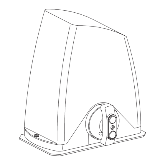
- Página 4 FUNCIONAMIENTO MANUAL - Desbloqueo Manual: - Girar la tapa superior 180º para liberar el bombillo. - Introducir la llave y abrir el bombillo de pistón. - Girar la maneta en sentido horario 270º. - Bloqueo de la puerta: - Girar la cerradura en sentido antihorario 270º. - Introducir el bombillo de la cerradura y girar la tapa superior.
- Página 5 1. Fijación del motor: - Fijar la placa al suelo teniendo en cuenta las dimensiones generales del motor. - Atar el motor a la placa. 2. Colocación de la cremallera: - Colocar la cremallera sobre la puerta teniendo en cuenta las dimensiones del motor colocado en el suelo. - Caso de que sea necesario compensar la altura del motor con los tornillos de regulación de altura.
- Página 6 DESCRIPCCIÓN DEL CUADRO A.- Conexionado (1-18) C.- Pulsador Marchas. D.- Válvula reed Abrir/Cerrar. 1. Llave Apertura Total. 2. Común. E.- Fusible 0,3 A. 3. Llave Apertura Peatonal. F.- Conector tarjeta de semáforos. 4. Fotocélula. G.- Selector de 10 dips. 5. F.C. Abrir. 6.
- Página 7 PUESTA EN MARCHA - Antes de alimentar el cuadro a la red, conectar los distintos periféricos al cuadro. Importante: No olvidar conectar el cable de tierra. 1.- Conectar el cuadro a la red (Interruptor general ON-OFF). 2.- Comprobar que el movimiento de apertura de la puerta coincide con el del motor y su correspondiente final de carrera. - Activar el DIP 9 del selector (G) en función de la posición del motor en la puerta.
- Página 8 DIP 5-ON Automático opcional. DIP 8-ON Paro suave activado. DIP 5-OFF NO Automático opcional. DIP 8-OFF Paro suave desactivado. DIP 6-ON Salida intermitente para lámpara. DIP9-ON/OFF Cambia el posicionamiento de los finales DIP 6-OFF Salida para lámpara destellante fija. de carrera (abrir por cerrar y viceversa). DIP 7-ON Encoder habilitado.
- Página 9 - No automático opcional (DIP 5 OFF) Si recibe un “Start” durante el tiempo de espera, se recarga el tiempo de espera. 7.- Programación de la radio (sólo para código trinario 433 Mhz Erreka RSD-001) La programación de la radio se realizará con la puerta cerrada.
- Página 10 CATÁLOGO DE RECAMBIOS...
- Página 11 CATALOGO DE PIEZAS DE RECAMBIO CUADRO ELECTRONICO Nº Referencia Descripción 27A055 Tornillo 5x50 27A021 Tornillo 5x12 27A049 Imán encoder 27A002 Tapa estator 27A037 Estator 02A064 Arandela de muelle 27A002 Tapa estator 27B001 Eje rotor 27A031 Varilla roscada 8x25 12A049 Remache roscado 27A001 Base 27A016...
- Página 12 CERTIFICADO DE GARANTIA Automatismos Erreka garantiza el presente equipo durante un periodo de 2 años a partir de la fecha de suministro. Dicha garantía es aplicable a todo defecto de fabricación. Es responsabilidad del instalador el hacer llegar el equipo a los servicios técnicos autorizados.
- Página 13 CARACTÉRISTIQUES TECHNIQUES - Poids maxi. sur porte: 400 kg. 230 V-50 Hz. - Alimentation: - Verrouillage 340 w - Puissance Absorbée: - Condensateur: 8 µF - Intensité: 1.6 A 0,83 - Cos U - Vitesse de sortie: 50 tr/min IP44 - Facteur de Protection: - Sécurité: Codeur + Régulateur...
- Página 14 FONCTIONNEMENT MANUEL - Déverrouillage Manuel : - Tourner le couvercle supérieur de 180º pour libérer le cylindre. - Introduire la clé et ouvrir le cylindre à piston. - Tourner la manette en sens horaire de 270º. - Verrouillage de la porte: - Tourner la serrure en sens antihoraire de 270º...
- Página 15 1. Fixation du moteur : - Ancrer la plaque au sol en tenant compte des dimensions hors-tout du moteur. - Monter le moteur sur la plaque. 2. Pose de la crémaillère : - Monter la crémaillère sur la porte en tenant compte des dimensions du moteur monté au sol. - Si nécessaire, compenser la hauteur du moteur avec les vis de mise à...
- Página 16 DESCRIPITION DU TABLEAU A.- Câblage (1-18) C.- Bouton-poussoir Marche. 1. Clé Ouverture Totale. D.- Vanne Reed Ouvrir/Fermer. 2. Commun. E.- Fusible 0,3 A. 3. Clé Ouverture Piétonnière. F.- Connecteur carte de feu tricolore. 4. Photocellule. G.- Sélecteur à 10 dips. 5.
- Página 17 MISE EN MARCHE - Avant de mettre le tableau sous tension, brancher les différents périphériques sur le tableau. Important : Ne pas oublier de connecter le câble de terre. 1.- Connecter le tableau au secteur (Interrupteur général ON-OFF). 2.- Vérifier que le mouvement d’ouverture de la porte coïncide avec celui du moteur et de la fin de course correspondante. - Activer le DIP 9 du sélecteur (G) en fonction de la position du moteur sur la porte.
- Página 18 DIP 5-ON Automatique optionnel. DIP 8-ON Arrêt progressif activé. DIP 5-OFF NON Automatique optionnel. DIP 8-OFF Arrêt progressif désactivé. DIP 6-ON Sortie intermittente pour lampe. DIP9-ON/OFF Change le positionnement des fins DIP 6-OFF Sortie pour lampe clignotante fixe. de course (ouvrir au lieu de fermer et vice-versa). DIP 7-ON Codeur habilité.
- Página 19 -Non Automatique optionnel (DIP 5 OFF) Si un “Start” est reçu pendant le temps d´attente, ce temps d´attente est rechargé. 7.- Programmation de la radio (pour code trinaire 433 Mhz Erreka RSD-001 uniquement ) La programmation de la radio est réalisée avec la porte fermée.
- Página 20 CATALOGUE DE PIÈCES DE RECHANGE CARTE ELECTRONIQUE...
- Página 21 CATALOGUE DE PIÈCES DE RECHANGE CARTE ELECTRONIQUE Nº Référence Description 27A055 Vis 5x50 27A021 Vis 5x12 27A049 Aimant codeur 27A002 Couvercle stator 27A037 Stator 02A064 Rondelle à ressort 27A002 Couvercle stator 27B001 Axe rotor 27A031 Tige filetée 8x25 12A049 Rivet fileté 27A001 Base 27A016...
- Página 22 Vérifier que les temps d’ouverture et de fermeture sont adaptés à la longueur de la porte. Si après avoir réalisé toutes les vérifications et réglages indiqués le problème persiste, adressez-vous à votre distributeur ou au service technique ERREKA le plus proche en décrivant avec le plus de précision possible le dysfonctionnement constaté. INSTALLATION DE L’AUTOMATISME Le modèle KM-400S est conforme à...
- Página 23 TECHNICAL SPECIFICATIONS - Maximun weight on gate: 400 kg - Power supply: 230 V-50 Hz. - Locking - Energy consumed: 275 w 8 µF - Condenser: - Current: 1.56 A - Cos U 0,83 - Output speed: 50 r.p.m - Protection level: IP44 - Safety: Encoder + Regulator...
- Página 24 MANUAL OPERATION - Manual unlocking: - Turn the top cover 180º to free the cylinder lock. - Insert the key and open the piston lock. - Turn the lever clockwise 270º. - Locking the gate: - Turn the lock anticlockwise 270º. - Insert the cylinder lock and turn the top cover.
- Página 25 1.Fastening the motor in position: - Fix the plate to the ground, taking into account the general dimensions of the motor. - Fasten the motor to the plate. 2.Fastening the rack in position: - Fasten the rack to the gate, taking into account the dimensions of the motor on the ground. - If necessary, compensate the height of the motor with height-adjustment screws.
- Página 26 DESCRIPITION OF THE CIRCUIT BOARD A. Connections (1-18) C. Start pushbutton 1. Full opening switch D. Open/Close reed valve 2. Common E. 0.3 A fuse 3. Pedestrian opening switch F. Traffic light card connector 4. Photocell G. 10-dip selector 5. Open end stop H.
- Página 27 START-UP - Before connecting the circuit board to the mains, connect the various peripherals to the circuit board. Important: Remember to connect the earth cable. 1. Connect the circuit board to the mains (general ON-OFF switch). 2. Align the turn directions of the motor with the end stops. - Activate the DIP 9 of the selector (G) in accord with the position of the motor on the gate.
- Página 28 DIP 5-ON Optional automatic. DIP 8-ON Slow down activated. DIP 5-OFF NO Optional automatic. DIP 8-OFF Slow down deactivated. DIP 6-ON Flashing light output. DIP9-ON/OFF Change the position of the ends of sweep DIP 6-OFF Flashing light on (not flashing) output. (open instead of close and vice versa).
- Página 29 -No optional automatic (DIP 5 OFF) if “Start” is received during the wait time, the wait time is reset. 7.- Radio programming (for 433 Mhz Erreka RSD-001 trinary code only) Radio programming must be done with the door closed. The radio recordings for pedestrian and total opening are independent, and they may even correspond to different controls with different codes.
- Página 30 SPARE PARTS CATALOGUE...
- Página 31 SPARE PARTS CATALOGUE ELECTRONIC BOARD Nº Référence Description 27A055 5x50 screw 27A021 5x12 screw 27A049 Encoder magnet 27A002 Stator cover 27A037 Stator 02A064 Spring washer 27A002 Stator cover 27B001 Rotor spindle 27A031 8x25 threaded rod 12A049 Threaded rivet 27A001 Base 27A016 Base plate 66-L 508-009...
- Página 32 Check if the opening and closing times are in accord with the length of the gate. If the fault persists after you have made all the checks and adjustments, go to your nearest distributor or ERREKA technical service with as many details as possible about the fault.
- Página 33 CARACTERÍSTICAS TÉCNICAS - Peso Máximo na porta: 400 kg. - Alimentação: 230 V-50 Hz. - Bloqueio - Potência Absorvida: 340 w - Condensador: 8 µF 1.6 A - Intensidad: - Cos U 0,83 50 r.p.m - Velocidade de saída: IP44 - Factor de Protecção: - Segurança: Encoder + Regulador...
- Página 34 FUNCIONAMENTO MANUAL - Desbloqueio Manual: - Rodar a tampa superior 180º para libertar a bomba. - Introduzir a chave e abrir a bomba do pistão. - Rodar a maneta no sentido dos ponteiros do relógio 270º. - Bloqueio da porta: - Rodar a fechadura no sentido contrário ao dos ponteiros do relógio 270º.
- Página 35 1. Fixação do motor: - Fixar a placa ao chão tendo em conta as dimensões gerais do motor. - Fixar o motor à placa. 2.Colocação da cremalheira: - Colocar a cremalheira sobre a porta tendo em conta as dimensões do motor colocado no chão. - No caso de ser necessário compensar a altura do motor com os parafusos de regulação de altura.
- Página 36 DESCRIÇÃO DO QUADRO A.- Cablagem (1-18) C.- Botão de funcionamento. 1. Chave Abertura Total. D.- Válvula Reed Abrir/Fechar. 2. Comum. E.- Fusível 0,3 A. 3. Chave Abertura para peões. F.- Conector placa de semáforo. 4. Fotocélula. G.- Selector de 10 dips. 5.
- Página 37 ACCIONAMENTO - Antes de alimentar o quadro à rede, ligue os diversos periféricos ao quadro. Importante: Não se esqueça de ligar o cabo de terra. 1.- Ligue o quadro à rede (Interruptor geral ON-OFF). 2.- Verificar que o movimento de abertura da porta coincide com o do motor e o seu correspondente final de curso. - Activar o DIP 9 do selector (G) em função da posição do motor na porta.
- Página 38 DIP 5-ON Automático opcional. DIP 8-ON Paragem suave activada. DIP 5-OFF NÃO Automático opcional. DIP 8-OFF Paragem suave desactivada. DIP 6-ON Saída intermitente para lâmpada. DIP9-ON/OFF Muda o posicionamento dos finais DIP 6-OFF Saída para lâmpada intermitente fixa. de curso (abrir por fechar e vice-versa). DIP 7-ON Encoder habilitado.
- Página 39 - Não automático opcional (DIP 5 OFF) Se receber um “Start” durante o tempo de espera, o tempo de espera é recarregado. 7.- Programação do rádio (só para código trinário 433 Mhz Erreka RSD-001) A programação da rádio será realizada com a porta fechada.
- Página 40 CATÁLOGO DE PEÇAS DE SUBSTITUIÇÃO...
- Página 41 CATÁLOGO DE PEÇAS DE SUBSTITUIÇÃO Descrição N.º Referencia 27A055 Parafuso 5x50 27A021 Parafuso 5x12 27A049 Íman encoder 27A002 Tampa do estator 27A037 Estator 02A064 Anilha de mola 27A002 Tampa do estator 27B001 Eixo do rotor 27A031 Vareta roscada 8x25 12A049 Rebite roscado 27A001 Base...
- Página 42 CERTIFICADO DE GARANTIA A empresa Automatismos Erreka garante o presente equipamento durante um período de 24 meses a partir da data de fornecimento. A dita garantia é aplicável a todos os defeitos de fabricação.
- Página 43 TECHNISCHE DATEN - Stromversorgung: 230 V-50 Hz. - Höchstgewicht der Tür: 400 kg. 275 W - Aufgenommene Leistung: - Blockierung: 1.56 A - Stromstärke: - Kondensator: 8 mF - Ausgangsgeschwindigkeit: 50 U/min - Kos U 0,83 - Sicherheit: Enkoder + Regler IP44 - Schutzfaktor: GESAMTMASSE...
- Página 44 HANDBETRIEB - Entblockieren per Hand: - Drehen Sie den oberen Deckel um 180º Grad, um das Ansaugrohr zu lösen. - Führen Sie den Schlüssel ein und lösen Sie das Ansaugrohr des Kolbens. - Drehen Sie den Hebel im Uhrzeigersinn etwa 270º. Blockieren der Tür: - Drehen Sie das Schloss gegen den Uhrzeigersinn um etwa 270º.
- Página 45 1.Befestigen des Motors: - Befestigen Sie die Halteplatte auf dem Boden, beachten Sie dabei die gesamten Maße des Motors. - Befestigen Sie den Motor auf der Platte. 2.Befestigen der Zahnschiene: - Befestigen Sie den Automatismus an der Basis und ziehen Sie die Innensechskantschrauben (Imbus) zur Befestigung gut an. - Benutzen Sie den Automatismus in manueller Form und überprüfen Sie mit der Bewegung der Tür, ob die Zahnschiene und der Automatismus richtig ausgerichtet sind.
- Página 46 A.- Anschlüsse (1-18) C.- Taster Start. 1. Schlüssel vollst. Öffnung. D.- Reed Ventil Öffnen/Schließen. 2. Stromführendes Kabel.. E.- Sicherung 0,3 A. 3. Schlüssel Fußgängeröffnung. F.- Anschluss Ampelkarte. G.- Platte mit 10 DIP Schaltern 4. Fotozelle. 5. F.Z. Öffnen. H.- LEDs (1, 2, 3, 12, 13 und 14). 6.
- Página 47 INBETRIEBNAHME -Vor dem Anschließen der Schaltplatine an die Stromzufuhr, schließen Sie die verschiedenen Peripheriegeräte an den Schaltkreis an. Achtung: Achten Sie darauf, das Erdungskabel anzuschließen. 1.- Verbinden Sie die Schaltplatine mit dem Stromnetz (Generalschalter ON-OFF). 2.- Bringen Sie die Drehrichtung des Motors und die Endlagen in Übereinstimmung. -Aktivieren Sie den DIP 9 der Schaltplatte (G), entsprechend der Position des Motors in der Tür.
- Página 48 DIP 5-ON Automatik optional. DIP 8-ON Weiche Bremsung aktiviert. DIP 5-OFF KEINE optionale Automatik. DIP 8-OFF Weiche Bremsung deaktiviert. DIP 6-ON Ausgang blinkend für Lampe. DIP9-ON/OFF Änderung der Position der DIP 6-OFF Ausgang für Blinklampe mit Dauerstrom Endlagen (Öffnen für Schließen und umgekehrt). DIP 7-ON Enkoder eingeschaltet.
- Página 49 -KEINE optionale Automatik (DIP 5 OFF) Wenn ein “Start” während der Wartezeit eingegeben wird, beginnt die Wartezeit von vorne. 7.- Programmierung des Senders (Nur für trinären code 433 Mhz Erreka RSD-001) Die Programmierung des Senders wird mit dem geschlossenen Tor ausgefürth.
- Página 50 LISTE DER ERSATZTEILE...
- Página 51 ERSATZTEILE Referenz Beschreibung 27A055 Schraube 5x12 27A021 Enkoder Magnet 27A049 Stator Deckel 27A002 Stator 27A037 Unterlegscheibe der Feder 02A064 Stator Deckel 27A002 Rotorachse 27B001 Gewindestab 8x25 27A031 Schraube 5x12 12A049 Niete mit Gewinde 27A001 Grundsockel 27A016 Grundplatte 66-L 508-009 Kondensator 8 mF 26A071 Schraubenmutter 8 27A054...
- Página 52 Landes vornehmen zu lassen, in dem die Anlage eingebaut wird. GARANTIEZERTIFIKAT Automatismos Erreka gewährleistet für dieses Produkt eine Garantie von 12 Monaten vom Zeitpunkt der Auslieferung an. Die Garantie besteht für alle Fehler bei der Herstellung. Es liegt beim Installateur, die Anlage dem autorisierten technischen Kundendienst zukommen zu lassen.