Lifetime 9594 Manual Del Usuario
Ocultar thumbs
Ver también para 9594:
- Instrucciones de ensamble (24 páginas) ,
- Manual de instrucciones (76 páginas) ,
- Instrucciones de ensamblaje (24 páginas)
Publicidad
Enlaces rápidos
UNIVERSAL
MOUNTING KIT
MODEL #9594
ASSEMBLY INSTRUCTIONS AND OWNER'S
MANUAL
SUPPORT D'EXTENSION POUR LE PANNEAU DE BASKET-BALL UNI-
#9594
4
To ensure your safety, do not attempt to assemble the universal system without reading and following all instructions carefully. Identify and inventory
the parts using the parts list on Page 2.
Um Ihre sicherheit zu wahren, sollten sie nicht versuchen, das Universal System zu montieren, ohne alle anleitungen gründlich gelesen und befolgt
zu haben. Identifizieren und überprüfen sie die bestandteile auf ihre vollständigkeit, indem sie die bestandteilliste auf Seite 2 benutzen.
Pour garantir votre sécurité, ne tentez pas d'assembler le système
universel sans lire et suivre toutes les instructions avec attention.
Identifiez et faites l'inventaire des pièces en utilisant la liste des pièces
en Page 2.
Para su seguridad personal, no trate de armar el sistema universal sin
leer y seguir cuidadosamente todas las instrucciones y advertencias.
INSTRUCTION #1032615 B
WWW.LIFETIME.COM
**U.S. and Canada customers ONLY**
IF ASSISTANCE IS NEEDED,
DO NOT CONTACT THE STORE!!!
CALL OUR CUSTOMER SERVICE DEPARTMENT at 1 (800) 225-3865
HOURS: 7:00 a.m. to 5:00 p.m. Monday through Friday (Mountain Standard Time)
**For customers outside the U.S. or Canada, please contact the store for assistance.**
INSTRUCTIONS D'ASSEMBLAGE ET MANUEL DE L'UTILISATEUR
SOPORTE DE EXTENSIÓN
UNIVERSAL PARA LOS TABLEROS DE
BALONCESTO.
INSTRUCCIONES DE ENSAMBLAJE Y MANUAL DEL
VISIT THE LIFETIME WEB SITE:
UNIVERSAL BASKETBALL
ZIELBRETTTRÄGER
MONTAGE-ANTEILUNGEN UND GEBRAUCHSANWEISUNG
VERSEL
MODÈLE No. 9594
Nº DE MODELO 9594
USUARIO
®
MODELL NR. #9594
WARNUNG
1/14/2009
1
Publicidad

Manuales relacionados para Lifetime 9594


Resumen de contenidos para Lifetime 9594
- Página 1 1/14/2009 ® VISIT THE LIFETIME WEB SITE: WWW.LIFETIME.COM **U.S. and Canada customers ONLY** IF ASSISTANCE IS NEEDED, DO NOT CONTACT THE STORE!!! CALL OUR CUSTOMER SERVICE DEPARTMENT at 1 (800) 225-3865 HOURS: 7:00 a.m. to 5:00 p.m. Monday through Friday (Mountain Standard Time) **For customers outside the U.S.
- Página 2 PARTS LIST BESTANDTEILLISTE LISTE DES PIÈCES Part # Description Beschreibung Description 800355 Extension Bracket Verlängerungsstück Support d’extension 800356 Stud Bracket Befestigungselement für die Support de poutre Wandpfosten 800357 Diagonal Support Diagonalstützen Support diagonal 800358 Pole Mount Bracket Befestigungselement für die Stange Support d’installation sur poteau 850056...
-
Página 3: Ensamblaje
® THIS MOUNTING BRACKET IS FOR USE WITH LIFETIME DIESES BEFESTIGUNGSELEMENT DARF NUR MIT LIFETIME ® ZIELBRETTERN BACKBOARDS ONLY. VERWENDET WERDEN. ESTE SOPORTE DE MONTAJE DEBE USARSE SOLAMENTE CON CE SUPPORT D’INSTALLATION EST CONÇU POUR L’UTILISATION AVEC DES PANNEAUX ®... - Página 4 NOTE: There are three ways of mounting the Extension Bracket: OPTION 1, WALL MOUNT pg. 7-11; OPTION 2, ROOF MOUNT pgs. 12-14; OPTION 3, POLE MOUNT pgs. 15-18. Read all of the instructions thoroughly before beginning assembly to decide which option is best suited for your use.
- Página 5 INDEPENDIENTEMENTE DE LA OPCIÓN QUE SE USE, DEBEN COMPLETARSE LOS PASOS 1 AL 3. QUELLE QUE SOIT L’OPTION CHOISIE, IL FAUT IMPÉRATIVEMENT SUIVRE LES ÉTAPES DE 1 À 3. ÉTAPE 1 a. Tenir les supports de panneau (BB) ensemble et insérer l’étrier de 5 1/2” (140 mm)(HN). b.
- Página 6 STEP 3 NOTE: Refer to the instructions included with the Backboard to complete this step. a. Assemble the Rim and attach it to the Backboard according to the instructions included with the Backboard. b. Follow the instructions included with the Backboard to secure the Brackets. SCHRITT 3 ANMERKUNG: Für die Durchführung dieses Schritts nehmen Sie bitte auf die dem Zielbrett beigepackte Anleitung Bezug.
- Página 7 OPTION 1 WALL MOUNT ASSEMBLY MÖGLICHKEIT 1 WANDMONTAGE OPCIÓN 1 MONTAJE A UNA PARED OPTION 1 MONTAGE AU MUR *Most brick walls are not enough to support the wall mount system. if attaching the wall mount system to a brick wall, be sure to secure the wall mount system through the brick and into studs in the wall.* STEP 4 a.
- Página 8 ÉTAPE 4 a. Repérer et marquer deux poutres consécutives dans le mur où vous voulez installer le panneau. b. Si vous voulez que l’anneau soit à la hauteur réglementaire, tracer une ligne horizontale à 115 5/8” (9’ 7 5/8”), c’est-à-dire 293,68 cm du sol. c.
- Página 9 ステップ 4 ステップ 5 内側の穴...
- Página 10 STEP 6 a. Attach the smaller holes in the Diagonal Supports (AC) to the lower holes in the upper Extension Brackets (AA) with a 5/16” x 3/4” Hex Bolt (HC), a 5/16” Flat Washer (HD) and a 5/16” Flange Nut (HB)(6A). STEP 7 a.
- Página 11 STEP 8 TWO PEOPLE ARE NECESSARY FOR THIS STEP a. Carefully lift the Backboard up to the Extension Brackets. b. Secure the large holes in the upper Extension Brackets (AA) to the middle holes in the Backboard Brackets with a 1/2” x 3 1/4” Hex Bolt (HK) and 1/2” Centerlock Nut (HE).
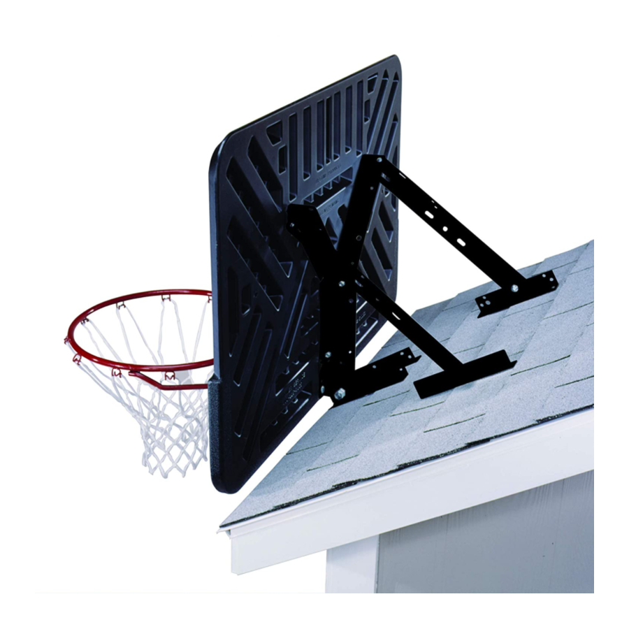
- Página 12 OPTION 2 ROOF MOUNT ASSEMBLY OPTION 2 MONTAGE AU TOIT MÖGLICHKEIT 2 DACHMONTAGE OPCIÓN 2 MONTAJE AL TECHO STEP 4 a. Place two Extension Brackets (AA) 2 1/2” apart on the edge of the roof. The end of the Brackets with the larger hole should be along the edge of the roof (4A).
- Página 13 ÉTAPE 4 a. Mettre deux supports d’extension (AA) à 2 1/2” (63,5 mm) de distance sur le bord du toit. Le bout des supports comportant trois trous devrait correspondre au bord du toit (4A). b. Fixer les supports au toit à l’aide de matériel de fixation adapté au toit (non compris). ÉTAPE 5 a.
- Página 14 STEP 6 a. Attach the long slots in the Stud Brackets (AB) to the upper Brace Angle Piece on each Backboard Bracket with a 5/16” x 3/4” Hex Bolt (HC), a 5/16” Flat Washer (HD) and a 5/16” Flange Nut (HB) (6A). STEP 7 a.
- Página 15 OPTION 3 POLE MOUNT MÖGLICHKEIT 3 MASTMONTAGE OPCIÓN 3 MONTAJE AL POSTE OPTION ASSEMBLAGE AU POTEAU ASSEMBLE THE POLE ACCORDING TO THE MANUFACTURER’S INSTRUCTIONS. STEP 4 a. Make a mark on the pole 115 3/4” (9’ 7 3/4”) from the ground. Place two 3 1/2” U-Bolts (HM) around the pole and slide a Saddle Bracket (AF) over the legs of each U-Bolt.
- Página 16 ÉTAPE 4 a. Faire une marque sur le poteau à 115 3/4” (9’ 7 3/4”) (294 cm) du sol. Mettre deux étriers de 3 1/2” (89 mm) (HM) autour du poteau et enfiler un support cavalier (AF) par-dessus les pattes de chaque étrier. Le rebord inférieur du support cavalier le plus bas devrait atteindre la marque faite sur le poteau à 115 3/4” (294 cm) du sol.
- Página 17 STEP 6 a. Place an Extension Bracket (AA) at the top of a Pole Mount Bracket. b. While holding the Extension Bracket in place, place the end of a Diagonal Support (AC) next to the Extension Bracket so the smaller hole in the Support lines up with the lower hole in the Bracket.
- Página 18 STEP 7 TWO PEOPLE ARE NOW NECESSARY FOR ASSEMBLY. a. Carefully lift the Backboard up to the Pole Mount Assembly. b. Line up the large holes at the ends of the lower Extension Brackets (AA) with the bottom holes in the Backboard Brackets. Line up the hole in the Diagonal Support (AC) with the holes in both Brackets.