Tabla de contenido
Publicidad
Idiomas disponibles
Idiomas disponibles
Enlaces rápidos
P70, P72, and P170 Series Controls for Dual
Pressure Applications
Installation Instructions
Applications
The P70, P72, and P170 Controls for Dual Pressure
Applications provide combined high and low pressure
control of compressors on commercial refrigeration and
air conditioning applications.
IMPORTANT: Except for those models listed as
refrigeration temperature limiting controls, use this
P70, P72, and P170 Series Controls for Dual
Pressure Applications only as an operating control.
Where failure or malfunction of the P70, P72, or
P170 Pressure Control could lead to personal injury
or property damage to the controlled equipment or
other property, additional precautions must be
designed into the control system. Incorporate and
maintain other devices, such as supervisory or
alarm systems or safety or limit controls, intended to
warn of or protect against failure or malfunction of
the P70, P72, or P170 Pressure Control.
P70S and P170S models have independently operated
high and low pressure Single-Pole Double-Throw
(SPDT) switches that can be wired to satisfy a variety
of control requirements. These adaptable controls have
a high pressure manual reset lockout mechanism that
is convertible to automatic reset. See Table 1.
P70L, M, N, and P170L, M, N models have a Single-
Pole Single-Throw (SPST) switch. Models are
available with automatic or manual reset lockout
options. Models with manual reset are available with
either high-side-only manual reset, or low-side and
high-side manual reset. (See Table 1 and Table 3.)
Ammonia compatible models are available (P70L and
P70M only). See Table 2.
Refer to the
P70, P72, and P170 Series Controls for Dual Pressure Applications Installation
QuickLIT Web site
for the most up-to-date version of this document.
P72 models have a Double-Pole Single-Throw (DPST)
switch with load-carrying contacts that can provide
direct control of 208/240 VAC, single-phase motors up
to 3 hp, 480, and 600 VAC single-phase
non-compressor motors and 208/220 VAC, 3-phase
motors up to 5 hp. See Table 3.
These controls are available in several pressure
ranges and are compatible with most common
refrigerants. Ammonia-compatible models are also
available (P70L and P70M only). See Table 2.
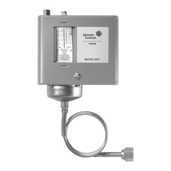
The MICRO-SET® option provides fine adjustment of
the differential setting for precision pressure control of
low pressure applications.
Some models feature Limited Knob Adjustment, which
restricts adjustment of the pressure settings and deters
over-adjustment or tampering. See Low Pressure
Limited Knob Adjustment.
A Manual Reset Lockout option does not allow the
pressure control to reset automatically after CUT OUT
is reached, and provides shutdown capability for
unmonitored equipment. See Manual Reset Operation.
NEMA 1 enclosures are standard on most models.
NEMA 3R enclosures are also available.
Table 1 through Table 2 list the standard models and
features of P70, P72, and P170 controls for dual
pressure applications. These standard models are
available through most authorized
Johnson Controls/PENN® distributors.
Part No. 24-8607-0, Rev. H
Issued March 2016
Instructions
1
Publicidad
Tabla de contenido

Manuales relacionados para Johnson Controls Serie


Resumen de contenidos para Johnson Controls Serie
- Página 1 Models with manual reset are available with Johnson Controls/PENN® distributors. either high-side-only manual reset, or low-side and high-side manual reset. (See Table 1 and Table 3.) Ammonia compatible models are available (P70L and P70M only).
- Página 2 Table 1: Standard Model P70, P72, and P170 MICRO-SET® Dual Pressure Controls for Non-Corrosive Refrigerants Model Code Switch Low Pressure Side High Pressure Side Pressure Limited Number Action psig (kPa) psig (kPa) Connector Knob Adjustment Range Differential Range Differential (Non- Adjustable) SPST 12 in.
- Página 3 Table 3: Standard Model P70, P72, and P170 All Range Dual Pressure Controls for Non-Corrosive Refrigerants Model Code Switch Low Pressure Side High Pressure Side Pressure Limited Number Action psig (kPa) psig (kPa) Connector Knob Adjustment Range Differential Range Differential (Non- Adjustable) SPST...
- Página 4 Figure 1: Dimensions for P70, P72, and P170 Dual Pressure Controls with NEMA 1 Enclosure, in. (mm) Figure 2: Dimensions for P70, P72, and P170 Dual Pressure Controls with NEMA 3R Enclosure, in. (mm) P70, P72, and P170 Series Controls for Dual Pressure Applications Installation Instructions...
- Página 5 Mounting • Use the two inner holes with the Universal Mounting Bracket (and screws supplied) when CAUTION: Risk of Property Damage. mounting the control to a flat horizontal Mount the pressure control separately surface. See Figure 3. from the electrical cabinet and seal all electrical piping to prevent ammonia from migrating to electrical components.
- Página 6 Figure 4: Typical Wiring for SPST Switch (P70L, M, N, and P170L, M, N Models) Figure 6: Typical Wiring for DPST Switch (P72L, M, and N Models) Figure 5: Typical Wiring for 4-Wire, 2-Circuit Switch (P70P, Q and R Models) Figure 7: Two SPDT Switches Wired as a Dual Pressure Control (P70S and P170S Models) Figure 8: Two SPDT Switches Wired to Control...
- Página 7 Piping Setup and Adjustments CAUTION: Risk of Environmental and CAUTION: Risk of Property Damage. Property Damage. Obtain and use the compressor Avoid sharp bends in the capillary tubes. manufacturer’s net oil bearing pressure Sharp bends can weaken or kink capillary specifications.
-
Página 8: Dual Pressure Controls (High Side)
Dual Pressure Controls (High Side) 4. Set the reset operation (on P70S and P170S models only) for high side automatic reset or The high side scaleplate of the P70, P72, and P170 manual reset lockout. See Convertible High dual pressure controls displays only the CUT OUT Pressure Reset Mechanism on P70S and P170S setpoint. - Página 9 Convertible High Pressure Reset Mechanism on To install the Limited Knob Adjustment kit, see the P70S and P170S Controls following guidelines and steps. The P70S and P170S controls have a convertible high 1. To lock the differential adjustment screw and allow side pressure reset.
-
Página 10: Technical Specifications
Technical Specifications Table 4: SPST Electrical Ratings (P70L, M, N, and P170L, M, N Types) Standard Single-Phase Ratings Hermetic Compressor 1Ø Ratings 120 VAC 208 VAC 240 VAC 208/240 VAC 480 VAC 600 VAC Motor Horsepower Motor Full Load Amperes 18.7 Motor Locked Rotor Amperes 112.2... - Página 11 The performance specifications are nominal and conform to acceptable industry standards. For application at conditions beyond these specifications, contact Refrigeration Application Engineering at 1-800-275-5676. Johnson Controls, Inc. shall not be liable for damages resulting from misapplication or misuse of its products.
- Página 12 Building Efficiency 507 E. Michigan Street, Milwaukee, WI 53202 ® Johnson Controls and PENN are registered trademarks of Johnson Controls, Inc. in the United States of America and/or other countries. All other trademarks used herein are the property of their respective owners. © Copyright 2016 by Johnson Controls, Inc. All rights reserved.
-
Página 13: Controles Para Aplicaciones De Presión Doble Series P70, P72, Y P170
Controles de Límite para Estos controles de presión doble están disponibles en Presión de Refrigeración, los controles de la Serie P70, varios rangos de presión y son compatibles con los P72, y P170 para Aplicaciones de Presión Doble están refrigerantes más comunes. - Página 14 Tabla 1: Modelos Estándares de Controles de Presión Doble P70, P72, y P170 MICRO-SET® para Refrigerantes No-Corrosivos Número de Acción del Lado de Presión Lado de Presión Alta Conector Ajuste de Código del Interruptor Baja psig (kPa) Perilla Modelo psig (kPa) Presión Limitado Rango Diferencial...
-
Página 15: Instalación
Tabla 3: Modelos Estándares de Controles de Presión Doble P70, P72, y P170 Controles Todo Rango para Refrigerantes No-Corrosivos Número Acción del Lado de Presión Baja Lado de Presión Alta Conector Ajuste de de Código Interruptor psig (kPa) psig (kPa) Perilla Presión Limitado... - Página 16 B o tón de Restab lec im ie nto p a ra Dos Orificios d e Monta je Do s Orificio s de Montaje 5/16 2-7/8 Controles c o n Re sta b le cim ie nto 10/32 UNF-28 Hilos ro sc a 10 /32 UNF-28 5/16 p a ra Lad o Alto y B a jo...
-
Página 17: Montaje
Montaje • Coloque las líneas de conexión de presión para permitir el drenaje fuera del fuelle de control. PRECAUCIÓN: Riesgo de Daño a • Localice puntos de tomas de presión en la parte Equipo. superior de las líneas de refrigerante para reducir El control de presión se debe instalar la posibilidad de que aceite, líquidos, o el separadamente del gabinete eléctrico y se... -
Página 18: Instalación Eléctrica
Instalación Eléctrica ADVERTENCIA: Riesgo de descarga Eléctrica. L a do a lta ab re c ircuito L ad o alto abre c irc uito Desconecte la corriente eléctrica antes de Al arm a Circ uíto de P rincipa l (L inea a M2) P rinc ipal (Línea a M1) iniciar las conexiones eléctricas para evitar una Corriente... - Página 19 Evite la Presión de Pulsación Severa en Conexiones de Presión del Lado Alta. Instale la conexión de presión de manera que los puntos de presión de conexión queden lejos del compresor para minimizar los efectos de la C a rg a Alarm a Inte rrup to r d e la d o a lto Alta...
- Página 20 Controles de Todo Rango (Solo Lado bajo) 4. Ajuste la operación de restablecimiento (sólo en modelos P70S y P170S) para restablecimiento El lado bajo de los controles de Rango Universal automatico del lado alto o bloqueo de muestra los puntos de ajuste CONEXIÓN y restablecimiento manual.
- Página 21 Después que la presión detectada haya alcanzado la Ajuste de Perilla Limitado de Baja Presión presión deseada, presione y suelte el botón de Algunos controles de presión doble vienen provistos Restablecimiento para restaurar la operación del equipo con un juego de herramientas para el Ajuste de Perilla controlado.
- Página 22 8. El juego de herramientas de Ajuste de Perilla Limitado para los controles de Todo Rango no puede usarse con el control MICRO-SET® (y viceversa). Perilla d e Ajuste co n T ornillo T orn illo de Ra ngo T orn illo de Ra ngo T orn illo de Dife r e ncial Ajuste d e Perilla Lim ita do...
-
Página 23: Clasificaciones Eléctricas
Clasificaciones Eléctricas Tabla 4: Clasificaciones Electricas SPST (Tipos P70L, M, N, y P170L, M, N) Clasificaciones de Motores Monofásicos Estandares Rangos para Compressor Hermetico 1Ø 120 VCA 208 VCA 240 VCA 208/240 VCA 480 VCA 600 VCA Caballos de Fuerza del Motor Amperios del Motor con Carga 18.7 Completa... - Página 24 Tabla 7: Clasificaciones Electricas DPST (Tipos P72L, M, y N) Clasificaciones Estandares Rangos para Compresor Hermético 1Ø 1Ø 1Ø 3Ø 3Ø 1Ø 1Ø 1Ø 1Ø Caballos de Fuerza del Motor Amperios del Motor con 18.7 15.9 Carga Completa Amperios del Motor con el 112.2 95.4 28.8...
-
Página 25: Especificaciones Técnicas
Las especificaciones del desempeño son nominales y de acuerdo a estándares aceptables de la industria. Para aplicación en condiciones que estén fuera de éstas especificaciones, contácte al Departamento Ingeniería de Aplicación de Refrigeración al 1-800-275-5676. Johnson Controls, Inc. no será responsable de daños que resulten de una aplicación incorrecta o un mal uso de su productos...